1
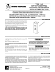
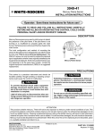
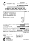
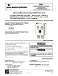
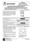
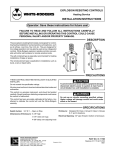
11D06, 11D37, 11D82
REMOTE BULB
HOT WATER CONTROL
WHITE-RODGERS
INSTALLATION INSTRUCTIONS
Operator: Save these instructions for future use!
FAILURE TO READ AND FOLLOW ALL INSTRUCTIONS CAREFULLY BEFORE
INSTALLING OR OPERATING THIS CONTROL COULD CAUSE PERSONAL
INJURY AND/OR PROPERTY DAMAGE.
DESCRIPTION
These controls are designed for use on hot water heating
installations. They have; open on rise, close on rise, or S.P.D.T.
switch action and are available with either fixed or adjustable
differential.
These controls are equipped with remote bulb feature for ease
of installation in hard to reach locations.
PRECAUTIONS
THESE CONTROLS MUST BE INSTALLED BY A QUALIFIED
INSTALLER.
Do not exceed the specification ratings.
All wiring must conform to local and national electrical codes
and ordinances.
CAUTION
To prevent electrical shock and/or equipment damage, disconnect electric power to system, at main fuse
or circuit breaker box, until installation is complete.
This control is a precision instrument, and should be handled
carefully. Rough handling or distorting components could cause
the control to malfunction.
This control has been accurately calibrated at the factory. Any
attempt to calibrate this control will void the White-Rodgers
warranty.
WARNING
Do not use on circuits exceeding specified voltages.
Higher voltages will damage control and could cause
shock or fire hazard.
INSTALLATION
If the boiler manufacturer recommends a control location, follow
such recommendations. If none is offered, the following information gives suggested locations.
When used for high limit service, the control should be installed in the riser close to the boiler, or in a boiler tapping that
is near the top or hottest section of the boiler. If the boiler is also
used to heat domestic hot water, make sure that the high limit
control is not located in the section of the boiler that contains the
heat exchanger or piping for domestic hot water.
When used for low limit or operator service, the control should
be located near that section of the boiler that contains the heat
exchanger or piping for domestic hot water.
WHITE-RODGERS DIVISION
EMERSON ELECTRIC CO.
9797 REAVIS RD., ST. LOUIS, MO. 63123
(314) 577-1300, FAX (314) 577-1517
9999 HWY. 48, MARKHAM, ONT. L3P 3J3
(905) 475-4653, FAX (905) 475-4625
To remove the well from the control, loosen the set screw in the
large nut, then slide the well off to expose the bulb. Screw the
well into the proper tapping. Slide the bulb back into the well,
making sure that the bulb enters the well as far as it will go and
tighten the set screw.
CAUTION
Do not dent or bend the bulb as this will prevent it from
fitting into the well properly.
PART NO. 37-2562B
Printed in U.S.A.
Replaces 37-2562 & 37-9460
9548
WIRING
All wiring should be done in accordance with local and national electrical codes and ordinances.
RED
11D06 .................... OPEN ON RISE
11D37 .................... CLOSE ON RISE
11D82 .................... S.P.D.T.
BLUE
OPEN ON RISE
OF TEMPERATURE
COMMON
WHITE
CLOSE ON RISE
OF TEMPERATURE
SETTING THE CONTROL
CONTROLS WITH ADJUSTABLE DIFFERENTIAL
1. Insert a screwdriver in the centre slot and turn the dial until
the right hand indicator “B” points to the lowest temperature
of the cycle.
2. Turn the differential adjusting screw “C” until the left hand
indicator “D” points to the highest temperature of the cycle.
The left-hand indicator points to the temperature at which the
contacts open on high limit and low limit applications. On
circulator applications, the left-hand indicator points to the
temperature at which the circulator will start.
On combination low limit and circulator applications, the
left-hand indicator points to the temperature at which the low
limit stops the burner and permits the circulator to run.
CONTROLS WITH FIXED DIFFERENTIAL
Insert a screwdriver in centre slot “A” and turn the dial until the
fixed indicator “B” points to the highest desired temperature of
the cycle.
The fixed indicator points to the temperature at which the
contacts open on high limit and low limit applications. On
circulator applications, the fixed indicator points to the temperature at which the circulator will start.
On combination low limit and circulator applications, the
fixed indicator points to the temperature at which the low limit
stops the burner and permits the circulator to run.
“B” FIXED
INDICATOR
“B” FIXED INDICATOR
“A” ADJUSTING
SLOT
“C” DIFFERENTIAL
ADJUSTING SCREW
“A” ADJUSTING
SLOT
“D” MOVABLE INDICATOR
SERVICING
Order wells and heat conductive grease No. 145-0163 separately.
RETAINER CLIP
IMMERSION WELL
Well No.
Description
A
B
C
89-0211
1/2" Std. Shank
1-13/16"
3"
3-5/16"
89-0212
1/2" Std. Ext. Shank
3-5/16"
3"
3-5/16"
89-0213
3/4" Std. Shank
1-13/16"
3"
3-5/16"
89-0214
3/4" Std. Ext. Shank
3-5/16"
3"
3-5/16"
89-0215
3/4" Extra Ext. Shank
4-13/16"
3"
3-5/16"
C
CAPILLARY
RETAINER CLIP
A
2
B
WHITE-RODGERS
11D06, 11D37, 11D82
RÉGULATEUR D’EAU CHAUDE AVEC
CAPTEUR À DISTANCE
INSTRUCTIONS D’INSTALLATION
Utilisateur: conservez ces instructions pour vous y référer au besoin!
SI VOUS NE LISEZ PAS ATTENTIVEMENT CES INSTRUCTIONS AVANT
D’INSTALLER ET D’UTILISER LA COMMANDE, VOUS RISQUEZ DE CAUSER
DES BLESSURES ET DES DOMMAGES MATÉRIELS.
DESCRIPTION
Ce régulateur a été conçu pour servir avec des équipements de
chauffage à eau chaude. Il est doté d’un commutateur à ouverture
sur hausse, à fermeture sur hausse ou unipolaire bidirectionnel.
Le différentiel peut être fixe ou réglable.
La commande est dotée d’un capteur à distance, facilitant son
installation dans les endroits difficiles d’accès.
PRÉCAUTIONS
LA PRÉSENTE COMMANDE DOIT ÊTRE INSTALLÉE PAR
UN TECHNICIEN QUALIFIÉ.
Ne dépassez pas les charges nominales.
Tout le câblage doit être conforme aux codes et règlements
locaux et nationaux qui régissent les installations électriques.
Cette commande est un instrument de précision qui doit être
manipulé avec soin. Elle peut se détraquer si elle est manipulée
de façon négligente ou si des composantes sont déformées.
La commande a été calibrée avec précision lors de la fabrication.
Toute tentative de calibrer l’appareil annulera la garantie de
White-Rodgers.
ATTENTION
Afin de prévenir les chocs électriques et les dommages
matériels pendant l’installation, coupez l’alimentation
électrique au panneau de distribution principal.
AVERTISSEMENT
N’installez pas cet appareil sur des circuits qui dépassent la tension nominale. Une tension trop élevée peut
endommager la commande et poser des risques de
chocs électriques et d’incendie.
INSTALLATION
Si un emplacement de la commande est recommandé par le
fabricant de la chaudière, alors veuillez vous y conformer. Si
aucun emplacement n’est suggéré, veuillez suivre les conseils
suivants.
Si la commande est utilisée comme limiteur à maximum, elle
doit être installée près de la chaudière, sur la colonne montante,
ou dans une ouverture taraudée qui est située dans la partie
supérieure ou dans la section la plus chaude. Si la chaudière
sert aussi pour l’eau chaude domestique, s’assurer que le
limiteur à maximum n’est pas installé dans la partie de la
chaudière où se trouvent l’échangeur de chaleur ou les canalisations d’eau chaude domestique.
Si la commande sert de limiteur à minimum ou d’actionneur,
elle doit alors être installée dans la partie de la chaudière où se
trouvent l’échangeur de chaleur ou les canalisations d’eau
chaude domestique.
WHITE-RODGERS DIVISION
EMERSON ELECTRIC CO.
9797 REAVIS RD., ST. LOUIS, MO. 63123
(314) 577-1300, Télécopieur (314) 577-1517
9999 HWY. 48, MARKHAM, ONT. L3P 3J3
(905) 475-4653, Télécopieur (905) 475-4625
Pour séparer la gaine de la commande, desserrer d’abord la vis
de réglage du gros écrou, puis glisser la gaine pour exposer le
capteur. Visser la gaine dans l’ouverture taraudée qui convient.
Réintroduire ensuite le capteur dans la gaine en prenant soin
qu’il soit bien au fond. Serrer la vis de réglage.
ATTENTION
Ne pas plier ou bosser le capteur, car il serait alors
impossible de l’introduire correctement dans la gaine.
PIÈCE No 37-2562B
Imprimé aux É.-U.A.
Remplace 37-2562 & 37-9460
9548
CÂBLAGE
Tout le câblage doit être conforme aux codes et règlements locaux et nationaux qui régissent les installations électriques.
RED
ROUGE
BLUE
BLEUE
OUVERTURE
Open
on rise
SUR
HAUSSE DE
of
temperature
Common
NEUTRE
11D06 ....................................... OUVERTURE SUR HAUSSE
TEMPÉRATURE
11D37 ....................................... FERMETURE SUR HAUSSE
11D82 ................... UNIPOLAIRE BIDIRECTIONNEL (SPDT)
BLANCHE
WHITE
FERMETURE
CloseSUR
on HAUSSE
rise
DE TEMPÉRATURE
of temperature
RÉGLAGE DE LA COMMANDE
COMMANDES À DIFFÉRENTIEL FIXE
Introduire la pointe d’un tournevis dans la fente de réglage (A).
Tourner le cadran pour que la température maximale souhaitée
du cycle se trouve directement sous l’indicateur fixe (B).
L’indicateur fixe indique la température à laquelle les contacts
seront ouverts lorsque la commande sert de limiteur à maximum
ou de limiteur à minimum. Lorsque la commande sert de
circulateur, l’indicateur fixe indique la température de mise en
marche du circulateur.
Lorsque la commande sert de circulateur avec limiteur à
minimum, l’indicateur fixe indique la température à laquelle le
limiteur à minimum arrêtera le brûleur tout en permettant au
circulateur de fonctionner.
COMMANDES À DIFFÉRENTIEL RÉGLABLE
1. Introduire la pointe d’un tournevis dans la fente de réglage
(A). Tourner le cadran pour que l’indicateur du côté droit (B)
indique la température la plus basse du cycle.
2. Tourner la vis de réglage du différentiel (C) jusqu’à ce que
l’indicateur du côté gauche (D) indique la température la plus
élevée du cycle.
L’indicateur du côté gauche indique la température à laquelle les
contacts seront ouverts lorsque la commande sert de limiteur
à maximum ou de limiteur à minimum. Lorsque la commande
sert de circulateur, l’indicateur du côté gauche indique la
température de mise en marche du circulateur.
Lorsque la commande sert de circulateur avec limiteur à
minimum, l’indicateur du côté gauche indique la température à
laquelle le limiteur à minimum arrêtera le brûleur tout en
permettant au circulateur de fonctionner.
(B) INDICATEUR FIXE
IN
(B) INDICATEUR FIXE
(A) FENTE
DE
TING
RÉGLAGE
(A) FENTE DE
RÉGLAGE
(C) VIS DE RÉGLAGE
DU DIFFÉRENTIEL
(D) INDICATEUR MOBILE
RÉVISION
Commander séparément les gaines et la graisse themoconductrice no 145-0163.
ATTACHE
GAINE D’IMMERSION
No de gaine
Description
A
89-0211
Tige standard 1/2"
1-13/16"
3" 3-5/16"
89-0212
Tige standard allongée 1/2"
3-5/16"
3" 3-5/16"
89-0213
Tige standard 3/4"
1-13/16"
3" 3-5/16"
89-0214
Tige standard allongée 3/4"
3-5/16"
3" 3-5/16"
89-0215
Tige surallongée 3/4"
4-13/16"
3" 3-5/16"
C
TUBE CAPILLAIRE
ATTACHE
A
2
B
B
C