1
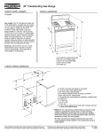
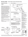
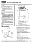
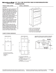
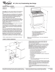
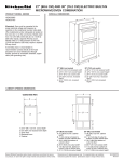
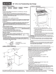
ELECTRICBUILT-INGLASS
SOLIDELEMENTCOOKTOP
1. BEFORE
YOU BEGIN
3. CARPENTRY
Read the following instructions completely and carefully.
followed, they will simplify the installation job.
See Figure 1 for the dimensions of typical counter top cutout. The cut-out must be located so that when the cook top
is set in place there is at least 1% inches between the front
edge of the cook top and the front edge of the counter top.
A 6 inch space must be left between the side(s) of the cook
top and any vertical wall or cabinet extending above the upper
edge of the cook top. This built-in cook top has a shallow
burner box (3”) which allows the unit to be mounted above
the cabinet drawers that are more than 3 inches below the
top of counter top.
If
IMPORTANT:
Observe
all governing
codes and ordinances.
SAVE THESE INSTRUCTIONS
FOR
ELECTRICAL INSPECTOR’S
USE.
THE
LOCAL
2. ELECTRICAL
REQUIREMENTS
4. PREPARATION
INSTALLATION
A three-wire single phase 240 Volt, 60 Hz AC only electrical
supply is required on a separate circuit fused on both sides
of the line (time-delay
fuse or circuit
breaker
is
recommended).
DO NOT fuse neutral. The fuse size must
not exceed the circuit rating of the appliance specified on the
nameplate. NOTE: Wire sizes and connections must conform
with the fuse size and rating of the appliance in accordance
with the National Electrical Code and local codes and
ordinances.
A. Remove the Styrofoam end caps from packaging. Position
them on the counter next to the cutout so they can support
the cooktop.
B. Turn the cooktop upside down and support it on the
endcaps removed in step A. (See figure 2)
FOR
WARNING:
AN EXTENSION CORD SHOULD NOT BE
USED WITH THIS APPLIANCE. SUCH USE MAY RESULT
IN A FIRE, ELECTRICAL SHOCK, OR OTHER PERSONAL
INJURY.
The appliance should be connected to the fused disconnect
(or circuit breaker) box through flexible armored or non-metalic
sheathed cable. The flexible armored cable extending from
the appliance should be connected directly to the junction box.
The junction box should be located as shown in Figure 1 so
that as much slack as possible remains in the cable between
the box and the appliance so that it can be moved if servicing
is ever necessary.
A suitable strain relief must be provided to attach the power
supply cord to the junction box.
FIGURE
2
WARNING:
Reaching
over healed surface
burners
causes risk of being burned.
To reduce risk, installation of cabinet
storage
above surface
units should
be
avoided.
If cabinets
are already
provided,
reduce
hazard by installing
a cooklop
hood. Hood should
extend 5” minimum
beyond
the front of cabmets.
wood or metal cabinet.
24” min. when bottom of wood or
metal cabinet is protected by not less
than YCflame retardant millboard
covered with not less than No. 28 MSG
sheet steel, O.Ol5” stainless steel, 0.024”
aluminum or 0.020” copper.
“‘B”
30”
36”
Dimension
Cooktop
Cooktop
for:
is 26%” min., 295/a” max.
is 33” min.. 34%” max.
Follow
minimum
dimensions
given.
Replacement
installations - be sure that front
edge of cooktop
is at least
l’/r”
back from front edge
I
RECOMMENDED
AREA FOR ELECTRICAL
JUNCTION
BOX (LOCATED
ON REAR WALL
LEAST 9” BELOW COUNTER
TOP.)
FIGURE
2
1
AT
IF CABINET
HAS A DRAWER,
A 3”
DEPTH CLEARANCE
FROM
COUNTERTOPTO
TOPOF
DRAWER
IS REQUIRED.
C. Attach the foam seal strip as follows:
1. Lay foam strip on bottom of cooktop (long side). Cut
strip to fit. (See Figure 2)
2. Remove backing paper from strip.
3. Install strip l/e” in from edge along cooktop side. (See
Figure 2)
4. Repeat steps 1 through 3 for the remaining 3 sides
of cooktop.
Junction
box
\
Cable from
power supply
I I
ires
D. Turn cooktop right side up and again support it on the
end caps next to the cutout.
5. ELECTRICAL
CONNECTION
Bore wire
Connect the flexible armored cable that extends from the
surface unit to the junction box using a suitable strain relief
at the point the armored cable enters the junction box. Then
make the electrical connection as follows:
It is the personal responsibility
to contact a qualified installer
installation is adequate and
National Electrical Code and
and obligation of the customer
to assure that the electrical
is in conformance with the
local code ordinances.
ELECTRICAL
APPLIANCE.
IS
GROUND
REQUIRED
ON
THIS
This appliance is equipped with copper lead wires. If
connection is made to aluminum house wiring, use only
special connectors which are approved for joining copper and
aluminum wires in accordance with the National Electrical
Code and local codes and ordinances.
This appliance is manufactured
grounding wire.
with a frame-connected
bare
Where local codes permit connecting the frame-grounding
conductor to the neutral (white) junction box wire:
Junction
box
\
’
Strain
relief
Eif
Cable
from cooktop
FIGURE
4
1. Connect the two black wires. Then connect the two red
wires. (See figure 4)
2. Connect the green or bare grounding wire from the
appliance cable to a grounded wire in the junction box or to
a grounded, copper, cold water pipe.
3. DO NOT ground to a gas supply pipe. Do Not connect
to electrical supply until appliance is permanently grounded.
(See figure 5) Grounded, cold water pipe must have metal
continuity to electrical ground and not be interrupted by
plastic, rubber or other insulating, electrical connectors such
as hoses, fittings, washers or gaskets (including water meter
or pump). Any insulating, electrical connector should be
jumped as shown with a length of No. 4 copper wire securely
clamped to bare metal at both ends.
Cable from
power supply
. h
I
Red
wire
k
wires
Bare wire
H
‘Strain
relief
m
Cable
from cooktop
FIGURE
3
FIGURE
1. Connect together 2 wires: the green or bare appliance
cable wire and the white wire in the junction box.
2. Connect the two black wires. Then connect the two red
wires. (See figure 3)
Where local codes DO NOT permit connecting the framegrounding conductor to the neutral (white) junction box wire:
5
6. INSTALLATION
A. Center cooktop in the countertop opening. If cooktop is
not properly positioned, lift complete unit and lower it again.
This is to prevent any damage to the foam seal strip.
6. Assemble
the two clamps.
(See figure
6)
GIASSCOOKTOP
FOAM
THUMB
COUNTER
SEAL
TOP
SCREW
BURNER
BOX
FIGURE 6
7. CHECK
BURNER
OPERATION
REFER TO USE AND CARE GUIDE PACKAGED WITH THE
BUILT-IN COOK TOP TO CHECK FOR PROPER CARE AND
CLEANING OF YOUR BUILT-IN COOK TOP.
BOX
CAUTION: Do not touch the elements. They may be hot and
you may get burned.
Turn on each of the four (4) surface elements and check to
see that they heat. Check the surface element indicator lights.
8. SERIAL PLATE LOCATION
The serial plate is located on the bottom of the burner box.
THUMB
UNDERNEATH
COUNTER
BEFORE YOU CALL
FOR SERVICE
SCREW
CLAMP
CHECK TO MAKE SURE THE HOUSE FUSE OR CIRCUIT
BREAKER FOR YOUR BUILT-IN COOK TOP IS NOT
BLOWN OR OPEN.
FIGURE 7
C. Working below the countertop, insert one clamp into slot
located on either side of the burner box. (See figure 7)
My Selling Dealer:
D. Rotate clamps so that thumb screws are vertical.
NAME
To secure cooktop to countertop, hand-tighten each thumb
screw while lightly applying pressure to countertop above
each clamp. (See figure 8)
ADDRESS
CAUTION: Do not overtighten thumb screws.
enough tension to hold the unit in place.
PHONE
Apply only
In the event your WHIRLPOOL
appliance
should need service,
call the dealer from whom you purchased
the
appliance or a WHIRLPOOL franchised TECH-CARE@ service company. He is in the Yellow Pages of your
telephone directory listed under “Appliances-Household-Major-Service and Repair.” You can also obtain his
name and number by dialing, free, the Whirlpool COOL-LINE @ Service (800) 253-1301. Dial just as you
normally dial long distance. A special operator will tell you the name and number of your nearest Whirlpool
TECH-CARE
service
outlet, During normal working
hours, Whirlpool
consultants
at this same number will also
answer any questions about operating or maintaining your appliance not covered in your Use and Care Guide.
Learn the benefits
appliances.
WHIRLPOOL
of using TECH-CARE
CORPORATION,
service
BENTON
4
for maintaining
HARBOR,
the quality originally
MICHIGAN
built into your Whirlpool
49022
Part No. 4211803
Rev. C