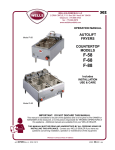
1
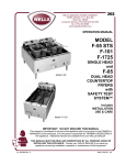
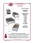
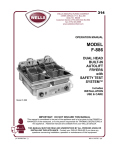
302
WELLS BLOOMFIELD, LLC
2 ERIK CIRCLE, P. O. Box 280 Verdi, NV 89439
telephone: 775-689-5703
fax: 775-689-5976
www.wellsbloomfield.com
OPERATION MANUAL
MODEL
F-55 STS
F-101
F-1725
SINGLE HEAD
and
Model F-85
F-85
DUAL HEAD
COUNTERTOP
FRYERS
with
SAFETY TEST
SYSTEM™
Includes
INSTALLATION
USE & CARE
Model F-1725
IMPORTANT: DO NOT DISCARD THIS MANUAL
This manual is considered to be part of the appliance and is to be given to the OWNER or
MANAGER of the restaurant, or to the person responsible for TRAINING OPERATORS of
this appliance. Additional manuals are available from your WELLS DEALER.
THIS MANUAL MUST BE READ AND UNDERSTOOD BY ALL PERSONS USING OR
INSTALLING THIS APPLIANCE. Contact your WELLS DEALER if you have any
questions concerning installation, operation or maintenance of this equipment.
PRINTED IN UNITED STATES OF AMERICA
p/n 304356 Rev. C
ECN-13378
M302
071029
cps
LIMITED WARRANTY STATEMENT
Unless otherwise specified, all commercial cooking
equipment manufactured by WELLS BLOOMFIELD, LLC is
warranted against defects in materials and workmanship for
a period of one year from the date of original installation or
18 months from the date of shipment from our factory,
whichever comes first, and is for the benefit of the original
purchaser only.
THIS WARRANTY IS THE COMPLETE AND ONLY
WARRANTY, EXPRESSED OR IMPLIED IN LAW OR IN
FACT, INCLUDING BUT NOT LIMITED TO, WARRANTIES
OF MERCHANTABILITY OR FITNESS FOR ANY
PARTICULAR PURPOSE, AND/OR FOR DIRECT,
INDIRECT OR CONSEQUENTIAL DAMAGES IN
CONNECTION WITH WELLS BLOOMFIELD PRODUCTS.
This warranty is void if it is determined that, upon inspection
by an authorized service agency, the equipment has been
modified, misused, misapplied, improperly installed, or
damaged in transit or by fire, flood or act of God. It also
does not apply if the serial nameplate has been removed, or
if service is performed by unauthorized personnel. The
prices charged by Wells Bloomfield for its products are
based upon the limitations in this warranty. Seller’s
obligation under this warranty is limited to the repair of
defects without charge by a Wells Bloomfield factory
authorized service agency or one of its sub-service
agencies. This service will be provided on customer’s
premises for non-portable models. Portable models (a
device with a cord and plug) must be taken or shipped to
the closest authorized service agency, transportation
charges prepaid, for service. In addition to restrictions
contained in this warranty, specific limitations are shown in
the Service Policy and Procedure Guide. Wells Bloomfield
authorized service agencies are located in principal cities.
This warranty is valid in the United States and Canada and
void elsewhere. Please consult your classified telephone
directory, your foodservice equipment dealer or contact:
Service Department, Wells Bloomfield, LLC
P.O. Box 280, Verdi, Nevada 89439
phone (775) 689-5707 or fax (775) 689-5976
for information and other details concerning warranty.
SERVICE POLICY AND PROCEDURE GUIDE and ADDITIONAL WARRANTY EXCLUSIONS
1.
2.
3.
4.
6.
cleaning schedules, are customer responsibility. Those
miscellaneous adjustments noted are customer
responsibility. Proper attention to preventative
maintenance and scheduled maintenance procedures
will prolong the life of the appliance.
7. Travel mileage is limited to sixty (60) miles from an
Authorized Service Agency or one of its sub-service
agencies.
8. All labor shall be performed during regular working
hours. Overtime premium will be charged to the buyer.
9. All genuine Wells replacement parts are warranted for
ninety (90) days from date of purchase on nonwarranty equipment. This parts warranty is limited only
to replacement of the defective part(s). Any use of
non-genuine Wells parts completely voids any
warranty.
10. Installation, labor, and job check-outs are not
considered warranty and are thus not covered by this
warranty.
11. Charges incurred by delays, waiting time or operating
restrictions that hinder the service technician’s ability to
perform service are not covered by warranty. This
includes institutional and correctional facilities.
SHIPPING DAMAGE CLAIM PROCEDURE
NOTE: For your protection, please note that equipment in
this shipment was carefully inspected and packaged by
skilled personnel before leaving the factory. Upon
acceptance of this shipment, the transportation company
assumes full responsibility for its safe delivery.
IF SHIPMENT ARRIVES DAMAGED:
1. VISIBLE LOSS OR DAMAGE: Be certain that any
visible loss or damage is noted on the freight bill or
express receipt, and that the note of loss or damage is
signed by the delivery person.
2. FILE CLAIM FOR DAMAGE IMMEDIATELY:
Regardless of the extent of the damage.
3.
CONCEALED LOSS OR DAMAGE: if damage is
unnoticed until the merchandise is unpacked, notify the
transportation company or carrier immediately, and file
“CONCEALED DAMAGE” claim with them. This
should be done within fifteen (15) days from the date
the delivery was made to you. Be sure to retain the
container for inspection.
Wells Bloomfield cannot assume liability for damage or loss
incurred in transit. We will, however, at your request, supply
you with the necessary documents to support your claim.
xi
302 p/n 304356 OpM CT Fryers STS
5.
Resetting of safety thermostats, circuit breakers, over
load protectors, and/or fuse replacements are not
covered by this warranty unless warranted conditions
are the cause.
All problems due to operation at voltages or phase
other than specified on equipment nameplates are
not covered by this warranty.
Conversion to correct voltage and/or phase must be
the customer’s responsibility.
All problems due to electrical connections not made
in accordance with electrical code requirements
and wiring diagrams supplied with the equipment are
not covered by this warranty.
Replacement of items subject to normal wear, to
include such items as knobs, light bulbs; and, normal
maintenance functions including adjustments of
thermostats, adjustment of micro switches and
replacement of fuses and indicating lights are not
covered by warranty.
Damage to electrical cords and/or plug due to exposure
to excessive heat are not covered by this warranty.
Full use, care, and maintenance instructions supplied
with each machine. Noted maintenance and
preventative maintenance items, such as servicing and
TABLE OF CONTENTS
WARRANTY
SPECIFICATIONS
FEATURES & OPERATING CONTROLS
PRECAUTIONS & GENERAL INFORMATION
AGENCY LISTING INFORMATION
INSTALLATION
OPERATION
CLEANING INSTRUCTIONS
MAINTENANCE
TROUBLESHOOTING SUGGESTIONS
PARTS & SERVICE
CUSTOMER SERVICE DATA
xi
1
2
3
4
4
6
7
8
8
9
9
INTRODUCTION
Thank You for purchasing this Wells Bloomfield appliance.
Proper installation, professional operation and consistent maintenance of this appliance will ensure that
it gives you the very best performance and a long, economical service life.
302 p/n 304356 OpM CT Fryers STS
This manual contains the information needed to properly install this appliance, and to use and care for
the appliance in a manner which will ensure its optimum performance.
SPECIFICATIONS
MODEL
VOLTS
AMPS
WATTS
F-55 STS
208VAC 3ø
L1 = 15.9A / L2 = 15.9A / L3 = 15.9A
5,750W
240VAC 3ø
L1 = 13.8A / L2 = 13.8A / L3 = 13.8A
5,750W
208VAC 3ø
L1 = 31.9A / L2 = 31.9A / L3 = 31.9A
11,500W
240VAC 1ø
47.9A
11,500W
240VAC 3ø
L1 = 27.6A / L2 = 27.6A / L3 = 27.6A
11,500W
480VAC 3ø
L1 = 13.8A / L2 = 13.8A / L3 = 13.8A
11,500W
F-85EU
380-415VAC 3ø
L1 = 16.0A / L2 = 16.0A / L3 = 16.0A
11,100W
F-101
208VAC 3ø
L1 = 33.3A / L2 = 33.3A / L3 = 33.3A
12,000W
240VAS 3ø
L1 = 28.9A / L2 = 28.9A / L3 = 28.9A
12,000W
208VAC 3ø
L1 = 47.8A / L2 = 47.8A / L3 = 47.8A
17,250W
240VAC 3ø
L1 = 41.5A / L2 = 41.5A / L3 = 41.5A
17,250W
F-85
F-1725
1
FEATURES & OPERATING CONTROLS
302 p/n 304356 OpM CT Fryers STS
Fig. 1 Countertop Fryer with Safety Test System™ Features & Operating Controls
F-85 Shown - F-55STS, F-101 and F1725 are Similar
2
PRECAUTIONS AND GENERAL INFORMATION
DANGER: BURN HAZARD
Contact with hot oil will cause severe burns. Always wear protective clothing and heat
resistant gloves when operating the fryer or filtering the oil.
WARNING: ELECTRIC SHOCK HAZARD
All servicing requiring access to non-insulated components must be performed by
qualified service personnel. DO NOT open any access panel that requires the use of
tools. Failure to heed this warning may result in severe electric shock.
CAUTION: BURN HAZARD
Contact with hot oil may cause burns. DO NOT fill fryer beyond MAX OIL line on frypot.
For disposal of oil use only a container specifically designed for the disposal of hot oil.
DO NOT fill hot oil disposal container beyond MAX OIL line.
This appliance is intended for use in commercial establishments
only.
This appliance is intended to prepare food for human consumption.
No other use is recommended or authorized by the manufacturer or its
agents.
Operators of this appliance must be familiar with the appliance use,
limitations and associated restrictions. Operating instructions must be
read and understood by all persons using or installing this appliance.
302 p/n 304356 OpM CT Fryers STS
Cleanliness of this appliance is essential to good sanitation. Read and
follow all included cleaning instructions and schedules to ensure the
safety of the food product.
Disconnect this appliance from electrical power before performing any
maintenance or servicing.
DO NOT submerge this appliance in water. This appliance is not jet
stream approved. Do not direct water jet or steam jet at this appliance,
or at any control panel or wiring. Do not splash or pour water on, in or
over any controls, control panel or wiring.
Exposed surfaces of this appliance can be hot to the touch and may
cause burns.
The technical content of this manual, including any wiring diagrams,
schematics, parts breakdown illustrations and/or adjustment
procedures, is intended for use by qualified technical personnel.
Any procedure which requires the use of tools must be performed by a
qualified technician.
Refer to the General Layout Data packed with the fryer for wire size
requirements, clearances and other important installation data.
This manual is considered to be a permanent part of the appliance.
This manual and all supplied instructions, diagrams, schematics, parts
breakdown illustrations, notices and labels must remain with the
appliance if it is sold or moved to another location.
This appliance is made in the USA. Unless otherwise noted, this
appliance has American sizes on all hardware.
3
CAUTION:
RISK OF
DAMAGE
DO NOT connect or
energize this appliance
until all installation
instructions are read and
followed. Damage to the
appliance will result if
these instructions are not
followed.
CAUTION:
HOT SURFACE
Exposed surfaces can be hot
to the touch and may cause
burns.
AGENCY LISTING INFORMATION
This appliance conforms to NSF Standard 4 for sanitation only if
installed in accordance with the supplied Installation Instructions and
maintained according to the instructions in this manual.
This appliance is U Listed under UL File E6070 for 120V, 208V and
240V.
STD 4
E6070
INSTALLATION
UNPACKING & INSPECTION
Carefully remove the appliance from the carton. Remove all
protective plastic film, packing materials and accessories from the
Appliance before connecting electrical power or otherwise performing
any installation procedure.
Carefully read all instructions in this manual and the Installation
Instruction Sheet packed with the appliance before starting any
installation.
Read and understand all labels and diagrams attached to the
appliance.
Carefully account for all components and accessories before
discarding packing materials. Store all accessories in a convenient
place for later use.
NOTE: DO NOT discard
the carton or other packing
materials until you have
inspected the appliance for
hidden damage and tested it
for proper operation.
Refer to SHIPPING DAMAGE
CLAIM PROCEDURE on the
inside front cover of this
manual.
IMPORTANT:
This installation must comply
with all applicable Federal,
Local and NFPA codes.
302 p/n 304356 OpM CT Fryers STS
COMPONENTS
1 ea. FRYPOT (all except F-85) or 2 ea. FRYPOT (F-85)
2 ea. FRY BASKETS
4 ea. ADJUSTABLE LEGS
SETUP
Setup the appliance only on a firm, level, non-combustible surface.
Verify local codes for requirements. Concrete, tile, terrazzo or metal
surfaces are recommended. Metal over combustible material may not
meet code for non-combustible surfaces.
Install one adjustable leg at each corner of the fryer by screwing the leg
into the fitting on the bottom. With a spirit level, check that the appliance is level front-to-back and side-to-side. Verify that the unit sits
firmly ON ALL FOUR LEGS.
The lower portions of the legs are adjustable by turning; adjust as
required to level the appliance. All four legs must be adjusted to firmly
contact the counter in order to prevent tipping.
Refer to the Installation Instruction Sheet for required clearances.
Maintain required clearances between the appliance and adjacent
combustible surfaces.
Avoid storing flammable or combustible materials in, on or near the
appliance.
Fig. 2 Adjustable Legs
4
INSTALLATION (continued)
WARNING: ELECTRIC SHOCK HAZARD
All servicing requiring access to non-insulated electrical components must be
performed by a factory authorized technician.
DO NOT open any access panel which requires the use of tools. Failure to follow this
warning can result in severe electrical shock.
IMPORTANT: Refer to the General Layout Data packed with the fryer
for wire size requirements and other installation data.
F-55 STS FRYER ELECTRICAL INSTALLATION
F-55 fryers must be connected directly to an appropriately sized electric
circuit. Conduit and strain relief must be provided by the electrician.
F-55 fryers require a 208VAC or 240VAC 20 amp three-phase circuit
with ground.
Raise the element head, remove the frypot and the cover at the inside
rear of the fryer to gain access to the terminal block. The electrical inlet
is provided by a knock-out in the rear panel.
If an equipment shutdown interface is required by local fire code, the
flame sensor terminal block may be accessed by removing the cover at
the inside rear of the fryer Replace the jumper of the terminal block
with wiring to a normally closed contact of the building fire management
system.
DO NOT connect power to the flame sensor terminal block. Wiring and
contacts must be capable of handling 20 amps.
302 p/n 304356 OpM CT Fryers STS
F-85 FRYER ELECTRICAL INSTALLATION
F-85 fryers must be connected directly to an appropriately sized electric
circuit. Conduit and strain relief must be provided by the electrician.
F-85 fryers require either a 240VAC 50 amp single phase circuit with
ground; a 208VAC or 240VAC 40 amp three phase circuit with ground,
or a 480VAC 20 amp three phase circuit with ground. Units are shipped
from the factory wired for three phase. Conversion of 240VAC units to
single phase must be performed in the field by the electrician.
Raise the element head, remove the frypot and the cover at the inside
rear of the fryer to gain access to the terminal block. The electrical inlet
is provided by a knock-out in the rear panel.
F-101 and F-1725 FRYER ELECTRICAL INSTALLATION
F-101 and F-1725 fryers must be connected directly to an appropriately
sized electric circuit. Conduit and strain relief must be provided by the
electrician. F-101 fryers require a 208VAC or 240VAC 40 amp three
phase circuit with ground,
F-1725 fryers require a 208VAC or 240VAC 50 amp three phase circuit
with ground, Units are shipped from the factory wired for three phase.
F-101 and F-1725 fryers are not approved for conversion to single
phase.
Raise the element head, remove the frypot and the cover at the inside
rear of the fryer to gain access to the terminal block. The electrical inlet
is provided by a knock-out in the rear panel.
5
CAUTION:
RISK OF
DAMAGE
DO NOT connect or energize
this appliance until all
installation instructions are
read and followed. Damage
to the appliance will result if
these instructions are not
followed.
CAUTION:
ELECTRIC
SHOCK HAZARD
The ground lug of fryers must
be connected to a suitable
building electric ground.
IMPORTANT:
Damage due to being
connected to the wrong
voltage or phase is NOT
covered by warranty.
OPERATION
DANGER: BURN HAZARD
Contact with hot oil will cause severe burns.
Always wear protective clothing and heat resistant gloves when operating the fryer.
CAUTION:
NORMAL OPERATION
HOT SURFACE
1. a. Be sure the TEMPERATURE CONTROL KNOB is turned to
OFF.
b. Lower the ELEMENT HEAD into the frypot by pushing back on
the BASKET SUPPORT ROD, raising the ELEMENT HEAD
SUPPORT ROD, then carefully lowering the elements.
Exposed surfaces can be hot
to the touch and may cause
burns.
2. Fill the FRYPOT with commercial-grade liquid shortening to the
MIN OIL line.
Capacity: 15 pounds (F-55), OR 30 pounds (F-85, F-101, F-1725.
IMPORTANT: DO NOT overfill the frypot. Cold oil will expand as it
heats. Adding too much oil will allow the frypot to overflow during
operation.
For best results, always use top grade commercial shortening made
specially for frying. Maintain proper oil level in frypot during
operation.
3. Press the POWER SWITCH to the ON position. The indicator in
the switch will glow.
Fig. 3 Temperature Control
Knob
5. Load either or both baskets no more than 1/2 full with food product.
a. DO NOT overload fry baskets. For best results, load baskets
uniformly to half full.
b. Using the basket handle, lower the baskets into the hot oil.
c. When food is cooked, lift the basket out of the oil by the handle.
Hang the baskets on the BASKET SUPPORT ROD to drain.
Fig. 4 Oil Level Marking
NOTE: If the oil temperature
exceeds 440ºF, the hi-limit
safety will shut down the unit,
and light the red TROUBLE
light. To reset:
Allow the oil to cool, then
press the red button on the
back of the element head
until it “clicks” and stays in.
If tripping persists, see
Troubleshooting Suggestions,
page 9.
6. When the heat indicator light cycles off, the fryer is ready to cook
the next load.
7. Reduce temperature control to 225ºF during idle periods to save
power and extend the life of the oil. The fryer will return to
operating temperature in just a few minutes when needed.
8. Keep the fryer clean at all times. Rinse baskets frequently, and dry
thoroughly, in order to prevent oil contamination.
9. Drain the frypot completely after use. Filter the oil daily, or more
often during heavy use.
6
302 p/n 304356 OpM CT Fryers STS
4. Turn the TEMPERATURE CONTROL KNOB to the desired
temperature. The HEAT INDICATOR will glow. When the oil
reaches the desired temperature, the heat indicator will go out. The
heat indicator will go off and on during operation as the thermostat
cycles to maintain temperature.
For best results: DO NOT set temperature control to a temperature
setting higher than is required for the food product.
OPERATION—SAFETY TEST SYSTEM™
DANGER: BURN HAZARD
Contact with hot oil will cause severe burns. Allow the fryer to cool before cleaning.
Always wear protective clothing and heat resistant gloves when performing this test.
1. Fill the frypot to the MIN OIL line. Fresh oil is recommended to
minimize smoking.
2. Clip the TEST THERMOMETER to a
FRYER BASKET. Lower the fryer
basket into the oil. Be sure the dial
of the test thermometer can be
clearly viewed.
The hi-limit thermostat is
factory set for 440ºF (227ºC).
It will trip if the oil temperature
exceeds this setting, and
interrupt power to the heating
element.
3. Turn the TEMPERATURE
CONTROL KNOB to the maximum
setting, then press the POWER
SWITCH to ON. Allow the oil to heat
until the test thermometer reads to
“START TEST” (350ºF).
CAUTION
FIRE HAZARD
4. Press and hold the red TEST
Fig. 5 Test Thermometer
SWITCH. The temperature of the
oil will rise, and the test thermometer
will read “TEST ZONE”.
IMPORTANT: DO NOT hold the TEST switch for more than
2-1/2 minutes.
302 p/n 304356 OpM CT Fryers STS
When the oil temperature reaches the setting of the hi-limit
thermostat, the hi-limit will trip, the red TROUBLE light will glow,
and the heating element will be de-energized.
If the hi-limit thermostat trips while the test
thermometer is in the TEST ZONE, the test is
complete. The function of the hi-limit
thermostat is normal. Reset the hi-limit
thermostat and resume normal operation.
FAIL!
The Safety Test System™
allows a positive test of the
function of the temperature
limiting (hi-limit) thermostat.
If the test thermometer rises above the TEST
ZONE, the hi-limit is not operating properly.
Release the TEST switch, turn the power
switch OFF and contact an Authorized Wells
Service Agent for repairs.
5. Reset the hi-limit thermostat:
a. Turn the power switch OFF
b. Allow the oil to cool
c. Press the red button on the back of the element head until it
“clicks” and stays in.
6. Remove, clean and store the test thermometer.
Set the temperature control knob to the normal operating
temperature. Turn the power switch ON and resume normal
operation.
7
Do not hold the TEST switch
for more than 2-1/2 minutes.
Should the oil temperature not
reach the hi-limit setting within
2-1/2 minutes, turn the power
switch OFF and contact an
Authorized Wells Service
Agent for repairs.
CLEANING INSTRUCTIONS
DANGER: BURN HAZARD
Contact with hot oil will cause severe burns. Allow the fryer to cool before cleaning.
Always wear protective clothing and heat resistant gloves when cleaning the fryer.
CAUTION:
PREPARATION
Turn temperature control to OFF
Allow fryer to cool completely before cleaning
Unplug fryer from receptacle before cleaning
FREQUENCY
Daily, or as needed
TOOLS
Mild Detergent, Non-abrasive cleanser
Soft Cloth or Sponge, Plastic Scouring Pad
Container for disposal of used oil.
ELECTRIC
SHOCK HAZARD
Disconnect fryer from electric
power before cleaning.
CAUTION:
BURN HAZARD
Allow fryer to cool completely
before cleaning.
CLEANING
1. Turn temperature control to OFF. Unplug the fryer.
CAUTION:
ELECTRIC
SHOCK HAZARD
Do not submerge fryer in
water.
IMPORTANT: DO NOT spill
or pour water into controls,
control panel or wiring.
IMPORTANT: DO NOT use
steel wool or abrasive
cleansers for cleaning the
fryer cabinet or frypot.
To remove carbonization from
frypot and element, see
PERIODIC CLEANING on
page 10.
IMPORTANT:
Nickel plated frypot must be
dried completely in order to
prevent rusting, and to
eliminate water contamination
of the cooking oil.
3. Allow the oil to cool to a safe temperature (120ºF or less).
Carefully remove the frypot: wearing heat-resistant gloves, lift the
frypot by the handles. Drain the oil into a suitable container.
4. Frypot and baskets may be washed in a dishwasher, or with warm
water and mild detergent. Rinse thoroughly and dry completely.
5. Wipe/brush all crumbs, breading and cooking debris from
elements. Pay particular attention to the area between the element
and the thermobulbs. Be careful that the capillary tubes of the
thermobulbs are not moved or damaged during cleaning.
6. Keep all exterior surfaces free from splashed grease by wiping with
a clean cloth dampened with warm water and mild detergent. A
non-abrasive detergent and plastic scouring pad may be used for
stubborn deposits.
IMPORTANT: DO NOT use steel wool or abrasive cleansers
as these will damage the surface finish.
IMPORTANT: DO NOT submerge fryer in water. DO NOT spill or
pour water into controls, control panel or wiring. Damage to
internal components will occur.
7. Be certain frypot is completely dry, then reinstall in fryer.
a. Be sure the TEMPERATURE CONTROL KNOB is turned to
OFF, then plug unit into receptacle.
b. Lower the ELEMENT HEAD into the frypot by pushing back on
the ELEMENT LIFTING HANDLE, raising the SUPPORT ROD,
then carefully lowering the elements.
c. Add new or filtered oil to the MIN OIL line in frypot
Procedure is complete.
8
302 p/n 304356 OpM CT Fryers STS
DO NOT submerge fryer in
water. Damage to internal
components will occur.
Damage to internal
components from water
damage is not covered by
warranty.
2. Remove fry baskets, then swing the element head up and out of
the frypot.
NOTE: The element support rod is spring-loaded. When the
element head is raised, the support rod will automatically swing
into position to keep the element head raised.
DISPOSAL OF USED OIL
DANGER: BURN HAZARD
Contact with hot oil will cause severe burns. Allow the fryer to cool before cleaning.
Always wear protective clothing and heat resistant gloves when handling hot oil.
PREPARATION Turn temperature control to OFF
Allow fryer to cool completely before draining
FREQUENCY
Daily, or as needed
TOOLS
Container for disposal of used oil.
CAUTION:
BURN HAZARD
Allow fryer to cool completely
before draining.
OIL DISPOSAL
CAUTION:
1. Turn temperature control to OFF.
SLIP AND FALL
HAZARD
2. Allow the oil to cool to a safe temperature (120ºF or 50ºC).
3. Raise the element head and lift the frypot out of the fryer by the
frypot handles.
4. Dispose of the used oil in an approved oil disposal receptacle, or
filter the oil for reuse.
5. Wipe the frypot and reinstall in the fryer.
Clean up oil spills
immediately. Slipping in oil
can cause injury.
CAUTION:
HEALTH
HAZARD
Clean up oil spills
immediately. Oil provides an
environment for the growth of
bacteria, which presents a
health hazard.
302 p/n 304356 OpM CT Fryers STS
Procedure is complete.
9
TROUBLESHOOTING SUGGESTIONS
DESCRIPTION
Fryer will not heat
POSSIBLE PROBLEM
SUGGESTED REMEDY
Not plugged in or circuit breaker
tripped
Plug into proper receptacle
Reset circuit breaker
Temperature control knob not set to
desired temperature
Set to desired temperature
Hi-limit safety tripped
Clean element1, reset hi-limit
Damaged internal component
Contact Wells Authorized Service
Agency for repairs
Temperature control thermostat
thermobulb contaminated with
cooking debris
Clean element2
Damaged internal component
Contact Wells Authorized Service
Agency for repairs
Fryer leaks oil
Damaged frypot
Contact Wells Authorized Service
Agency for repairs
Element head will not
raise, will not stay in the
Frypot out of position, or has excess
cooking debris in bottom
Check frypot for position
Clean frypot
up position, or will not
lower
Damaged hinge bracket or support
rod
Contact Wells Authorized Service
Agency for repairs
Fryer will not maintain
temperature
The hi-limit safety is designed to shut down the fryer if the oil temperature exceeds 440ºF. A build-up
of cooking debris between the heating element and the thermobulb of the hi-limit safety will cause the
hi-limit to trip prematurely. Clean the element so that oil may circulate freely between the element
and the thermobulb. Reset the safety by pressing the red button on the bask of the element head.
2
A build-up of cooking debris between the heating element and the thermobulb temperature control
thermostat will cause inconsistent temperatures. Clean the element so that oil may circulate freely
between the element and the thermobulb.
MAINTENANCE
Frypot may be cleaned by
the method described at
right, or with a commercial
frypot cleaner. Be sure to
follow the manufacturer's
directions.
Before cleaning, ALWAYS:
• Unplug the fryer and
allow to cool.
• Drain the oil and wipe
out the frypot.
IMPORTANT:
Nickel plated frypot must be
dried completely in order to
prevent rusting, and to
eliminate water contamination of the cooking oil.
PERIODIC CLEANING
Periodic cleaning is necessary to remove carbonization from the elements
and frypot.
Add 1/2 cup of granulated dishwasher detergent to frypot. Fill with water
to the MAX OIL line.
Lower the element into the frypot and set the control knob to 225ºF
Boil the mixture for five minutes. Turn the control knob to OFF. Allow the
mixture to set in the frypot overnight.
After the soak period, raise the elements and remove any remaining carbonization with a stiff bristle brush. Be careful that the capillary tubes of
the thermobulbs are not moved or damaged during cleaning.
Drain the frypot and wash with warm water and mild detergent.
Reinstall the frypot in the fryer. Add 1 quart of vinegar, then fill to the MAX
OIL line with cold water.
Lower the elements into the vinegar solution. Allow to set for 15 minutes.
Drain the frypot and rinse with clean water. Dry the frypot and elements
thoroughly before returning the fryer to operation.
10
302 p/n 304356 OpM CT Fryers STS
1
PARTS & SERVICE
DESCRIPTION
PART NO.
FRY BASKET, HALF-SIZE FOR F-55, F-85
FRY BASKET, FULL SIZE FOR F-55, F-85
FRYPOT, FOR F-101
FRYPOT, FOR F-55, F-85
FRY BASKET, HALF-SIZE FOR F-101
FRYPOT, FOR F-1725
THERMOMETER, TEST
FRY BASKET, HALF-SIZE FOR F-1725
COVER, FRYPOT FOR F-101, F-1725
COVER, FRYPOT FOR F-55, F-85
LEGS, ADJUSTABLE (Set of 4)
CRUMB CRADLE, FOR F-55, F-85
20161
20162
20167
20169
20287
20519
20537
20820
21009
21010
20563
20690
IMPORTANT: Use only
factory authorized service
parts and replacement
filters.
For factory authorized
service, or to order factory
authorized replacement parts,
contact your Wells authorized
service agency, or call:
Wells Bloomfield, LLC
2 Erik Circle
P. O. Box 280
Verdi, NV 89439
Service Parts Dept.
phone: (775) 689-5707
fax:
(775) 689-5976
302 p/n 304356 OpM CT Fryers STS
Service Parts Department can
supply you with the name and
telephone number of the
WELLS AUTHORIZED
SERVICE AGENCY
nearest you.
CUSTOMER SERVICE DATA
please have this information available if calling for service
RESTAURANT _____________________________ LOCATION _____________
INSTALLATION DATE ________________________ TECHNICIAN ___________
SERVICE COMPANY ________________________________________________
ADDRESS ___________________________ STATE ______ ZIP__________
TELEPHONE NUMBER (_____)_____-_________
EQUIPMENT MODEL NO. _______________
EQUIPMENT SERIAL NO. _______________
VOLTAGE:
208
240
11
1Ø
3Ø
Commercial Food Equipment Service Association
Wells Bloomfield proudly supports CFESA
Commercial Food Equipment Service Association
SERVICE TRAINING - QUALITY SERVICE
Genuine Parts
Protect - YOU - All - Ways
CUSTOMER SATISFACTION
WELLS BLOOMFIELD, LLC
2 ERIK CIRCLE, P. O. Box 280 Verdi, NV 89439
telephone: 775-689-5703
fax: 775-689-5976
www.wellsbloomfield.com
PRINTED IN UNITED STATES OF AMERICA