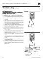
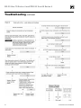
1
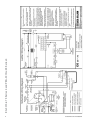
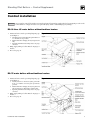
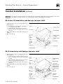
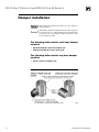
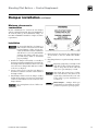
EG-30 thru -75
PEG-30 thru -65
Gas-Fired Boilers – Series 4
Control supplement – Standing pilot
For additional information, refer to . . .
EG•PEG•EGH Boiler manual
for Natural or Propane gas
(tankless heater application optional)
This supplement must only be used by a qualified heating installer/service technician. Before installing, read all
instructions, including this supplement, the boiler manual and any related documents. Perform steps in the order given.
Failure to comply could result in severe personal injury, death or substantial property damage.
Part Number 550-110-032/0607
EG-30 thru 75 Series 4 and PEG-30 thru 65 Series 4
Please read this page first!
Hazard definitions
The following defined terms are used throughout these instructions to bring attention to the
presence of hazards of various risk levels or to important information concerning the life of
the product.
Indicates presence of hazards that will cause severe personal injury, death or
substantial property damage.
Indicates presence of hazards that can cause severe personal injury, death or
substantial property damage.
Indicates presence of hazards that will or can cause minor personal injury or
property damage.
Indicates special instructions on installation, operation or maintenance that are
important but not related to personal injury or property damage.
Note to the installer
Controls must only be installed by a Weil-McLain distributor or other qualified
installer/service technician in accordance with this Supplement and all applicable
codes and requirements of the authority having jurisdiction. Read this Control
Supplement completely before beginning the installation. If the information
in this Supplement is not followed exactly, a fire, explosion, carbon monoxide
emission or other hazardous conditions can result, causing severe personal injury,
death or substantial property damage.
This system is used on gas-fired boilers without vent dampers as shipped from
the factory. This system is not offered for retrofit. Any attempt to apply the system
components to boilers shipped for use with a different control system will not
be covered under boiler warranty and can cause severe personal injury, death or
substantial property damage.
When calling or writing about the boiler, please have the boiler model number
from the boiler rating label and the CP number from the boiler jacket.
Part Number 550-110-032/0607
Standing Pilot Boilers — Control Supplement
Table of contents
Hazard definitions and Note to the installer.....................................................................................2
Control installation — EG-30 thru -75 water boilers without tankless heaters......................... 4-5
Control installation — EG-30 thru -65 water boilers with tankless heaters............................... 6-7
Control installation — EG-30 thru -75 and PEG-30 thru -65 steam boilers with probe............ 8-9
Control installation — EG-30 thru -75 steam boilers with float-type low water cutoff......... 10-11
Damper installation..................................................................................................................... 12-13
Checkout procedure.........................................................................................................................14
Lighting instructions................................................................................................................... 15-18
Troubleshooting........................................................................................................................... 19-23
Replacement parts............................................................................................................................24
Part Number 550-110-032/0607
Part Number 550-110-032/0607
EG-30 thru 75 Series 4 and PEG-30 thru 65 Series 4
Standing Pilot Boilers — Control Supplement
Control installation
For your safety, turn off electrical power supply and turn off external gas supply valve before attempting to work on the
boiler. Failure to comply can cause severe personal injury, death or substantial property damage.
EG-30 thru -65 water boilers without tankless heaters
1. Mount and wire controls per wiring diagram, page
4, and Figure 1.
Figure 1
a. Attach junction box inside left jacket panel with #8-32 x ½” machine screws provided.
b. Install transformer with plug-in relay receptacle and
relay.
c. Operating and limit circuit wiring must be 18 gauge
or heavier.
2. Bring supply wiring to boiler. Must be 14 gauge or
heavier.
3. Proceed to page 12.
EG-75 water boilers without tankless heaters
1. Mount and wire controls per wiring diagram, page
4, and Figure 2.
Figure 2
a. Attach junction box inside left jacket panel with
#8-32 x ½” machine screws and green ground nuts
provided.
b. Install transformer with plug-in relay receptacle and
relay. In Canada, use chain and hook strain relief.
c. Operating and limit circuit wiring must be 18 gauge
or heavier.
2. Bring supply wiring to boiler. Must be 14 gauge or
heavier.
3. Proceed to page 12.
Part Number 550-110-032/0607
Part Number 550-110-032/0607
EG-30 thru 75 Series 4 and PEG-30 thru 65 Series 4
Standing Pilot Boilers — Control Supplement
Control installation
continued
For your safety, turn off electrical power supply and turn off external gas supply valve before attempting to work on the
boiler. Failure to comply can cause severe personal injury, death or substantial property damage.
EG-30 thru -65 water boilers with tankless heaters
1. Mount and wire controls per wiring diagram, page
6, and Figure 3.
Figure 3
a. Install combination limit control and relay in tapping. See Boiler Manual control tapping table. Operating and limit circuit wiring must be 14 gauge or
heavier.
2. Bring supply wiring to boiler. Must be 14 gauge or
heavier.
3. Proceed to page 12.
Note: Tankless heater not available on EG-75 standing pilot boilers.
Part Number 550-110-032/0607
Part Number 550-110-032/0607
EG-30 thru 75 Series 4 and PEG-30 thru 65 Series 4
Standing Pilot Boilers — Control Supplement
Control installation
continued
For your safety, turn off electrical power supply and turn off external gas supply valve before attempting to work on the
boiler. Failure to comply can cause severe personal injury, death or substantial property damage.
EG-30 thru -65 and PEG-30 thru -65 steam boilers with probe-type low water cutoff
1. Mount and wire controls per wiring diagram, page
8, and Figure 4.
Figure 4
a. Attach junction box inside left jacket panel with #8-32 x ½” machine screws provided.
b. Install transformer with plug-in relay receptacle.
c. Operating and limit circuit wiring must be 18 gauge
or heavier.
2. Bring supply wiring to boiler. Must be 14 gauge or
heavier.
3. Proceed to page 12.
EG-75 steam boilers with probe-type low water cutoff
1. Mount and wire controls per wiring diagram, page
8, and Figure 5.
Figure 5
a. Attach junction box inside left jacket panel with
#8-32 x ½” machine screws and green ground nuts
provided.
b. Install transformer with plug-in relay receptacle. In
Canada, use chain and hook strain relief.
c. Operating and limit circuit wiring must be 18 gauge
or heavier.
2. Bring supply wiring to boiler. Must be 14 gauge or
heavier.
3. Proceed to page 12.
Part Number 550-110-032/0607
10
Part Number 550-110-032/0607
EG-30 thru 75 Series 4 and PEG-30 thru 65 Series 4
Standing Pilot Boilers — Control Supplement
Control installation
continued
For your safety, turn off electrical power supply and turn off external gas supply valve before attempting to work on the
boiler. Failure to comply can cause severe personal injury, death or substantial property damage.
EG-30 thru -65 steam boilers with float-type low water cutoff
1. Mount and wire controls per wiring diagram, page
10, and Figure 6.
Figure 6
a. Attach junction box inside left jacket panel with #8-32 x ½” machine screws provided.
b. Install transformer with plug-in relay receptacle.
c. Operating and limit circuit wiring must be 18 gauge
or heavier.
2. Bring supply wiring to boiler. Must be 14 gauge or
heavier.
3. Proceed to page 12.
EG-75 steam boilers with float-type low water cutoff
1. Mount and wire controls per wiring diagram, page
10, and Figure 7.
Figure 7
a. Attach junction box inside left jacket panel with
#8-32 x ½” machine screws and green ground nuts
provided.
b. Install transformer with plug-in relay receptacle. In
Canada, use chain and hook strain relief.
c. Operating and limit circuit wiring must be 18 gauge
or heavier.
2. Bring supply wiring to boiler. Must be 14 gauge or
heavier.
3. Proceed to page 12.
Part Number 550-110-032/0607
11
EG-30 thru 75 Series 4 and PEG-30 thru 65 Series 4
Damper installation
Once damper is installed, boiler will not operate without a
damper installed.
Only dampers listed in the Replacement parts table on page 24 are approved for use on EG and PEG Series 4 standing pilot
boilers. Any other vent damper installed could cause severe
personal injury or death.
The following boiler models must have damper
installed:
• EG-30 thru EG-65, natural or propane gas.
•
PEG-30 thru PEG-65, steam, natural gas.
The following boiler models may have damper
installed:
• EG-75, natural or propane gas.
Figure 8 Vent damper assemblies
12
Part Number 550-110-032/0607
Standing Pilot Boilers — Control Supplement
Damper installation
continued
Minimum clearances to
combustibles
Provide a minimum of 6” between the vent damper
and any combustible material. (Provide a minimum of
46” between jacket top and combustible ceiling.) See
EG • PEG • EGH Boiler manual for complete clearance
requirements.
Installation
Do not modify draft hood or damper, or
make another connection between draft
hood and damper or boiler except as noted below. This will void CSA certification
and will not be covered by Weil-McLain
warranty. Any changes will cause severe
personal injury, death, or substantial
property damage.
1. Install vent damper horizontally or vertically as
shown in vent damper manufacturer’s instructions.
Vent damper must be installed so that it serves only
one boiler and so damper blade indicator is visible
to the user. See Figure 8.
2. Screws or rivets used to secure the vent damper to
the draft hood must not interfere with rotation of
the damper blade.
3. Install damper harness between damper actuator
and knockout in jacket top panel. Use strain relief
connectors and locknuts to secure both ends of the
damper harness.
Keep wiring harness clear of all hot surfaces.
Part Number 550-110-032/0607
4. Read and apply the harness plug warning label
(shown above) so that it is visible after installation.
5. Plug damper harness receptacle into damper harness
plug.
Bypassing (jumpering) vent damper will
cause flue products such as carbon monoxide to escape into the house. This will
cause severe personal injury or death.
After boiler has operated once, if either
end of the harness is disconnected, the
system safety shutdown will occur. The
boiler will not operate until harness is
reconnected.
Effikal damper — Damper hold open
switch must be in “Automatic Operation”
position for system to operate properly.
13
EG-30 thru 75 Series 4 and PEG-30 thru 65 Series 4
Checkout procedure
1. See pages 15-18 for “Lighting Instructions”.
2. Raise room thermostat to call for heat. Damper actuator will slowly open damper.
3. When damper is fully open, main gas valve will open and main burners will ignite.
Damper must be fully open before main burners light. If damper does not fully
open, flue products will escape into house, causing severe personal injury or
death.
4. Lower thermostat setting. Main burner flames will go out, then damper will close.
5. Repeat steps 1 through 3 several times to verify operation.
6. Return thermostat to normal setting.
Room thermostat anticipator settings
Water without tankless heater — 0.40 amps
Water with tankless heater — 0.20 amps
Steam — Select based on gas valve and damper. See table below.
14
Part Number 550-110-032/0607
Standing Pilot Boilers — Control Supplement
Lighting instructions — Robertshaw 7200
Part Number 550-110-032/0607
15
EG-30 thru 75 Series 4 and PEG-30 thru 65 Series 4
Lighting instructions —Honeywell VR8200/VR8300
Natural gas boilers only
16
Part Number 550-110-032/0607
Standing Pilot Boilers — Control Supplement
Lighting instructions —Honeywell VR8200/VR8300
Propane boilers only
Part Number 550-110-032/0607
17
EG-30 thru 75 Series 4 and PEG-30 thru 65 Series 4
Lighting instructions — Robertshaw 7000ERHC
18
Part Number 550-110-032/0607
Standing Pilot Boilers — Control Supplement
Troubleshooting
Burner access panel must be in position during boiler operation to prevent
momentary flame rollout on ignition of
main flame. Severe personal injury or
substantial property damage will result.
Never jumper (bypass) any device except for momentary testing as outlined
in Troubleshooting Charts. Substantial
property damage and/or severe personal
injury could occur.
Label all wires prior to disconnection
when servicing controls. Wiring errors
can cause improper and dangerous operation.
Verify proper operation after servicing. See
vent damper manufacturer’s instructions
packed with vent damper for additional
information. Failure to comply could
result in severe personal injury, death or
substantial property damage.
Before troubleshooting
1. Have a voltmeter that can check 120 VAC, 24 VAC,
and a continuity tester.
2. Check for 120 VAC (minimum 102 to maximum
132) to boiler.
3. Be sure pilot is lit. See “Lighting instructions” on
pages 15-18 for details.
4. Make sure thermostat is calling for heat and contacts
(including appropriate zone controls) are closed.
Check for 24VAC between thermostat wire nuts and
ground.
In event of vent damper failure:
Effikal vent damper
If troubleshooting chart recommends replacing actuator and actuator is
not immediately available, damper blade can be fixed in an open position
to allow boiler operation. Manually turning blade can cause actuator
damage. Follow these instructions only in case of no heat or damper
actuator malfunction.
1. Move damper service switch to Hold Damper Open position. Apply call
for heat to boiler. Damper blade should then rotate to open position
and boiler will fire.
2. If step 1 does not open damper, manually rotate damper blade to open
position using wrench or pliers on flat shaft between damper and actuator. Boiler will fire. Verify that damper service switch is in Hold Damper
Open position (Figure 9).
3. Do not leave vent damper permanently in this position. Replace actuator immediately. If vent damper is left in open position, boiler will not
operate at published efficiencies.
Johnson Controls vent damper
If troubleshooting chart recommends replacing actuator and actuator is
not immediately available, damper blade can be fixed in an open position
to allow boiler operation. Follow these instructions only in case of no heat
or damper actuator malfunction. See Figure 9.
1. Turn off power to boiler.
2.
3.
4.
5.
Failure to turn off power to boiler can result in severe personal
injury, death or substantial property damage.
Refer to vent damper manufacturer’s instructions for procedure to fix
vent damper in open position.
Turn on power to boiler.
Using wrench or pliers on flat shaft section, manually rotate damper
blade until green light turns on. Boiler will fire (Figure 9).
Do not leave vent damper permanently in this position. Replace actuator immediately. If vent damper is left in open position, boiler will not
operate at published efficiencies.
Figure 9 Manually opening vent damper
Part Number 550-110-032/0607
19
EG-30 thru 75 Series 4 and PEG-30 thru 65 Series 4
Troubleshooting
continued
Pilot does not stay lit —
Troubleshooting thermocouple or thermopile
and high limit control circuit
Figure 10
1. Checking thermocouple or thermopile open system (Figure 10):
a. Use an electronic multimeter, with leads fitted with alligator clips. Set meter
scale to DC Millivolts.
b. Unscrew thermocouple or thermopile fitting from gas valve.
c. Attach one meter lead to the end of the thermocouple or thermopile gas
valve fitting.
d. Attach other meter lead to thermocouple or thermopile lead (copper surface).
e. Follow Lighting Instruction label on boiler (also found in Control Supplement or User’s Information Manual) to light the pilot burner only, and hold
the pilot flame manually. (DO NOT light main burner.)
f. Check the reading on the multimeter. The reading should be around 28
millivolts for a thermocouple, or 700 millivolts for a thermopile.
g. If multimeter reading is significantly less than above and pilot flame is
appropriate, replace the thermocouple or thermopile.
2. Checking thermopile and high limit control circuit closed system (Figure 11):
a. Use an electronic multimeter, with leads fitted with alligator clips. Set meter
scale to DC Millivolts.
b. Loosen the insulated terminal on the TOP thermopile lead wire enough to
allow clipping a multimeter alligator clip to the spade terminal.
c. Attach the other multimeter lead to the thermopile lead (copper surface).
Light the pilot burner per step 1 e, above.
d. Check the reading on the multimeter. The reading should be around 400
millivolts.
e. If reading is significantly less than 400 millivolts, check tightness of lead
wire assembly in gas valve. If the connections are secure and you have
checked the thermopile per step 1 above, replace the thermopile lead wire
assembly.
f. If reading on TOP thermopile lead wire is around 400 millivolts, move the
multimeter alligator clip to the BOTTOM thermopile lead wire terminal
and check multimeter reading.
g. If multimeter does not read around 400 millivolts, check wiring connections
and wire integrity to the high limit control.
h. Check voltage at each limit terminal to make sure limit is closed. Correct
pressure or temperature condition causing any limit to be open. Replace
limit if necessary.
20
Figure 11
Part Number 550-110-032/0607
Standing Pilot Boilers — Control Supplement
Troubleshooting
Part Number 550-110-032/0607
continued
21
EG-30 thru 75 Series 4 and PEG-30 thru 65 Series 4
Troubleshooting
22
continued
Part Number 550-110-032/0607
Standing Pilot Boilers — Control Supplement
Troubleshooting
Part Number 550-110-032/0607
continued
23
EG-30 thru 75 Series 4 and PEG-30 thru 65 Series 4
Replacement parts
Only dampers listed below are approved for use on EG-30 thru 75 Series 4, and PEG-30 thru 55 Series 4, standing pilot
ignition system boilers. Any other damper installed can cause severe personal injury or death.
Description
Manufacturer /
Mfr’s part number
Weil-McLain
part number
5” — EG-30 and EG-35; PEG-30 and PEG-35
Effikal RVGP-KS-5BKF
Johnson Q35GD-2
381-800-475
6” — EG-40 and EG-45; PEG-40 and PEG-45
Effikal RVGP-KS-6BKF
Field Controls 02722701
Johnson Q35GF-2
381-800-476
7” — EG-50 and EG-55; PEG-50 and PEG-55
Effikal RVGP-KS-7BKF
Field Controls 02723101
Johnson Q35GH-2
381-800-477
Effikal RVGP-KS-8BKF
Johnson Q35GK-2
381-800-478
Damper actuator
Effikal RVGP
Johnson M35BE-1C
510-512-337
510-312-255
Damper harness
Weil-McLain
591-391-795
Boiler
wiring
harness
EG-30 thru 75 water
EG-35 thru 65 water with tankless
EG-30 thru 75, steam, float LWCO
EG-30 thru 75, PEG-30 thru 65, steam, probe LWCO
Weil-McLain
591-391-864
591-391-865
591-391-866
591-391-867
Pilot kit
EG/PEG-30 thru 65
Natural gas
Propane gas
Weil-McLain
510-811-640
510-811-642
Honeywell Q327A1642
511-330-186
Robertshaw CP-2
511-724-259
Second pressuretrol wire harness
Weil-McLain
591-391-825
Thermopile lead wire, 5”, EG-75
Robertshaw
590-850-561
Honeywell VR8200A2116
Robertshaw 7200ER 7A0-A1B-042
511-044-360
Honeywell VR8300C4050
511-044-256
Robertshaw 7000ERHC-S7C
511-044-505
½” x ½”, Propane gas, sizes 30 thru 50
Honeywell VR8200C1074
511-044-258
¾” x ¾”, Propane gas, sizes 55 thru 65
Honeywell VR8300C4100
511-044-257
Robertshaw 7000ERHC-S7C
511-044-506
Damper
assembly
8” — EG-65 and EG-75; PEG-65
Pilot burner, EG-75
Thermopile, 36” long, EG-75
Gas valve,
natural
gas
½” x ½”, sizes 30 thru 50
¾” x ¾”, 1.2 step, sizes 55 thru 65
¾” x 1”, size 75
Gas valve,
propane
gas
¾” x 1”, Propane gas, size 75
24
Part Number 550-110-032/0607