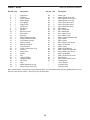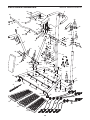
1
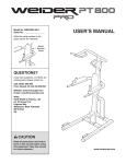
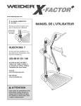
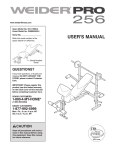
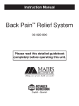
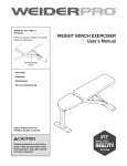
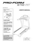
www.weiderfitness.com
Model No. WEBE2910.0
Serial No.
Write the serial number in the
space above for reference.
Serial
Number
Decal
QUESTIONS?
If you have questions, or if parts are
damaged or missing, DO NOT
CONTACT THE STORE; please
contact Customer Care.
IMPORTANT: Please register this
product (see the limited warranty
on the back cover of this manual)
before contacting Customer Care.
1-877-992-5999
CALL TOLL-FREE:
Mon.–Fri., 6 a.m.–6 p.m. MT
Sat. 8 a.m.–4 p.m. MT
ON THE WEB:
www.weiderservice.com
CAUTION
Read all precautions and instructions in this manual before using
this equipment. Keep this manual
for future reference.
USERʼS MANUAL
TABLE OF CONTENTS
WARNING DECAL PLACEMENT . . . . . . . . . . . . . . . . . . . . . . . . . . . . . . . . . . . . . . . . . . . . . . . . . . . . . . . . . . . . . .2
IMPORTANT PRECAUTIONS . . . . . . . . . . . . . . . . . . . . . . . . . . . . . . . . . . . . . . . . . . . . . . . . . . . . . . . . . . . . . . . .3
BEFORE YOU BEGIN . . . . . . . . . . . . . . . . . . . . . . . . . . . . . . . . . . . . . . . . . . . . . . . . . . . . . . . . . . . . . . . . . . . . . .4
PART IDENTIFICATION CHART . . . . . . . . . . . . . . . . . . . . . . . . . . . . . . . . . . . . . . . . . . . . . . . . . . . . . . . . . . . . . .5
ASSEMBLY . . . . . . . . . . . . . . . . . . . . . . . . . . . . . . . . . . . . . . . . . . . . . . . . . . . . . . . . . . . . . . . . . . . . . . . . . . . . . . .6
ADJUSTMENT . . . . . . . . . . . . . . . . . . . . . . . . . . . . . . . . . . . . . . . . . . . . . . . . . . . . . . . . . . . . . . . . . . . . . . . . . . .13
EXERCISE GUIDELINES . . . . . . . . . . . . . . . . . . . . . . . . . . . . . . . . . . . . . . . . . . . . . . . . . . . . . . . . . . . . . . . . . . .15
PART LIST . . . . . . . . . . . . . . . . . . . . . . . . . . . . . . . . . . . . . . . . . . . . . . . . . . . . . . . . . . . . . . . . . . . . . . . . . . . . . .18
EXPLODED DRAWING . . . . . . . . . . . . . . . . . . . . . . . . . . . . . . . . . . . . . . . . . . . . . . . . . . . . . . . . . . . . . . . . . . . .19
ORDERING REPLACEMENT PARTS . . . . . . . . . . . . . . . . . . . . . . . . . . . . . . . . . . . . . . . . . . . . . . . . . .Back Cover
LIMITED WARRANTY . . . . . . . . . . . . . . . . . . . . . . . . . . . . . . . . . . . . . . . . . . . . . . . . . . . . . . . . . . . . . .Back Cover
WARNING DECAL PLACEMENT
This drawing shows the location(s) of the
warning decal(s). If a decal is missing or
illegible, see the front cover of this
manual and request a free replacement
decal. Apply the decal in the location
shown. Note: The decal(s) may not be
shown at actual size.
WEIDER is a registered trademark of ICON IP, Inc.
2
IMPORTANT PRECAUTIONS
WARNING:
To reduce the risk of serious injury, read all important precautions and
instructions in this manual and all warnings on your exercise rack before using your exercise rack.
ICON assumes no responsibility for personal injury or property damage sustained by or through the
use of this product.
8. Keep children under age 12 and pets away
from the exercise rack at all times.
1. Before beginning any exercise program,
consult your physician. This is especially
important for persons over age 35 or persons with pre-existing health problems.
9. Always keep hands and feet away from moving parts.
2. Use the exercise rack only as described in
this manual.
10. The exercise rack is designed to support a
maximum user weight of 300 lbs. (136 kg).
3. It is the responsibility of the owner to ensure
that all users of the exercise rack are adequately informed of all precautions.
11. Always wear appropriate clothes while
exercising; do not wear loose clothes that
could become caught on the exercise rack.
Wear athletic shoes for foot protection while
using the exercise rack.
4. The exercise rack is intended for home use
only. Do not use the exercise rack in a
commercial, rental, or institutional setting.
12. Always wear eye protection while using the
resistance cords.
5. Keep the exercise rack indoors, away from
moisture and dust. Do not put the exercise
rack in a garage or covered patio, or near
water.
13. Always make sure that the adjustment pin
is fully engaged before you use the dip
arms.
6. Place the exercise rack on a level surface,
with a mat beneath it to protect the floor or
carpet. Make sure that there is enough clearance around the exercise rack to mount,
dismount, and use the exercise rack.
14. Always stand on the platform when doing an
exercise that could cause the exercise rack
to tip.
15. Over exercising may result in serious injury
or death. If you feel faint or if you experience
pain while exercising, stop immediately and
cool down.
7. Inspect and properly tighten all parts regularly. Replace any worn parts immediately.
3
BEFORE YOU BEGIN
reading this manual, please see the front cover of this
manual. To help us assist you, note the product model
number and serial number before contacting us. The
model number and the location of the serial number
decal are shown on the front cover of this manual.
Thank you for selecting the versatile WEIDER® XFACTOR PLUS exercise rack. The X-FACTOR PLUS
exercise rack is designed to develop the major muscle
groups of the body. Whether your goal is to have a
shapely figure, dramatic muscle size and strength, or
a healthier cardiovascular system, the exercise rack
will help you to achieve the specific results you want.
Before reading further, please review the drawing
below and familiarize yourself with the labeled parts.
For your benefit, read this manual carefully before
using the exercise rack. If you have questions after
Height: 7 ft. 3 in. (221 cm)
Width: 3 ft. 11 in. (120 cm)
Depth: 3 ft. 9 in. (115 cm)
Pull-up Bar
Lock Pin
Backrest
Armrest
Dip Arm
Resistance Cords
Ankle Strap
Clip
Handle
Platform
Leveling Foot
4
PART IDENTIFICATION CHART
This chart is provided to help you identify the small parts required for assembly. The number in parentheses
below each part refers to the key number of the part from the PART LIST near the end of this manual. Note: If a
part is not in the hardware kit, check to see if it has been preattached. To avoid damaging parts, do not
use power tools for assembly.
M6 Locknut (37)
M10 Locknut
(47)
M10 Washer (53)
M8 x 15mm Patch Screw (50)
M10 Curved
Washer (48)
M10 x 55mm Bolt (51)
M6 x 66mm Bolt (39)
M10 x 20mm Patch Screw (32)
M10 x 70mm Carriage Bolt (49)
M6 x 25mm Patch Screw (45)
M6 x 72mm Bolt (38)
M10 x 55mm Patch Screw (52)
M10 x 77mm Bolt (46)
5
ASSEMBLY
• Place all parts in a cleared area and remove the
packing materials. Do not dispose of the packing
materials until assembly is completed.
To make assembly easier, carefully read the
following assembly tips:
• To hire an authorized service technician to
assemble the exercise rack in your home, call
1-800-445-2480.
• For help identifying small parts, use the PART
IDENTIFICATION CHART on page 5.
• Assembly requires two persons.
• Assembly can be completed using the included
tools.
• Because of its weight and size, the exercise rack
should be assembled in the location where it will
be used. Make sure that there is enough clearance to walk around the exercise rack as you
assemble it.
Assembly will be more convenient if you have a
socket set, a set of open-end or closed-end
wrenches, or a set of ratchet wrenches.
1. Lay the Right, Center, and Left Platform
Sections (13, 14, 15) upside-down on the floor.
1
Slide the Right, Center, and Left Platform
Sections (13, 14, 15) together as shown.
13
15
14
2. Lay the Right and Left Bases (1, 2) upsidedown on the floor, so that the Feet (27) are
facing upward.
2
Insert the Left Base (2) into the Right Base (1).
1
27
27
2
6
3. Set the Right and Left Bases (1, 2) on the
Platform Sections (13, 14, 15) as shown.
3
Next, orient the Short, Medium, and Long
Crossbars (16, 17, 18) so that the indented
holes are facing upward. Set the Crossbars on
the brackets on the Right and Left Bases (1, 2).
45
Attach the Crossbars (16, 17, 18) to the Right
and Left Bases (1, 2) and to the Platform
Sections (13, 14, 15) with twelve M6 x 25mm
Patch Screws (45).
18
Then, turn the Right and Left Bases (1, 2) and
the Platform Sections (13, 14, 15) right-side-up.
45
45
16
17
45
Indented
Holes
45
45
1
13
14
4. Orient the Center Upright (3) so that the bracket
on the Dip Frame (8) is on the side shown.
2
15
4
Attach the Center Upright (3) to the Right and
Left Bases (1, 2) with two M10 x 77mm Bolts
(46), two M10 Curved Washers (48), and two
M10 Locknuts (47). Do not tighten the
Locknuts yet.
Bracket
8
3
47
2
48
47
48
1
46
7
5. Identify the Right Upright (4), which is marked
with a sticker.
5
Attach the Right Upright (4) to the Right Base
(1) with two M10 x 70mm Carriage Bolts (49),
two M10 Curved Washers (48), and two M10
Locknuts (47). Do not tighten the Locknuts
yet.
Attach the Left Upright (5) to the Left Base
(2) in the same way.
5
4
2
1
47
47
48
48
49
6. Orient the Backrest Frame (10) as shown.
6
Attach the Backrest Frame (10) to the Center
Upright (3) with two M10 x 55mm Bolts (51),
two M10 Washers (53), and two M10 Locknuts
(47). Do not tighten the Locknuts yet.
51
10
3
51
8
53
47
7. Identify the Right Frame (6), which is marked
with a sticker.
7
Attach the Right Frame (6) to the Right Upright
(4) and to the Backrest Frame (10) with two
M10 x 77mm Bolts (46), two M10 Curved
Washers (48), and two M10 Locknuts (47). Do
not tighten the Locknuts yet.
7
Attach the Left Frame (7) to the Left Upright
(5) and to the Backrest Frame (10) in the
same way.
6
48
47
5
10
8. Attach the Pull-up Bar (11) to the Right and Left
Frames (6, 7) with two M10 x 55mm Patch
Screws (52) and two M10 Curved Washers
(48).
8
Press the two Dome Caps (30) into the Right
and Left Frames (6, 7).
52
48
6
11
30
9
4
7
30
See steps 4–7. Tighten the M10 Locknuts (47).
47
52
48
46
9. See the inset drawing. Identify a 45-lb.
Resistance Cord (34), which is marked on each
end with a “45.” Orient the 45-lb. Resistance
Cord so that the center pulley bracket
slopes downward as shown.
9
34
Center pulley
bracket slopes
downward
Attach the center pulley bracket on the 45-lb.
Resistance Cord (34) to the center hole in the
indicated bracket on the Right Frame (6) with
an M6 x 66mm Bolt (39) and an M6 Locknut
(37).
7
Attach the other 45-lb. Resistance Cord (34)
to the Left Frame (7) in the same way.
39
34
6
37
34
10. Identify a 25-lb. Resistance Cord (36) and a 35lb. Resistance Cord (35), which are marked on
the ends. Orient the Resistance Cords so
that the center pulley brackets slope downward.
10
35
39
7
6
39
36
Attach the center pulley bracket on the 25-lb.
Resistance Cord (36) to the inner hole in the
indicated bracket on the Right Frame (6) with
an M6 x 66mm Bolt (39) and an M6 Locknut
(37).
36
Attach the center pulley bracket on the 35-lb.
Resistance Cord (35) to the outer hole in the
indicated bracket on the Right Frame (6) with
an M6 x 66mm Bolt (39) and an M6 Locknut
(37).
Attach the other 25-lb. Resistance Cord (36)
and the other 35-lb. Resistance Cord (35) to
the Left Frame (7) in the same way.
10
37
37
35
11. Insert a Cord Trap (26) into the upper bracket
on the Right Frame (6).
Attach the upper pulley brackets on the 25-lb.
Resistance Cord (36), the 35-lb. Resistance
Cord (35), and the 45-lb. Resistance Cord (34)
to the upper bracket on the Right Frame (6)
with three M6 x 72mm Bolts (38) and three M6
Locknuts (37).
11
Repeat this step on the other side of the
exercise rack.
12. Insert a Cord Trap (26) into the bracket on the
Right Upright (4).
Attach the lower pulley brackets on the 25-lb.
Resistance Cord (36), the 35-lb. Resistance
Cord (35), and the 45-lb. Resistance Cord (34)
to the bracket on the Right Upright (4) with
three M6 x 72mm Bolts (38) and three M6
Locknuts (37).
38
6
26
37
36
34
12
35
36
4
34
35
38
26
Repeat this step on the other side of the
exercise rack.
13. Raise the Dip Frame (8) to the position shown.
Insert the Lock Pin (24) through the Dip Frame
and through the Center Upright (3).
37
13
8
11
24
3
14. Orient the Backrest (12) so that the logo is at
the top.
Attach the Backrest (12) to the Backrest Frame
(10) with four M8 x 15mm Patch Screws (50).
14
50
10
12
50
15. Attach a Dip Arm (9) to the right side of the Dip
Frame (8) with two M10 x 20mm Patch Screws
(32) and two M10 Curved Washers (48).
15
9
Attach the other Dip Arm (9) in the same
way.
8
48
9
16. Attach an Armrest (20) to the right Dip Arm (9)
with four M8 x 15mm Patch Screws (50).
Attach the other Armrest (20) to the left Dip
Arm (9) in the same way.
16
20
9
32
20
9
50
17. Make sure that all parts are properly tightened before you use the exercise rack. The use of all
remaining parts will be explained in ADJUSTMENT on pages 13 and 14.
12
ADJUSTMENT
This section explains how to adjust the exercise rack. See the EXERCISE GUIDELINES on page 15 for important information about how to get the most benefit from your exercise program. Also, refer to the accompanying
exercise guide to see the correct form for a variety of exercises.
Make sure that all parts are properly tightened each time the exercise rack is used. Replace any worn parts
immediately. The exercise rack can be cleaned with a damp cloth and mild, non-abrasive detergent; do not use
solvents to clean the exercise rack.
HOW TO SELECT A RESISTANCE SETTING
To select the lowest resistance setting, attach a Clip
(23) and a Handle (22) to the lower end or the
upper end of a 25-lb. Resistance Cord (36). Note:
Instead of a Handle, you can attach the Ankle Strap
(21) to the lower end of the 25-lb. Resistance Cord
in the same way.
To select a higher resistance setting, attach a
Handle (22) or the Ankle Strap (21) to a 35-lb.
Resistance Cord (35) or a 45-lb. Resistance Cord
(34).
To select the highest resistance settings, attach a
Handle (22) or the Ankle Strap (21) to two or more
Resistance Cords (34, 35, 36).
35
WARNING: Always stand on the
34
Platform (13, 14, 15) when doing an exercise
that could cause the exercise rack to tip.
36
23
22
21
23
22
13
15
14
13
ADJUSTING THE DIP ARMS
For exercises that require the Dip Arms (9), raise
the Dip Frame (8) and insert the Lock Pin (24)
through the Dip Frame and through the Center
Upright (not shown).
For exercises that do not require the Dip Arms (9),
remove the Lock Pin (24), lower the Dip Arms, and
insert the Lock Pin (24) through the Dip Frame (8)
and through the Center Upright (not shown).
9
8
24
9
LEVELING THE EXERCISE RACK
If the exercise rack rocks slightly on your floor during use, turn one or both of the indicated Leveling
Feet (55) until the rocking motion is eliminated.
55
55
14
EXERCISE GUIDELINES
EXERCISE FORM
WORKOUT GUIDELINES
Move through the full range of motion for each exercise, and move only the appropriate parts of the body.
Perform the repetitions in each set smoothly and without pausing. The exertion stage of each repetition
should last about half as long as the return stage.
Exhale during the exertion stage of each repetition
and inhale during the return stroke. Never hold your
breath.
Familiarize yourself with the equipment and learn the
proper form for each exercise. Use your own judgment
to determine the appropriate length of time for each
workout, and the numbers of repetitions and sets to
complete. Progress at your own pace and be sensitive
to your bodyʼs signals. Follow each strength workout
with at least one day of rest.
Note: A “repetition” is one complete cycle of an exercise, such as one push-up. A “set” is a series of
repetitions.
Rest for a short period of time after each set:
• Muscle Building—Rest for three minutes after each
set.
• Toning—Rest for one minute after each set.
• Weight Loss—Rest for 30 seconds after each set.
Warming Up—Start with 5 to 10 minutes of light exercise. A warm-up increases your body temperature,
heart rate, and circulation in preparation for exercise.
STAYING MOTIVATED
Working Out—Include 5 to 10 different exercises in
each workout. Select exercises for every major muscle
group, emphasizing areas that you want to develop.
To give balance and variety to your workouts, vary the
exercises from workout to workout.
For motivation, keep a record of each workout. Write
the date, the exercises performed, the resistance
used, and the numbers of sets and repetitions completed. Record your weight and key body
measurements once a month.
Cooling Down—Finish with 5 to 10 minutes of
stretching. Stretching increases the flexibility of your
muscles and helps to prevent post-exercise problems.
To achieve good results, make exercise a regular and
enjoyable part of your life.
Cross Training—Combine strength training and aerobic exercise by following this type of program:
• Strength workouts on Monday, Wednesday, and
Friday
• 20 to 30 minutes of aerobic exercise on Tuesday
and Thursday
• One full day of rest each week to give your body
time to regenerate
15
EXERCISE LOG
Make copies of this page, and use the copies to schedule and record your strength and aerobic workouts.
Scheduling and recording your workouts will help you to make exercise a regular and enjoyable part of your life.
Strength
Date:
Exercise
1.
Lbs. Sets Reps
2.
8.
4.
Strength
Date:
9.
5.
10.
Exercise
Exercise
1.
Time
Lbs. Sets Reps
2.
Strength
Date:
Exercise
1.
6.
9.
5.
Exercise
Lbs. Sets Reps
Exercise
8.
4.
Aerobic
Date:
Distance Speed
7.
3.
10.
Time
Lbs. Sets Reps
2.
Distance Speed
Lbs. Sets Reps
Exercise
6.
7.
3.
8.
4.
9.
5.
Aerobic
Date:
6.
7.
3.
Aerobic
Date:
Lbs. Sets Reps
Exercise
10.
Exercise
Time
16
Distance Speed
NOTES
17
PART LIST
Key No. Qty.
1
2
3
4
5
6
7
8
9
10
11
12
13
14
15
16
17
18
19
20
21
22
23
24
25
26
27
28
29
1
1
1
1
1
1
1
1
2
1
1
1
1
1
1
1
1
1
6
2
1
2
2
1
2
4
2
2
2
Description
Key No. Qty.
Right Base
Left Base
Center Upright
Right Upright
Left Upright
Right Frame
Left Frame
Dip Frame
Dip Arm
Backrest Frame
Pull-up Bar
Backrest
Right Platform Section
Center Platform Section
Left Platform Section
Short Crossbar
Medium Crossbar
Long Crossbar
14mm x 20mm Inner Cap
Armrest
Ankle Strap
Handle
Clip
Lock Pin/Tether
Upright Bushing
Cord Trap
Foot
60mm Round Inner Cap
38mm Square Inner Cap
30
31
32
33
34
35
36
37
38
39
40
41
42
43
44
45
46
47
48
49
50
51
52
53
54
55
*
*
*
2
6
4
2
2
2
2
18
12
6
2
1
1
1
1
12
6
12
16
4
12
2
2
2
1
2
–
–
–
Model No. WEBE2910.0 R0911A
Description
Dome Cap
28mm Round Inner Cap
M10 x 20mm Patch Screw
50mm Round Inner Cap
45-lb. Resistance Cord
35-lb. Resistance Cord
25-lb. Resistance Cord
M6 Locknut
M6 x 72mm Bolt
M6 x 66mm Bolt
M4 x 20mm Screw
M4 x 10mm Screw
M14 x 155mm Shoulder Bolt
M12 Washer
M12 Locknut
M6 x 25mm Patch Screw
M10 x 77mm Bolt
M10 Locknut
M10 Curved Washer
M10 x 70mm Carriage Bolt
M8 x 15mm Patch Screw
M10 x 55mm Bolt
M10 x 55mm Patch Screw
M10 Washer
M8 x 25mm Socket Screw
Leveling Foot
Userʼs Manual
Assembly Tool
Exercise Chart
Note: Specifications are subject to change without notice. For information about ordering replacement parts, see
the back cover of this manual. *These parts are not illustrated.
18
EXPLODED DRAWING
31
20
31
30
Model No. WEBE2910.0 R0911A
11
52 48
33
31
26
30
38
48
33
37
37
2
45
38
9
32
42
50
50
54
29
5
38
48
27
19
45
45
49
45
18
45
40
17
45
19
45
19
55
15
36
13
19
47
43 44
6
37
48
23
51
50
46
53
25
3
47
48
16
28
14
24
47
47
48
25
10
29
39
37
41 50
47
47
26
48
26
19 19
55
31
31
48
28
48
32
50 20
31
39
12
21
52
7
37
46
9
8
22
47
48
1
19
4
38
47
26
49
35
27
40
47
48
37
48
34
46
ORDERING REPLACEMENT PARTS
To order replacement parts, please see the front cover of this manual. To help us assist you, be prepared to
provide the following information when contacting us:
• the model number and serial number of the product (see the front cover of this manual)
• the name of the product (see the front cover of this manual)
• the key number and description of the replacement part(s) (see the PART LIST and the EXPLODED
DRAWING near the end of this manual)
LIMITED WARRANTY
IMPORTANT: You must register this product within 30 days of the purchase date to avoid added
fees for service needed under warranty. Go to www.weiderservice.com/registration.
ICON Health & Fitness, Inc. (ICON) warrants this product to be free from defects in workmanship and
material, under normal use and service conditions. Parts and labor are warranted for ninety (90) days from
the date of purchase.
This warranty extends only to the original purchaser. ICONʼs obligation under this warranty is limited to
repairing or replacing, at ICONʼs option, the product through one of its authorized service centers. All
repairs for which warranty claims are made must be preauthorized by ICON. If the product is shipped to
a service center, freight charges to and from the service center will be the customerʼs responsibility. For
replacement parts shipped while the product is under warranty, the customer will be responsible for a minimal handling charge. For in-home service, the customer will be responsible for a minimal trip charge. This
warranty does not extend to any damage to a product caused by or attributable to freight damage, abuse,
misuse, improper or abnormal usage, or repairs not provided by an ICON authorized service center; to
products used for commercial or rental purposes or as store display models; or to products transported
or purchased outside the US. No other warranty beyond that specifically set forth above is authorized by
ICON.
ICON is not responsible or liable for indirect, special, or consequential damages arising out of or in connection with the use or performance of the product; damages with respect to any economic loss, loss of
property, loss of revenues or profits, loss of enjoyment or use, or costs of removal or installation; or other
consequential damages of whatsoever nature. Some states do not allow the exclusion or limitation of incidental or consequential damages. Accordingly, the above limitation may not apply to you.
The warranty extended hereunder is in lieu of any and all other warranties, and any implied warranties of
merchantability or fitness for a particular purpose are limited in their scope and duration to the terms set
forth herein. Some states do not allow limitations on how long an implied warranty lasts. Accordingly, the
above limitation may not apply to you.
This warranty gives you specific legal rights. You may also have other rights that vary from state to state.
ICON Health & Fitness, Inc., 1500 S. 1000 W., Logan, UT 84321-9813
Part No. 305853 R0911A
Printed in China © 2011 ICON IP, Inc.