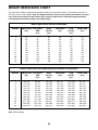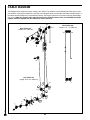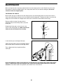
1
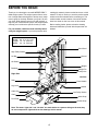
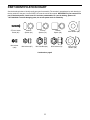
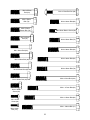
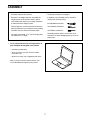
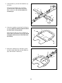
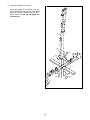
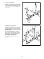
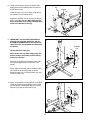
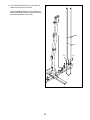
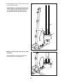
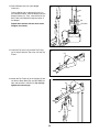
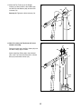
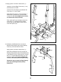
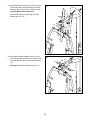
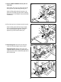
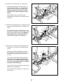
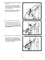
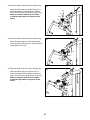
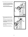
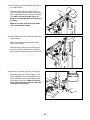
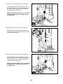
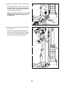
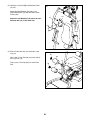
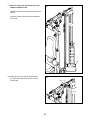
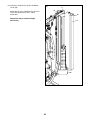
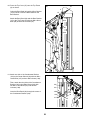
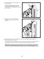
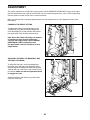
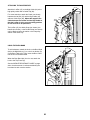
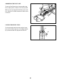
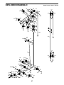
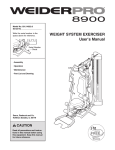
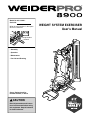
Model No. 831.14923.1 Serial No. Write the serial number in the space above for reference. Serial Number Decal • Assembly • Operation • Maintenance • Part List and Drawing Sears, Roebuck and Co. Hoffman Estates, IL 60179 CAUTION Read all precautions and instructions in this manual before using this equipment. Keep this manual for future reference. WEIGHT SYSTEM EXERCISER User’s Manual TABLE OF CONTENTS WARNING DECAL PLACEMENT . . . . . . . . . . . . . . . . . . . . . . . . . . . . . . . . . . . . . . . . . . . . . . . . . . . . . . . . . . . . . . . 2 IMPORTANT PRECAUTIONS . . . . . . . . . . . . . . . . . . . . . . . . . . . . . . . . . . . . . . . . . . . . . . . . . . . . . . . . . . . . . . . . . . 3 BEFORE YOU BEGIN. . . . . . . . . . . . . . . . . . . . . . . . . . . . . . . . . . . . . . . . . . . . . . . . . . . . . . . . . . . . . . . . . . . . . . . . 4 PART IDENTIFICATION CHART. . . . . . . . . . . . . . . . . . . . . . . . . . . . . . . . . . . . . . . . . . . . . . . . . . . . . . . . . . . . . . . . 5 ASSEMBLY . . . . . . . . . . . . . . . . . . . . . . . . . . . . . . . . . . . . . . . . . . . . . . . . . . . . . . . . . . . . . . . . . . . . . . . . . . . . . . . . 7 ADJUSTMENT . . . . . . . . . . . . . . . . . . . . . . . . . . . . . . . . . . . . . . . . . . . . . . . . . . . . . . . . . . . . . . . . . . . . . . . . . . . . 35 WEIGHT RESISTANCE CHART . . . . . . . . . . . . . . . . . . . . . . . . . . . . . . . . . . . . . . . . . . . . . . . . . . . . . . . . . . . . . . . 38 CABLE DIAGRAM . . . . . . . . . . . . . . . . . . . . . . . . . . . . . . . . . . . . . . . . . . . . . . . . . . . . . . . . . . . . . . . . . . . . . . . . . . 39 MAINTENANCE . . . . . . . . . . . . . . . . . . . . . . . . . . . . . . . . . . . . . . . . . . . . . . . . . . . . . . . . . . . . . . . . . . . . . . . . . . . 41 EXERCISE GUIDELINES . . . . . . . . . . . . . . . . . . . . . . . . . . . . . . . . . . . . . . . . . . . . . . . . . . . . . . . . . . . . . . . . . . . . 42 PART LIST . . . . . . . . . . . . . . . . . . . . . . . . . . . . . . . . . . . . . . . . . . . . . . . . . . . . . . . . . . . . . . . . . . . . . . . . . . . . . . . 43 EXPLODED DRAWING. . . . . . . . . . . . . . . . . . . . . . . . . . . . . . . . . . . . . . . . . . . . . . . . . . . . . . . . . . . . . . . . . . . . . . 45 ORDERING REPLACEMENT PARTS. . . . . . . . . . . . . . . . . . . . . . . . . . . . . . . . . . . . . . . . . . . . . . . . . . . Back Cover 90 DAY FULL WARRANTY . . . . . . . . . . . . . . . . . . . . . . . . . . . . . . . . . . . . . . . . . . . . . . . . . . . . . . . . . . . Back Cover WARNING DECAL PLACEMENT This drawing shows the location(s) of the warning decal(s). If a decal is missing or illegible, call 1-877-992-5999 and request a free replacement decal. Apply the decal in the location shown. Note: The decal(s) may not be shown at actual size. 2 IMPORTANT PRECAUTIONS WARNING: To reduce the risk of serious injury, read all important precautions and instructions in this manual and all warnings on your weight system before using your weight system. Sears assumes no responsibility for personal injury or property damage sustained by or through the use of this product. 1. It is the responsibility of the owner to ensure that all users of the weight system are adequately informed of all precautions. 10. Wear appropriate exercise clothes while exercising; do not wear loose clothes that could become caught on the weight system. Always wear athletic shoes for foot protection. 2. Before beginning any exercise program, consult your physician. This is especially important for persons over age 35 or persons with pre-existing health problems. 11. Keep hands and feet away from moving parts. 12. Always secure the weight stack with the lock pin and the lock after exercising to prevent unauthorized use of the weight system (see LOCKING THE WEIGHT STACK on page 37). 3. Use the weight system only as described in this manual. 4. The weight system is intended for home use only. Do not use the weight system in a commercial, rental, or institutional setting. 13. Make sure that the cables remain on the pulleys at all times. If the cables bind while you are exercising, stop immediately and make sure that the cables are on the pulleys. 5. Keep the weight system indoors, away from moisture and dust. Do not put the weight system in a garage or covered patio, or near water. 14. Always stand on the foot plate when performing an exercise that could cause the weight system to tip. 6. Place the weight system on a level surface, with a mat beneath it to protect the floor or carpet. Make sure that there is enough clearance around the weight system to mount, dismount, and use the weight system. 15. Never release the arms, leg lever, lat bar, handle, ankle strap, or double strap while weights are raised. The weights will fall with great force. 7. Inspect and properly tighten all parts regularly. Replace any worn parts immediately. 16. Always disconnect the lat bar from the weight system when performing an exercise that does not require the lat bar. 8. Keep children under age 12 and pets away from the weight system at all times. 17. Over exercising may result in serious injury or death. If you feel faint or if you experience pain while exercising, stop immediately and cool down. 9. The weight system should not be used by persons weighing more than 300 lbs. (136 kg). 3 BEFORE YOU BEGIN Thank you for selecting the versatile WEIDER PRO™ 8900 weight system. The weight system offers a selection of weight stations designed to develop every major muscle group of the body. Whether your goal is to tone your body, build dramatic muscle size and strength, or improve your cardiovascular system, the weight system will help you to achieve the specific results you want. reading this manual, please see the back cover of this manual. To help us assist you, note the product model number and serial number before contacting us. The model number and the location of the serial number decal are shown on the front cover of this manual. Before reading further, please review the drawing below and familiarize yourself with the parts that are labeled. For your benefit, read this manual carefully before using the weight system. If you have questions after Height: 6 ft. 11 in. (211 cm) Length: 7 ft. 1 in. (216 cm) Width: 4 ft. 1 in. (124 cm) Burn Band High Pulley Station Lat Bar Shroud Ab Station Weight Backrest Weight Pin Butterfly Arm Right Side Left Side Seat Press Handle Leg Lever Handle Cable Clip Low Pulley Station Chain Ankle Strap Foot Plate Double Strap Note: The terms “right side” and “left side” are used relative to a person sitting on the seat; they do not correspond to right and left on the drawings in this manual. 4 PART IDENTIFICATION CHART See the drawings below to identify small parts used in assembly. The number in parentheses by each drawing is the key number of the part, from the PART LIST near the end of this manual. IMPORTANT: If you cannot find a part in the hardware kit, check to see if it has been preassembled. If a part is missing, please call 1-877-992-5999. To avoid damaging parts, do not use power tools for assembly. ST4.2 x 19mm Screw (90) M4 Locknut (108) 6.35mm Spacer (94) M6 Locknut (87) 12.7mm Spacer (73) M10 Jam Nut (99) 14.8mm Spacer (95) M10 Locknut (74) Continued on page 6 5 M10 Washer (88) M10 Curved Washer (86) M10 x 57mm Bolt (93) M10 x 57mm Bolt Set (80) M10 x 55mm Bolt (79) M10 x 63mm Bolt (89) M10 x 50mm Button Bolt (76) M8 x 65mm Button Screw (82) M10 x 47mm Bolt (91) M10 x 65mm Bolt (75) M10 x 68mm Bolt (66) M6 x 45mm Bolt (85) M10 x 93mm Bolt (63) M10 x 45mm Bolt (98) M10 x 95mm Bolt (78) M10 x 43mm Bolt (65) M10 x 97mm Bolt (100) M10 x 40mm Bolt (97) M10 x 117mm Bolt (64) M10 x 20mm Screw (84) M10 x 125mm Bolt (83) M6 x 16mm Screw (62) M10 x 130mm Bolt (11) M4 x 12mm Bolt (107) 6 ASSEMBLY • Assembly requires two persons. • To identify small parts, see page 5. • Because of its weight and size, assemble the weight system in the location where it will be used. Make sure that there is enough clearance to walk around the weight system. • In addition to the included tool(s), assembly requires the following tool(s): two adjustable wrenches • Place all parts in a cleared area and remove the packing materials. Do not dispose of the packing materials until you nish all assembly steps. one standard screwdriver • Left parts are marked “L” or “Left” and right parts are marked “R” or “Right.” Assembly may be easier if you have a set of wrenches. To avoid damaging parts, do not use power tools. one Phillips screwdriver 1. Go to www.weiderservice.com/registration on your computer and register your product. 1 • activates your warranty • saves you time if you ever need to contact Customer Care • allows us to notify you of upgrades and offers Note: If you do not have Internet access, call 1-877-992-5999 and register your product. 7 2. Orient the Base (1) and the Side Stabilizers (2) as shown. 2 Attach the Side Stabilizers (2) to the Base (1) with two M10 x 95mm Bolts (78) and two M10 Locknuts (74). Do not fully tighten the Locknuts yet. 2 74 1 74 78 2 78 Warning Decal 3. Orient the U-stabilizer (3) and the Foot Plate (4) as shown. Make sure that the textured side of the Foot Plate is facing upward. 3 3 82 Attach the Foot Plate (4) to the U-stabilizer (3) with two M8 x 65mm Button Screws (82). Do not overtighten the Screws; the Foot Plate must pivot easily. 4 82 4. Attach the U-stabilizer (3) to the Base (1) with two M10 x 68mm Bolts (66), two M10 Washers (88), and two M10 Locknuts (74). 4 74 1 3 74 88 66 8 88 5. Orient the Upright (5) as shown. 5 Attach the Upright (5) to the Base (1) and to the Side Stabilizers (2) with four M10 x 55mm Bolts (79), four M10 Washers (88), and four M10 Locknuts (74). Do not fully tighten the Locknuts yet. 5 74 74 74 2 2 1 88 79 9 88 79 6. Orient the Leg (10) as shown. 6 Attach the Leg (10) to the Base (1) with two M10 x 55mm Bolts (79), two M10 Washers (88), and two M10 Locknuts (74). Do not fully tighten the Locknuts yet. 10 74 74 1 88 88 79 7. Orient the Seat Tube (8) as shown. 7 74 Attach the Seat Tube (8) to the Leg (10) with two M10 x 68mm Bolts (66), two M10 Washers (88), and two M10 Locknuts (74). Do not fully tighten the Locknuts yet. 74 8 88 Next, attach the Seat Tube (8) to the Upright (5) with two M10 x 93mm Bolts (63), two M10 Washers (88), and two M10 Locknuts (74). Do not fully tighten the Locknuts yet. 74 10 5 74 See steps 2, 5, 6, and 7. Tighten the M10 Locknuts (74). 88 66 10 88 63 8. Using a plastic bag to keep your fingers clean, apply some of the included grease to an M10 x 57mm Bolt Set (80). 8 80 Grease 80 Orient the Leg Lever (13) so that the high end of the bracket is in the location shown. 13 10 Attach the Leg Lever (13) to the Leg (10) with the M10 x 57mm Bolt Set (80). Make sure that the barrel of the Bolt Set is inserted through both sides of the bracket on the Leg. High End 9. IMPORTANT: See the CABLE DIAGRAM on page 39. Cut along the dotted line, and lay the CABLE DIAGRAM beside this manual for reference while you assemble the cables and the pulleys. 9 74 Identify the Burn Cable (45). 45 Next, identify the four Burn Pulleys (68), the three V-pulleys (not shown), and the twenty Pulleys (not shown). Threaded End 1 73 68 Route the threaded end of the Burn Cable (45) through the large bracket on the Base (1) as shown. 73 89 Attach a Burn Pulley (68) above the Burn Cable (45) inside the large bracket with an M10 x 63mm Bolt (89), two 12.7mm Spacers (73), and an M10 Locknut (74). 10. Attach a second Burn Pulley (68) above the Burn Cable (45) inside the large bracket on the Base (1) with an M10 x 63mm Bolt (89), two 12.7mm Spacers (73), and an M10 Locknut (74). 10 74 45 73 1 68 73 89 11 11. Orient the Weight Guides (31) so that the indicated holes are closer to the floor. 11 Insert the Weight Guides (31) into the Base (1). Attach each Weight Guide with an M10 x 63mm Bolt (89) and an M10 Locknut (74). Holes 31 74 74 1 89 12 12. Orient the Bottom Cover (28) so that the notch is in the indicated location. 12 Slide the Bottom Cover (28) downward over the Weight Guides (31) and the Burn Cable (45) as shown. Make sure that the Burn Cable is in the indicated notch in the Bottom Cover. 31 45 Notch 28 13. Make sure that the Burn Cable (45) is routed as shown. 13 Attach the Bottom Cover (28) to the Base (1) with two ST4.2 x 19mm Screws (90). 90 1 28 45 13 14. Slide a Bumper (40) onto each Weight Guide (31). 14 31 Orient a Weight (30) so that the pin hole is in the indicated location. Slide the Weight onto the Weight Guides (31). Then, route the end of the Burn Cable (45) upward through the center of the Weight. 45 30 Pin Hole Repeat these actions with the other eleven Weights (not shown). 40 15. Orient the Top Cover (27) and the Top Frame (6) as shown. Slide the Top Cover onto the Top Frame. 15 27 6 16. Attach the Top Frame (6) to the Upright (5) with two M10 x 93mm Bolts (63), two M10 Washers (88), and two M10 Locknuts (74). Do not fully tighten the Locknuts yet. 16 74 88 6 63 63 14 5 17. Attach the Top Frame (6) to the Weight Guides (31) with two M10 x 43mm Bolts (65), two M10 Curved Washers (86), and two M10 Locknuts (74). 17 74 86 86 See step 16. Tighten the M10 Locknuts (74). 6 65 65 31 18. Note: For clarity, the Top Cover (27) is not shown in this step. 18 74 Route the eyelet end of the Burn Cable (45) over two Burn Pulleys (68) as shown. 68 68 Attach each Burn Pulley (68) to the indicated side of the Top Frame (6) with an M10 x 40mm Bolt (97) and an M10 Locknut (74). 6 45 97 Eyelet End 15 19. Apply grease to an M10 x 130mm Bolt (11). 19 Identify the Left and Right Press Arms (17, 18) and orient them as shown. Insert the Press Arm Spacer (42) between the Press Arms (17, 18) as shown. Attach the Press Arms (17, 18) to the Base (1) with the M10 x 130mm Bolt (11) and an M10 Locknut (74). Do not overtighten the Locknut; the Press Arms must pivot easily. 18 Then, attach the Press Arm Spacer (42) to the Press Arms (17, 18) with two M10 x 20mm Screws (84), two M10 Washers (88), and the Press Arm Spacer (42). 84 88 42 74 88 84 1 17 Grease 20. Identify the Left Butterfly Arm (15), the Left Butterfly Pulley Bracket (20), and the Butterfly Frame (7), and orient them as shown. 11 20 21 74 16 Apply grease to an M10 x 130mm Bolt (11). 52 20 Attach the Left Butterfly Arm (15) and the Left Butterfly Pulley Bracket (20) to the indicated side of the Butterfly Frame (7) with the M10 x 130mm Bolt (11), an Upper Butterfly Bushing (52), and an M10 Locknut (74). Do not overtighten the Locknut; the Butterfly Arm must pivot easily. 7 Grease 11 Repeat this step to attach the Right Butterfly Arm (16) and the Right Butterfly Pulley Bracket (21). 16 15 21. Attach the Butterfly Frame (7) to the Top Frame (6) with two M10 x 93mm Bolts (63), two M10 Washers (88), and two M10 Locknuts (74). Do not fully tighten the Locknuts yet. 21 63 6 Insert a Ball Detent Assembly (96) into each Butterfly Arm (15, 16). 88 16 96 96 15 7 74 22. Finish attaching the Butterfly Frame (7) to the Top Frame (6) with two M10 x 117mm Bolts (64), four M10 Washers (88), and two M10 Locknuts (74). 22 88 74 6 88 See step 21. Tighten the M10 Locknuts (74). 64 7 17 23. See the CABLE DIAGRAM. Identify the Low Cable (43). 23 10 Route either end of the Low Cable (43) through the Leg Lever (13) and through the Leg (10). 13 Attach a Pulley (69) inside the Leg Lever (13) above the Low Cable (43) with an M10 x 63mm Bolt (89), two 12.7mm Spacers (73), and an M10 Locknut (74). 74 73 73 69 89 43 24. Pivot the Leg Lever (13) away from the Leg (10). 24 10 Attach a Pulley (69) inside the Leg (10) under the Low Cable (43) with an M10 x 65mm Bolt (75), two M10 Washers (88), two 12.7mm Spacers (73), and an M10 Locknut (74). 13 74 43 88 73 69 73 88 25. See drawing 25a. Route the Low Cable (43) under the Press Arm Spacer (42) as shown. 25a See drawing 25b. Attach a Pulley (69) to the indicated bracket on the Base (1) above the Low Cable (43) with an M10 x 45mm Bolt (98) and an M10 Jam Nut (99). 43 42 25b 69 43 99 1 98 18 75 26. Route the Low Cable (43) over a Pulley (69). 26 Attach the Pulley (69) and a Cable Trap (71) between the Press Arms (17, 18) with an M10 x 125mm Bolt (83) and an M10 Washer (88). Make sure that the Cable Trap is oriented to hold the Low Cable in the groove of the Pulley. 71 83 69 43 88 18 Note: Another Pulley (not shown) will be attached with the same M10 x 125mm Bolt (83) in step 28. 17 27. Route the Low Cable (43) over a Pulley (69) and through the indicated bracket on the Base (1) as shown. 27 69 43 Attach the Pulley (69) and a Cable Trap (71) to the bracket on the Base (1) with an M10 x 47mm Bolt (91) and an M10 Locknut (74). Make sure that the Cable Trap is oriented to hold the Low Cable in the groove of the Pulley. 74 1 71 91 28. Route the Low Cable (43) upward between the Press Arms (17, 18) and over a Pulley (69) as shown. 28 Partially pull out the indicated M10 x 125mm Bolt (83) until you can hold the Pulley (69) and a Cable Trap (71) between the Press Arms (17, 18). 43 69 5 71 83 Then, fully insert the M10 x 125mm Bolt (83) and tighten an M10 Locknut (74) and an M10 Washer (88) onto it. Make sure that the Cable Trap (71) is oriented to hold the Low Cable in the groove of the Pulley (69). 18 88 74 17 Then, route the Low Cable (43) through the indicated side of the Upright (5). Note: You will nish routing the Low Cable (43) in later steps. 19 29. See the CABLE DIAGRAM. Identify the High Cable (44). 29 Route the High Cable (44) upward through the Top Frame (6) and over a Pulley (69). Make sure that the eyelet end of the High Cable is in the location shown. 69 74 Attach the Pulley (69) inside the Top Frame (6) with an M10 x 68mm Bolt (66), two 14.8mm Spacers (95), and an M10 Locknut (74). 6 95 95 66 44 Eyelet End 30. Route the High Cable (44) over a Pulley (69). 30 Attach the Pulley (69) and a Cable Trap (71) to the indicated side of the Top Frame (6) with an M10 x 93mm Bolt (63), an M10 Washer (88), and an M10 Locknut (74). Make sure that the Cable Trap is oriented to hold the High Cable in the groove of the Pulley. 74 71 69 6 44 88 31. Route the High Cable (44) under a V-pulley (67). 31 Attach the V-pulley (67) and a Cable Trap (71) to the Upright (5) with an M10 x 57mm Bolt (93) and an M10 Locknut (74). Make sure that the Cable Trap is oriented to hold the High Cable in the groove of the V-pulley. 93 71 44 67 5 74 20 63 32. Route the High Cable (44) around a Pulley (69). 32 Attach the Pulley (69) and a Cable Trap (71) to the Right Butterfly Pulley Bracket (21) with an M10 x 47mm Bolt (91) and an M10 Locknut (74). Make sure that the Cable Trap is oriented to hold the High Cable in the groove of the Pulley. 74 71 69 21 44 91 33. Route the High Cable (44) around a Pulley (69). 33 Attach the Pulley (69) to the indicated bracket on the Upright (5) with an M10 x 43mm Bolt (65) and an M10 Locknut (74). 74 5 69 65 44 34. Route the High Cable (44) around a Pulley (69). 34 Attach the Pulley (69) and a Cable Trap (71) to the Left Butterfly Pulley Bracket (20) with an M10 x 47mm Bolt (91) and an M10 Locknut (74). Make sure that the Cable Trap is oriented to hold the High Cable in the groove of the Pulley. 74 71 20 69 91 21 44 35. Route the High Cable (44) under a V-pulley (67). 35 Attach the V-pulley (67) and a Cable Trap (71) to the Upright (5) with an M10 x 57mm Bolt (93) and an M10 Locknut (74). Make sure that the Cable Trap is oriented to hold the High Cable in the groove of the V-pulley. 27 Slot 74 Then, route the High Cable (44) through the opening in the Top Cover (27) as shown. 71 67 93 44 5 36. Note: For clarity, the Top Cover (27) is not shown in this step. Slide the Top Cover as far as possible in the direction indicated by the arrow. 36 74 88 Route the High Cable (44) upward through the Top Frame (6), over a Pulley (69), and downward through the Top Frame as shown. Make sure to leave slack in the High Cable in the indicated location. 69 73 6 73 88 75 44 Attach the Pulley (69) inside the Top Frame (6) with an M10 x 65mm Bolt (75), two M10 Washers (88), two 12.7mm Spacers (73), and an M10 Locknut (74). Note: Another Pulley (not shown) will be attached inside the Top Frame (6) in step 62. Slack 22 37. Hold a Pulley (69) under the High Cable (44) in the location shown. 37 74 88 Attach the Pulley (69) and a Cable Trap (71) to the Top Frame (6) with an M10 x 93mm Bolt (63), an M10 Washer (88), and an M10 Locknut (74). Make sure that the Cable Trap is oriented to hold the High Cable in the groove of the Pulley. 6 69 71 63 44 Make sure to leave slack in the High Cable (44) in the indicated location. Slack 38. Hold a Pulley (69) in the slack in the High Cable (44) as shown. 38 Have a second person orient the two Pulley Plates (70) as shown. Attach the Pulley (69) to the second hole from the upper end of the Pulley Plates (70) with an M10 x 43mm Bolt (65) and an M10 Locknut (74). 44 74 65 69 70 39. Route the Low Cable (43) under a Pulley (69). 39 Attach the Pulley (69), a Cable Trap (71), and two Half Guards (72) to the Upright (5) with an M10 x 97mm Bolt (100), an M10 Washer (88), and an M10 Locknut (74). Make sure that the Cable Trap is oriented to hold the Low Cable in the groove of the Pulley. 5 74 88 72 43 71 72 69 23 100 40. Route the Low Cable (43) under a Pulley (69). 40 Attach the Pulley (69), a Cable Trap (71), and two Half Guards (72) to the indicated bracket on the Base (1) with an M10 x 50mm Button Bolt (76) and an M10 Locknut (74). 69 Make sure that the Cable Trap (71) is oriented to hold the Low Cable (43) in the groove of the Pulley (69). 74 72 43 71 72 76 1 41. Route the Low Cable (43) over a Pulley (69). 41 Attach the Pulley (69) to the lowest hole in the Pulley Plates (70) with an M10 x 43mm Bolt (65) and an M10 Locknut (74). 70 74 65 69 43 42. Route the Low Cable (43) under a Pulley (69). 42 Attach the Pulley (69), a Cable Trap (71), and two Half Guards (72) to the indicated bracket on the Base (1) with an M10 x 50mm Button Bolt (76) and an M10 Locknut (74). 69 43 74 Make sure that the Cable Trap (71) is oriented to hold the Low Cable (43) in the groove of the Pulley (69). 72 71 72 1 24 76 43. Route the Low Cable (43) under a Pulley (69). 43 Attach the Pulley (69), a Cable Trap (71), and two Half Guards (72) to the indicated bracket on the Base (1) with an M10 x 50mm Button Bolt (76) and an M10 Locknut (74). 43 74 Make sure that the Cable Trap (71) is oriented to hold the Low Cable (43) in the groove of the Pulley (69). 69 72 71 72 1 76 44. Route the Low Cable (43) through the Upright (5) as shown. 44 Attach a V-pulley (67) inside the Upright (5) under the Low Cable (43) with an M10 x 65mm Bolt (75), two M10 Washers (88), two 6.35mm Spacers (94), and an M10 Locknut (74). 5 43 74 88 88 94 67 25 75 94 45. Orient the Weight Selector (32) as shown. 45 Tighten the lower end of the Burn Cable (45) completely into the lower end of the Weight Selector (32). 44 A 45 Next, insert the end of the High Cable (44) through the upper end of the Burn Cable (45), and tighten the High Cable at least five complete turns into the Weight Selector (32). Then, tighten the Nut (A) against the Burn Cable (45), and tighten the Nut (B) against the Weight Selector (32). 32 45 B 46. Insert the Weight Selector (32) into the stack of Weights (30). 46 30 Lift the top Weight (30), and tap a Roll Pin (37) into the indicated hole in the Weight Selector (32). 32 Hole 37 30 26 47. Insert the Weight Pin (41) under a Weight (30). 47 30 41 48. Insert the Lock Pin (39) through a Weight Guide (31), and secure the Lock (38) into the Lock Pin. 48 31 38 39 49. Orient the Seat (24) and a Cushion Frame (9) as shown. 49 24 Attach the Seat (24) to the Cushion Frame (9) with four M6 x 16mm Screws (62). 9 62 27 62 50. Insert the Cushion Frame (9) into the Seat Tube (8). 50 Tighten an Adjustment Knob (29) into the Seat Tube (8) and into one of the holes in the Cushion Frame (9). Make sure that the Adjustment Knob is engaged in a hole. 9 8 29 51. Slide a Foam Pad (35) onto each side of the Leg Lock Frame (12). Then, press a Pad Cap (36) into each Foam Pad. 51 36 35 12 35 36 52. Insert the Leg Lock Frame (12) into the indicated bracket on the Upright (5). 52 Tighten an Adjustment Knob (29) into the Upright (5) and into one of the holes in the Leg Lock Frame (12). Make sure that the Adjustment Knob is engaged in a hole. 5 12 28 29 53. Orient the Backrest (25) and a Cushion Frame (9) as shown. 53 Attach the Backrest (25) to the Cushion Frame (9) with four M6 x 16mm Screws (62). 9 62 25 62 54. Insert the Cushion Frame (9) into the Upright (5). 54 5 Tighten an Adjustment Knob (29) into the Upright (5) and into one of the holes in the Cushion Frame (9). Make sure that the Adjustment Knob is engaged in a hole. 9 29 29 55. Identify the Left and Right and Butterfly Pads (22, 23). 55 Attach the Right Butterfly Pad (23) to the Right Butterfly Arm (16) with two M6 x 16mm Screws (62). 23 16 Attach the Left Butterfly Pad (22) to the Left Butterfly Arm (15) in the same way. 15 62 22 56. Slide a Foam Pad (35) onto each side of the Leg (10). 56 36 35 Next, slide a Foam Pad (35) onto each side of the Leg Lever (13). 10 Then, press a Pad Cap (36) into each Foam Pad. 35 36 35 36 13 35 36 30 57. Note: For clarity, the Top Cover (27) is not shown in steps 57 to 59. 57 Identify the Center Shroud (33), and orient it as shown. Insert the Center Shroud (33) into the Bottom Cover (28). 33 28 58. Attach the top of the Center Shroud (33) to the Top Frame (6) with two ST4.2 x 19mm Screws (90). 58 90 6 90 33 31 59. Insert the Left Shroud (110) into the Bottom Cover (28). 59 6 34 Attach the top of the Left Shroud (110) to the Top Frame (6) with an ST4.2 x 19mm Screw (90). 90 Repeat this step to attach the Right Shroud (34). 110 28 32 60. Press the Top Cover (27) onto the Top Frame (6) as shown. 60 27 6 Orient the Burn Band (26) and the Burn Bracket (14) as shown. Insert the Burn Band into the Burn Bracket. 87 Attach the Burn Band (26) and the Burn Bracket (14) to the Top Frame (6) with two M6 x 45mm Bolts (85) and two M6 Locknuts (87). 14 85 26 61. Attach one side of the Containment Bracket (109) to the Center Shroud (33) with two M4 x 12mm Bolts (107) and two M4 Locknuts (108). 61 Then, attach the other side of the Containment Bracket (109) to the Right Shroud (34) with two M4 x 12mm Bolts (107) and two M4 Locknuts (108). 26 34 108 Insert the Burn Band (26) through the center of the Containment Bracket (109). 108 109 107 33 33 107 62. Insert a Pulley (69) under the High Cable (44) in the location shown. 62 74 88 Attach the Pulley (69) inside the Top Frame (6) with an M10 x 65mm Bolt (75), two M10 Washers (88), two 12.7mm Spacers (73), and an M10 Locknut (74). 69 44 73 6 73 88 75 63. Attach the hook on the Burn Band (26) to the High or Low Anchor (C, D) on the Burn Cable (45). 63 26 45 Hook C D 64. Make sure that all parts are properly tightened. The use of the remaining parts will be explained in ADJUSTMENT, beginning on page 35. Before using the weight system, pull each cable a few times to make sure that the cables move smoothly around the pulleys. If one of the cables does not move smoothly, find and correct the problem. IMPORTANT: If the cables are not properly installed, they may be damaged when heavy weight is used. See the CABLE DIAGRAM on page 39 for proper cable routing. If there is any slack in the cables, you will need to remove the slack by tightening the cables. See MAINTENANCE on page 41. 34 ADJUSTMENT This section explains how to adjust the weight system. See the EXERCISE GUIDELINES on page 42 for important information about how to get the most benefit from your exercise program. Also, refer to the accompanying exercise guide to see the correct form for several exercises. Make sure that all parts are properly tightened each time the weight system is used. Replace any worn parts immediately. CHANGING THE WEIGHT SETTING To change the setting of the weight stack, insert a Weight Pin (41) under the desired Weight (30). Insert the Weight Pin so that the bent end touches the weight stack. Turn the bent end downward. Note: Due to the cables and pulleys, the amount of resistance at each exercise station may vary from the weight setting. Use the WEIGHT RESISTANCE CHART on page 38 to find the approximate amount of resistance at each weight station. 30 41 ADJUSTING THE SEAT, THE BACKREST, AND THE LEG LOCK FRAME 25 To adjust the Seat (24), remove the Adjustment Knob (29), move the Seat to the desired position, and then tighten the Adjustment Knob into the Seat Tube (8) and one of the holes in the Cushion Frame (not shown). Make sure that the Adjustment Knob is engaged in a hole. 24 12 29 Adjust the Backrest (25) and the Leg Lock Frame (12) in the same way. 8 29 35 ATTACHING THE ACCESSORIES Attach the Lat Bar (47) to the High Cable (44) at the high pulley station with a Cable Clip (50). For some exercises, attach the Chain (not shown) between the Lat Bar (47) and the High Cable (44) with two Cable Clips (50). Adjust the length of the Chain between the Lat Bar and the High Cable so that the Lat Bar is in the correct starting position for the exercise to be performed. 44 50 47 The Lat Bar (47), the Ankle Strap (not shown), the Handle (not shown), or the Double Strap (not shown) can be attached at the ab station or the low pulley station in the same way. USING THE BURN BAND To add resistance, attach the hook on the Burn Band (26) to the High Anchor (C) or to the Low Anchor (D) on the Burn Cable (45). Then, insert the Burn Cable into the slot on the Burn Band. 6 When the Burn Band (26) is not in use, attach the hook to the Top Frame (6). See the WEIGHT RESISTANCE CHART on page 38 to view the amount of resistance added by the burn band at each exercise station. 26 45 Slot Hook C D 36 CONVERTING THE FOOT PLATE To use the Foot Plate (4) as a footrest while using the low pulley station, rotate the Foot Plate upward. When you are not using the Foot Plate (4) as a footrest, rotate the Foot Plate downward so that it is flat on the floor. 4 LOCKING THE WEIGHT STACK To lock the weight stack after each workout, insert the Lock Pin (39) through one of the Weight Guides (31), and secure the Lock (38) into the Lock Pin. 31 38 39 37 WEIGHT RESISTANCE CHART The chart below shows the approximate weight resistance at each exercise station. The numbers in the left column refer to the 12.5-lb. weights. Note: The weight resistance shown for the butterfly arm station is for each arm. The actual resistance at each station may vary due to differences in individual weights as well as friction between the cables, pulleys, and weight guides. WEIGHT RESISTANCE WITHOUT BURN BAND WEIGHT AB STATION BUTTERFLY (lbs.) ARM (lbs.) 1 2 3 4 5 6 7 8 9 10 11 12 20 36 44 66 78 86 105 118 131 141 163 172 17 27 38 45 58 64 76 83 100 112 123 134 HIGH PULLEY (lbs.) LEG LEVER (lbs.) LOW PULLEY (lbs.) PRESS ARM (lbs.) 22 39 54 69 79 96 117 137 146 168 182 208 38 69 87 112 135 173 177 196 205 231 262 280 25 38 52 67 82 98 125 148 160 172 193 201 26 36 51 57 69 82 93 105 117 128 142 162 WEIGHT RESISTANCE WITH BURN BAND (HIGH ANCHOR / LOW ANCHOR) WEIGHT 1 2 3 4 5 6 7 8 9 10 11 12 AB STATION BUTTERFLY (lbs.) ARM (lbs.) 98 / 126 112 / 139 126 / 151 140 / 172 149 / 181 164 / 191 172 / 210 186 / 227 194 / 222 221 / 250 230 / 267 248 / 273 48 / 64 57 / 77 65 / 83 70 / 90 80 / 98 87 / 109 98 / 122 110 / 130 114 / 136 131 / 149 144 / 159 156 / 176 HIGH PULLEY (lbs.) LEG LEVER (lbs.) LOW PULLEY (lbs.) PRESS ARM (lbs.) 107 / 129 138 / 160 147 / 176 160 / 187 169 / 198 184 / 208 202 / 218 213 / 244 222 / 261 239 / 271 256 / 284 269 / 310 88 / 121 109 / 141 118 / 163 139 / 188 158 / 195 182 / 212 192 / 224 207 / 269 244 / 291 248 / 320 272 / 339 286 / 362 115 / 138 130 / 152 139 / 166 156 / 180 166 / 198 183 / 208 196 / 228 212 / 241 222 / 269 238 / 273 244 / 295 260 / 309 85 / 107 98 / 117 108 / 131 120 / 145 135 / 158 143 / 163 158 / 182 166 / 189 180 / 194 189 / 212 199 / 226 210 / 237 Note: 1 lb. = 0.45 kg 38 CABLE DIAGRAM The diagram below shows the proper routing of the cables. The numbers in each drawing show the proper route of that cable. Cut along the dotted line, and refer to this diagram while you assemble the cables and the pulleys. If the cables and the pulleys are not assembled correctly, the weight system will not function properly and damage may occur. Make sure that the cable traps do not touch or bind the cables. After you assemble the weight system, save this diagram with this manual for future reference. 10 2 11 8 High Cable (44) Length: 14 ft. (427 cm) Burn Cable (45) Length: 11 ft. 1 in. (338 cm) 3 4 3 1 4 9 7 5 6 9 12 Low Cable (43) Length: 22 ft. 6 in. (686 cm) 10 11 7 5 4 8 2 1 6 3 39 2 1 NOTES 40 MAINTENANCE Make sure that all parts are properly tightened each time the weight system is used. Replace any worn parts immediately. To clean the weight system, use a damp cloth and a mild, non-abrasive detergent; do not use solvents to clean the weight system. TIGHTENING THE CABLES Woven cable, the type of cable used on the weight system, can stretch slightly when it is first used. If there is slack in the cables before resistance is felt, the cables should be tightened. To tighten the cables, first insert the weight pin into the middle of the weight stack. Slack can be removed from the cables several ways: Remove an M10 Locknut (74) and an M10 x 43mm Bolt (65) from two Pulley Plates (70) and a Pulley (69). 44 Reattach the Pulley (69) to a hole closer to the center of the Pulley Plates (70). Make sure that the Cable (43, 44) and Pulleys move smoothly. 74 70 65 69 43 Loosen the Nut (A) on the High Cable (44). Tighten the High Cable (44) into the Weight Selector (32) until the slack is removed from the High Cable. Then, retighten the Nut (A) against the Burn Cable (45). 44 A 45 32 Do not overtighten the cables. If the cables are overtightened, the top weight will be lifted off the weight stack. If a cable tends to slip off the pulleys often, it may have become twisted. Remove the cable and reinstall it. If the cables need to be replaced, see the back cover of this manual. 41 EXERCISE GUIDELINES FOUR TYPES OF STRENGTH WORKOUTS workout, and the numbers of repetitions and sets to complete. Progress at your own pace and be sensitive to your body’s signals. Follow each workout with at least one day of rest. Note: A “repetition” is one complete cycle of an exercise, such as one sit-up. A “set” is a series of repetitions. Warming Up—Start with 5 to 10 minutes of stretching and light exercise. A warm-up increases your body temperature, heart rate, and circulation in preparation for exercise. Muscle Building—Work your muscles near their maximum capacity and progressively increase the intensity of your exercise. Adjust the intensity level of an individual exercise as follows: • Change the amount of resistance used. • Change the number of repetitions or sets performed. Working Out—Include 6 to 10 different exercises in each workout. Select exercises for every major muscle group, emphasizing areas that you want to develop. To give balance and variety to your workouts, vary the exercises from workout to workout. Use your own judgment to determine the amount of resistance that is right for you. Begin with 3 sets of 8 repetitions for each exercise you perform. Rest for 3 minutes after each set. When you can complete 3 sets of 12 repetitions without difficulty, increase the amount of resistance. Cooling Down—Finish with 5 to 10 minutes of stretching. Stretching increases the flexibility of your muscles and helps to prevent post-exercise problems. Toning—Tone your muscles by working them to a moderate percentage of their capacity. Select a moderate amount of resistance and increase the number of repetitions in each set. Complete as many sets of 15 to 20 repetitions as possible without discomfort. Rest for 1 minute after each set. Work your muscles by completing more sets rather than by using high amounts of resistance. EXERCISE FORM Move through the full range of motion for each exercise and move only the appropriate parts of the body. Perform the repetitions in each set smoothly and without pausing. The exertion stage of each repetition should last about half as long as the return stage. Exhale during the exertion stage of each repetition and inhale during the return stroke. Never hold your breath. Weight Loss—To lose weight, use a low amount of resistance and increase the number of repetitions in each set. Exercise for 20 to 30 minutes, resting for a maximum of 30 seconds between sets. Rest for a short period of time after each set: • Muscle Building—Rest for three minutes after each set. • Toning—Rest for one minute after each set. • Weight Loss—Rest for 30 seconds after each set. Cross Training—Combine strength training and aerobic exercise by following this type of program: • Strength training workouts on Monday, Wednesday, and Friday. • 20 to 30 minutes of aerobic exercise on Tuesday and Thursday. • One full day of rest each week to give your body time to regenerate. STAYING MOTIVATED For motivation, keep a record of each workout. Write the date, the exercises performed, the resistance used, and the numbers of sets and repetitions completed. Record your weight and key body measurements once a month. To achieve good results, make exercise a regular and enjoyable part of your life. WORKOUT GUIDELINES Familiarize yourself with the equipment and learn the proper form for each exercise. Use your own judgment to determine the appropriate length of time for each 42 PART LIST Key No. Qty. 1 2 3 4 5 6 7 8 9 10 11 12 13 14 15 16 17 18 19 20 21 22 23 24 25 26 27 28 29 30 31 32 33 34 35 36 37 38 39 40 41 42 43 44 45 1 2 1 1 1 1 1 1 2 1 3 1 1 1 1 1 1 1 2 1 1 1 1 1 1 1 1 1 3 12 2 1 1 1 6 6 1 1 1 2 1 1 1 1 1 Model No. 831.14923.1 R0513A Description Key No. Qty. Base Side Stabilizer U-stabilizer Foot Plate Upright Top Frame Buttery Frame Seat Tube Cushion Frame Leg M10 x 130mm Bolt Leg Lock Frame Leg Lever Burn Bracket Left Buttery Arm Right Buttery Arm Left Press Arm Right Press Arm Press Handle Left Buttery Pulley Bracket Right Buttery Pulley Bracket Left Buttery Pad Right Buttery Pad Seat Backrest Burn Band Top Cover Bottom Cover Adjustment Knob Weight Weight Guide Weight Selector Center Shroud Right Shroud Foam Pad Pad Cap Roll Pin Lock Lock Pin Bumper Weight Pin Press Arm Spacer Low Cable High Cable Burn Cable 46 47 48 49 50 51 52 53 54 55 56 57 58 59 60 61 62 63 64 65 66 67 68 69 70 71 72 73 74 75 76 77 78 79 80 81 82 83 84 85 86 87 88 89 90 43 1 1 1 1 3 6 2 10 2 6 2 8 3 4 6 2 12 8 2 5 5 3 4 20 2 13 8 12 54 4 3 7 2 6 1 4 2 1 2 2 2 2 35 5 6 Description Double Strap Lat Bar Chain Ankle Strap Cable Clip Composite Bushing Upper Buttery Bushing Large Round Cap Press Handle Foam Grip Small Round Cap Buttery Foam Grip Small Rectangular Cap Large Rectangular Cap Square Cap Foot U-stabilizer Cap M6 x 16mm Screw M10 x 93mm Bolt M10 x 117mm Bolt M10 x 43mm Bolt M10 x 68mm Bolt V-pulley Burn Pulley Pulley Pulley Plate Cable Trap Half Guard 12.7mm Spacer M10 Locknut M10 x 65mm Bolt M10 x 50mm Button Bolt ST4.2 x 16mm Screw M10 x 95mm Bolt M10 x 55mm Bolt M10 x 57mm Bolt Set M6 x 10mm Set Screw M8 x 65mm Button Screw M10 x 125mm Bolt M10 x 20mm Screw M6 x 45mm Bolt M10 Curved Washer M6 Locknut M10 Washer M10 x 63mm Bolt ST4.2 x 19mm Screw Key No. Qty. 91 92 93 94 95 96 97 98 99 100 101 102 3 1 2 2 2 2 2 1 1 1 2 1 Description Key No. Qty. M10 x 47mm Bolt Leg Lever Bumper M10 x 57mm Bolt 6.35mm Spacer 14.8mm Spacer Ball Detent Assembly M10 x 40mm Bolt M10 x 45mm Bolt M10 Jam Nut M10 x 97mm Bolt Lower Buttery Bushing Top Frame Cap 103 104 105 106 107 108 109 110 * * * * 2 2 2 1 4 4 1 1 – – – – Description Lat Bar Foam Grip Lat Bar Cap Plastic Bushing Handle M4 x 12mm Bolt M4 Locknut Containment Bracket Left Shroud User’s Manual Exercise Guide Grease Packet Assembly Tool Note: Specifications are subject to change without notice. For information about ordering replacement parts, see the back cover of this manual. If a part is missing, please call 1-877-992-5999. *These parts are not illustrated. 44 EXPLODED DRAWING A Model No. 831.14923.1 R0513A 63 104 74 86 74 74 86 88 103 27 6 47 88 48 87 87 102 65 14 103 52 53 85 104 21 101 16 57 74 96 7 74 107 64 50 57 56 62 55 11 9 74 24 62 25 59 23 52 11 20 62 53 29 29 15 51 74 56 55 74 59 58 22 29 74 74 58 66 74 74 59 8 51 88 92 88 66 53 63 88 74 74 62 62 74 10 96 12 80 57 101 59 57 9 77 108 5 88 74 13 106 26 63 51 51 85 107 109 108 63 88 57 46 74 74 60 77 60 2 1 74 51 89 78 77 28 88 51 49 88 88 79 88 78 2 88 74 79 45 58 60 77 62 90 53 EXPLODED DRAWING B Model No. 831.14923.1 R0513A 90 36 31 34 35 36 90 36 90 90 35 36 53 36 105 74 35 19 110 36 53 55 54 38 37 53 74 105 39 53 55 18 54 55 32 19 57 84 88 17 57 42 55 30 88 53 84 74 11 53 3 82 30 88 61 60 77 66 41 60 77 82 61 4 33 60 77 46 40 40 EXPLODED DRAWING C Model No. 831.14923.1 R0513A 74 74 88 69 74 71 69 88 63 93 74 88 68 88 73 71 74 95 67 74 69 95 66 71 67 69 68 75 88 69 74 69 73 88 73 74 71 97 63 71 93 69 65 65 71 69 69 91 81 70 91 69 70 81 65 44 45 88 74 67 94 88 94 75 74 43 74 72 74 73 68 73 69 71 72 89 69 71 74 74 73 69 69 73 72 99 89 88 69 76 71 72 69 69 98 75 74 76 74 73 73 72 69 69 71 71 88 72 88 72 88 83 68 73 100 69 72 71 71 91 88 74 47 76 90 DAY FULL WARRANTY If this Sears Weight System Exerciser fails due to a defect in material or workmanship within 90 days of the date of purchase, call 1-800-4-MY-HOME® (1-800-469-4663) to arrange for free repair (or replacement if repair proves impossible). This warranty does not apply when the Weight System Exerciser is used commercially or for rental purposes. This warranty gives you specific legal rights, and you may also have other rights which vary from state to state. Sears, Roebuck and Co., Hoffman Estates, IL 60179 Part No. 331524 R0513A Printed in China © 2012 ICON IP, Inc.