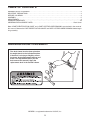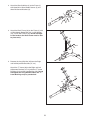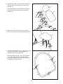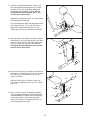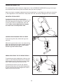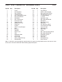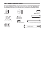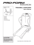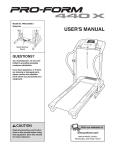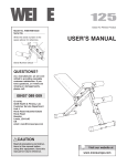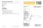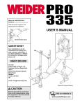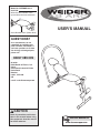
1
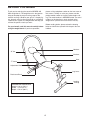
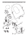
Model No. WEEMBE1326.0
Serial No.
Write the serial number in the
space above for future reference.
USER’S MANUAL
Serial Number Decal (Under Seat)
QUESTIONS?
As a manufacturer, we are
committed to providing complete customer satisfaction. If
you have questions, or if there
are missing or damaged parts,
please call:
08457 089 009
Or write:
ICON Health & Fitness, Ltd.
Unit 4
Revie Road Industrial Estate
Revie Road
Beeston
Leeds, LS118JG
UK
e-mail: [email protected]
CAUTION
Read all precautions and instructions in this manual before using
this equipment. Save this manual
for future reference.
Visit our website at
www.iconeurope.com
TABLE OF CONTENTS
WARNING DECAL PLACEMENT . . . . . . . . . . . . . . . . . . . . . . . . . . . . . . . . . . . . . . . . . . . . . . . . . . . . . . . . . . . . . 2
IMPORTANT PRECAUTIONS . . . . . . . . . . . . . . . . . . . . . . . . . . . . . . . . . . . . . . . . . . . . . . . . . . . . . . . . . . . . . . . . 3
BEFORE YOU BEGIN . . . . . . . . . . . . . . . . . . . . . . . . . . . . . . . . . . . . . . . . . . . . . . . . . . . . . . . . . . . . . . . . . . . . . . 4
ASSEMBLY . . . . . . . . . . . . . . . . . . . . . . . . . . . . . . . . . . . . . . . . . . . . . . . . . . . . . . . . . . . . . . . . . . . . . . . . . . . . . . .5
ADJUSTMENTS . . . . . . . . . . . . . . . . . . . . . . . . . . . . . . . . . . . . . . . . . . . . . . . . . . . . . . . . . . . . . . . . . . . . . . . . . . .9
EXERCISE GUIDELINES . . . . . . . . . . . . . . . . . . . . . . . . . . . . . . . . . . . . . . . . . . . . . . . . . . . . . . . . . . . . . . . . . . 10
ORDERING REPLACEMENT PARTS . . . . . . . . . . . . . . . . . . . . . . . . . . . . . . . . . . . . . . . . . . . . . . . . . .Back Cover
Note: A PART IDENTIFICATION CHART and a PART LIST/EXPLODED DRAWING are attached in the centre of
this manual. Remove the PART IDENTIFICATION CHART and PART LIST/EXPLODED DRAWING before beginning assembly.
WARNING DECAL PLACEMENT
The decal shown here has been placed on
the weight bench in the indicated location.
If the decal is missing or illegible, call our
Customer Service Department toll-free and
order a free replacement decal (see the
back cover of this manual). Apply the
replacement decal in the location shown.
WEIDER is a registered trademark of ICON IP, Inc.
2
IMPORTANT PRECAUTIONS
WARNING:
To reduce the risk of serious injury, read the following important precautions
before using the weight bench.
1. Read all instructions in this manual and all
warnings on the weight bench before using
the weight bench.
6. Keep children under the age of 12 and pets
away from the weight bench at all times.
7. Always wear athletic shoes for foot protection while exercising.
2. Use the weight bench only as described in
this manual.
8. Keep hands and feet away from moving parts.
3. It is the responsibility of the owner to ensure
that all users of the weight bench are adequately informed of all precautions.
9. The weight bench is designed to support a
maximum user weight of 115 kg (250 lbs.).
4. Keep the weight bench indoors, away from
moisture and dust. Place the weight bench
on a level surface, with a mat beneath it to
protect the floor or carpet. Make sure that
there is enough clearance around the weight
bench to mount, dismount, and use the
weight bench.
10. Inspect and tighten all parts each time the
weight bench is used. Replace any worn
parts immediately.
5. The weight bench is intended for home use
only. Do not use the weight bench in any
commercial, rental or institutional setting.
12. Use only the included resistance bands.
11. Always make sure that all pins are fully
inserted and are in the proper position for the
exercise you are performing.
13. If you feel pain or dizziness while exercising,
stop immediately and begin cooling down.
WARNING:
Before beginning this or any exercise program, consult your physician. This
is especially important for persons over the age of 35 or persons with pre-existing health problems.
Read all instructions before using. ICON assumes no responsibility for personal injury or property
damage sustained by or through the use of this product.
3
BEFORE YOU BEGIN
please call the telephone number on the front cover of
this manual. To help us assist you, please note the
product model number and serial number before calling. The model number is WEEMBE1326.0. The serial
number can be found on a decal attached to the
weight bench (see the front cover of this manual).
Thank you for selecting the versatile WEIDER® AB
ARC weight bench. The weight bench is designed to
help you develop the major muscle groups of the
stomach and legs. Whether your goal is a shapely figure, dramatic muscle size and strength, or a healthier
cardiovascular system, the weight bench will help you
achieve the specific results you want.
Before reading further, please review the drawing
below and familiarise yourself with the parts that are
labelled.
For your benefit, read this manual carefully before
using the weight bench. If you have questions,
Headrest
“U”-bar
Backrest
Seat
“T”-frame
Adjustment Knob
Leg Lever
Resistance Band
Levelling
Endcap
ASSEMBLED DIMENSIONS:
Height: 132 cm (52 in.)
Width: 79 cm (31 in.)
Depth: 152 cm (60 in.)
4
ASSEMBLY
• Tighten all parts as you assemble them, unless
instructed to do otherwise.
Make Things Easier for Yourself
Everything in this manual is designed to ensure
that the weight bench can be assembled successfully by anyone. Most people find that by
setting aside plenty of time, assembly will go
smoothly.
• As you assemble the weight bench, make sure all
parts are oriented as shown in the drawings.
• For help identifying small parts, use the PART
IDENTIFICATION CHART.
Before beginning assembly, carefully read the
following information and instructions:
In addition to the included tools, a rubber mallet
(not included) may be required for assembly.
• Assembly requires two persons.
Assembly will be more convenient if you have a
socket set, a set of open-end or closed-end
wrenches, or a set of ratchet wrenches.
• Place all parts in a cleared area and remove the
packing materials. Do not dispose of the packing
materials until assembly is completed.
1.
1
Before beginning assembly, make sure you
understand the information in the box
above. For help identifying small parts, use
the PART IDENTIFICATION CHART in the
centre of this manual.
1
Attach the Front Stabiliser (2) to the Frame (1)
with three M8 x 15mm Button Screws (5) and
three M8 Curved Washers (6).
5
6 5
6
5
2
5
2. Attach the Rear Stabiliser (3) to the Frame (1)
with three M8 x 15mm Button Screws (5) and
three M8 Curved Washers (6).
2
1
5
3
6
6
5
3. Attach the Back Frame (22) to the Frame (1) with
an M8 x 60mm Button Bolt (43), an M8 Washer
(33), and an M8 Locknut (34). Do not overtighten the Locknut; the Back Frame must be able
to pivot easily.
5
3
22
33
34
43
1
4. Remove the Long Bolt Set (25) from the Right
and Left Adjustment Brackets (27, 28).
4
Attach the “T”-frame (30) to the Right and Left
Adjustment Brackets (27, 28) with two “T”-frame
Bushings (29) and the Long Bolt Set (25). Do not
overtighten the Long Bolt Set. Note: The “T”frame Bushings may be preattached.
25
30
29
25
28
27
6
5. Attach the Headrest (17) to the Back Frame (22)
with four M6 x 15mm Screws (8) and four M6
Washers (7).
5
17
Attach the Backrest (16) to the Back Frame (22)
with four M6 x 15mm Screws (8) and four M6
Washers (7).
7
7
16
8
7
8
8
8
7 22
7
7
8
8
6. Attach the Seat (15) to the Frame (1) with four
M6 x 15mm Screws (8) and four M6 Washers (7).
7
7
8
6
15
7
8
7
8
7
8
1
7
8
7. Carefully roll both ends of the “U”-bar Pad (21) up
the “U”-bar (41) until the indicated holes are
exposed at each end of the “U”-bar.
7
21
Attach the Right and Left “L”-bars (18, 40) to the
“U”-bar (41) with four M5 x 15mm Flat Head
Screws (42). Roll the “U”-bar Pad (21) back over
the exposed Flat Head Screws.
42
41
40
42
Holes
18
7
8. Remove the indicated M10 Nylon Locknut (44)
from the Right Adjustment Bracket (27). Attach
the Right “L”-bar (18) to the Right Adjustment
Bracket with the M10 Nylon Locknut. Do not
overtighten the Nylon Locknut; the “L”-bar
must be able to pivot easily.
8
Repeat this step with the Left “L”-bar (40) and the
Left Adjustment Bracket (28).
20
19
Insert the Adjustment Knob (20) through the holes
in the Right and Left “L”-bars (18, 40) and the
Right and Left Adjustment Brackets (27, 28).
Tighten the Cap (19) onto the Adjustment Knob.
40
27
18
9. Attach the Leg Lever (46) to the Frame (1) with a
Short Bolt Set (24) and an M8 Washer (33). Next,
insert the Leg Lever Lock (38) into the indicated
hole in the Leg Lever and the Frame. Do not
overtighten the Short Bolt Set; the Leg Lever
must be able to pivot easily.
44
28
9
24
33
24
46
1
Hole
Hole
38
10. Insert the Pad Tube (13) into the indicated hole in
the Frame (1). Slide two Foam Pads (12) onto the
Pad Tube. Press two Medium Inner Caps (11)
into the Pad Tube.
10
12
13
Slide two Foam Pads (12) onto the Leg Lever
(46). Press two Medium Inner Caps (11) into the
Leg Lever.
11
12
46
11
1
12
11. Make sure that all parts are properly tightened.
The use of the remaining parts will be explained
in ADJUSTMENTS, beginning on the next page.
If the weight bench is not level on your floor,
rotate one or both of the Levelling Endcaps (4)
until the weight bench is level.
4
11
4
8
12
11
ADJUSTMENTS
This section explains how to adjust the weight bench. See the EXERCISE GUIDELINES on page 10 for important information about how to get the most benefit from your exercise program.
Make sure all parts are properly tightened each time the weight bench is used. Replace any worn parts immediately. The weight bench can be cleaned with a damp cloth and a mild, non-abrasive detergent. Do not use solvents.
ADJUSTING THE BACKREST
To adjust the Backrest (16), first remove the
Adjustment Pin (39). Raise or lower the Backrest, and
insert the Adjustment Pin through the “T”-frame (30)
and one of the holes in the Adjustment Tube (not
shown). Make sure the Adjustment Pin engages
one of the holes in the Adjustment Tube.
39
16
30
LOCKING AND UNLOCKING THE LEG LEVER
To use the Leg Lever (46), remove the Leg Lever
Lock (38).
When the Leg Lever (46) is not in use, insert the Leg
Lever Lock (38) into the Leg Lever and the Frame (1).
Make sure the Leg Lever Lock is fully inserted
into the Leg Lever and the Frame.
46
1
38
ADDING RESISTANCE TO THE WEIGHT BENCH
To add resistance to the weight bench, slide an included 5-lb. or 10-lb. Resistance Band (36 or 37) onto the
indicated tubes on each side of the rear of the weight
bench. Slide a Spring Clip (35) onto each tube.
Rear
Tubes
To add resistance to the Leg Lever (46), slide the
Resistance Bands (36 or 37) onto the indicated tubes
on each side of the front of the weight bench. Slide a
Spring Clip (35) onto each tube.
46
Front
Tubes
35
36 or 37
9
ADJUSTING THE “U”-BAR
To adjust the “U”-bar (41), first remove the Cap (19)
and the Adjustment Knob (20). Move the “U”-bar to
the desired position, and insert the Adjustment Knob
through the “U”-bar and one of the holes in the
Adjustment Brackets (27, 28). Next, tighten the Cap
onto the Adjustment Knob.
41
27
19
20 28
EXERCISE GUIDELINES
THE FOUR BASIC TYPES OF WORKOUTS
Muscle Building
To increase the size and strength of your muscles,
push them close to their maximum capacity. Your muscles will continually adapt and grow as you progressively increase the intensity of your exercise. You can
adjust the intensity level of an individual exercise in
two ways:
• by changing the amount of weight used
• by changing the number of repetitions or sets performed. (A “repetition” is one complete cycle of an
exercise, such as one sit-up. A “set” is a series of
repetitions.)
The proper amount of weight for each exercise
depends upon the individual user. You must gauge
your limits and select the amount of weight that is right
for you. Begin with 3 sets of 8 repetitions for each
exercise you perform. Rest for 3 minutes after each
set. When you can complete 3 sets of 12 repetitions
without difficulty, increase the amount of weight.
Toning
You can tone your muscles by pushing them to a moderate percentage of their capacity. Select a moderate
amount of weight and increase the number of repetitions in each set. Complete as many sets of 15 to 20
repetitions as possible without discomfort. Rest for 1
minute after each set. Work your muscles by completing more sets rather than by using high amounts of
weight.
Weight Loss
To lose weight, use a low amount of weight and
increase the number of repetitions in each set.
Exercise for 20 to 30 minutes, resting for a maximum
of 30 seconds between sets.
Cross Training
Cross training is an efficient way to get a complete and
well-balanced fitness program. An example of a balanced program is:
• Plan strength training workouts on Monday,
Wednesday, and Friday.
• Plan 20 to 30 minutes of aerobic exercise, such as
running on a treadmill or riding on an exercise cycle
or an elliptical exerciser, on Tuesday and Thursday.
• Rest from both strength training and aerobic exercise
for at least one full day each week to give your body
time to regenerate.
The combination of strength training and aerobic exercise will reshape and strengthen your body, plus develop your heart and lungs.
PERSONALISING YOUR EXERCISE PROGRAM
Determining the exact length of time for each workout,
as well as the number of repetitions or sets completed,
is an individual matter. It is important to avoid overdoing it during the first few months of your exercise program. You should progress at your own pace and be
sensitive to your body’s signals. If you experience pain
or dizziness at any time while exercising, stop immedi-
10
smoothly and without pausing. The exertion stage of
each repetition should last about half as long as the
return stage. Proper breathing is important. Exhale
during the exertion stage of each repetition and inhale
during the return stroke. Never hold your breath.
ately and begin cooling down. Find out what is wrong
before continuing. Remember that adequate rest and
a proper diet are important factors in any exercise
program.
WARMING UP
Rest for a short period of time after each set. The
ideal resting periods are:
• Rest for three minutes after each set for a muscle
building workout.
• Rest for one minute after each set for a toning workout.
• Rest for 30 seconds after each set for a weight loss
workout.
Plan to spend the first couple of weeks familiarising
yourself with the equipment and learning the proper
form for each exercise.
Begin each workout with 5 to 10 minutes of stretching
and light exercise to warm up. Warming up prepares
your body for more strenuous exercise by increasing
circulation, raising your body temperature and delivering more oxygen to your muscles.
WORKING OUT
Each workout should include 6 to 10 different exercises. Select exercises for every major muscle group,
emphasising areas that you want to develop most. To
give balance and variety to your workouts, vary the
exercises from session to session.
COOLING DOWN
End each workout with 5 to 10 minutes of stretching.
Include stretches for both your arms and legs. Move
slowly as you stretch and do not bounce. Ease into
each stretch gradually and go only as far as you can
without strain. Stretching at the end of each workout
is an effective way to increase flexibility.
Schedule your workouts for the time of day when your
energy level is the highest. Each workout should be
followed by at least one day of rest. Once you find the
schedule that is right for you, stick with it.
EXERCISE FORM
STAYING MOTIVATED
Maintaining proper form is an essential part of an
effective exercise program. This requires moving
through the full range of motion for each exercise,
and moving only the appropriate parts of the body.
Exercising in an uncontrolled manner will leave you
feeling exhausted.
For motivation, keep a record of each workout. List the
date, the exercises performed, the resistance used,
and the numbers of sets and repetitions completed.
Record your weight and key body measurements at
the end of every month. Remember, the key to achieving the greatest results is to make exercise a regular
and enjoyable part of your everyday life.
The repetitions in each set should be performed
11
PART LIST—Model No. WEEMBE1326.0
Key No.
Qty.
1
2
3
4
5
6
7
8
9
10
11
12
13
14
15
16
17
18
19
20
21
22
23
24
1
1
1
2
6
6
12
12
8
2
4
4
1
1
1
1
1
1
1
1
1
1
1
1
Description
Frame
Front Stabiliser
Rear Stabiliser
Levelling Endcap
M8 x 15mm Button Screw
M8 Curved Washer
M6 Washer
M6 x 15mm Screw
Small Inner Cap
Large Inner Cap
Medium Inner Cap
Foam Pad
Pad Bar
25mm x 21mm Bumper
Seat
Backrest
Headrest
Right “L”-bar
Cap
Adjustment Knob
“U”-bar Pad
Back Frame
25mm x 50mm Endcap
Short Bolt Set
Key No. Qty.
25
26
27
28
29
30
31
32
33
34
35
36
37
38
39
40
41
42
43
44
45
46
47
#
1
1
1
1
2
1
1
1
3
2
8
2
2
1
1
1
1
4
1
2
2
1
2
1
R0206A
Description
Long Bolt Set
25mm x 32mm Bumper
Right Adjustment Bracket
Left Adjustment Bracket
“T”-frame Bushing
“T”-frame
Adjustment Tube
M8 x 40mm Button Bolt
M8 Washer
M8 Nylon Locknut
Spring Clip
5-lb. Resistance Band
10-lb. Resistance Band
Leg Lever Lock
Adjustment Pin
Left “L”-bar
“U”-bar
M5 x 15mm Flat Head Screw
M8 x 60mm Button Bolt
M10 Nylon Locknut
Rear Endcap
Leg Lever
Bracket Bushing
User’s Manual
Note: “#” indicates a non-illustrated part. Specifications are subject to change without notice. See the back cover
of the user’s manual for information about ordering replacement parts.
PART IDENTIFICATION CHART
Refer to the drawings below to identify small parts used in assembly. The number in parentheses by each drawing is the key number of the part, from the PART LIST in the centre of this manual. Note: Some small parts
may have been pre-attached. If a part is not in the parts bag, check to see if it has been pre-attached.
M6 Washer (7)
M8 x 15mm
Button Screw (5)
M8 Washer (33)
M5 x 15mm Flat
Head Screw (42)
M8 x 40mm Button Bolt (32)
M8 Curved Washer (6)
M6 x 15mm Screw (8)
M8 Locknut (34)
M8 x 60mm Button Bolt (43)
Short Bolt Set (24)
EXPLODED DRAWING—Model No. WEEMBE1326.0
R0206A
21
42
17
16
40
7
23
8
42
7
7
8
8
41
22
7
7
8 33
8
34
7
32
7
8
8
31
43
34
20
18
33
25
19
39
9
30
29
29
25
27
9
44
28
47
45
9
44
11
1
15
26
7
8
12
7
47
5
7
6
3
9
35
5
8
5
6
13
8
10
35
11
9
9
45
33
5
12 5
6
24
9
24
6
9
14
5
4
11
46
37
36
12
2
4
11
12
10
38
ORDERING REPLACEMENT PARTS
If you encounter any difficulties with this product, or if you need to order replacement parts, call the ICON Health
& Fitness, Ltd. office, or write:
ICON Health & Fitness, Ltd.
Unit 4, Revie Road Industrial Estate
Revie Road
Beeston
Leeds, LS118JG
UK
Tel:
08457 089 009
Outside the UK: 0 (44) 113 3877 133
Fax: 0 (44) 113 3877 125
When ordering parts, please be prepared to give the following information:
• the MODEL NUMBER of the product (WEEMBE1326.0)
• the NAME of the product (WEIDER AB ARC weight bench)
• the SERIAL NUMBER of the product (see the front cover of this manual)
• the KEY NUMBER and DESCRIPTION of the part(s) (see the PART LIST and the EXPLODED DRAWING in the
centre of this manual)
Part No. 238281 R0206A
Printed in China © 2006 ICON IP, Inc.