1
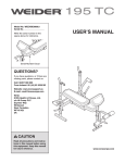
Model No. WEEVBE8909.0
Serial No.
Write the serial number in the
space above for reference.
USERʼS MANUAL
Serial Number Decal (under seat)
QUESTIONS?
If you have questions, or if there are
missing parts, please contact us:
Call: 08457 089 009
From Ireland: 00 (44) 53 9236102
Website: www.iconsupport.eu
E-mail: [email protected]
Write:
ICON Health & Fitness, Ltd.
c/o HI Group PLC
Express Way
Whitwood, West Yorkshire
WF10 5QJ
UK
CAUTION
Read all precautions and instructions in this manual before using
this equipment. Keep this manual
for future reference.
www.iconeurope.com
TABLE OF CONTENTS
WARNING DECAL PLACEMENT . . . . . . . . . . . . . . . . . . . . . . . . . . . . . . . . . . . . . . . . . . . . . . . . . . . . . . . . . . . . . .2
IMPORTANT PRECAUTIONS . . . . . . . . . . . . . . . . . . . . . . . . . . . . . . . . . . . . . . . . . . . . . . . . . . . . . . . . . . . . . . . . .3
BEFORE YOU BEGIN . . . . . . . . . . . . . . . . . . . . . . . . . . . . . . . . . . . . . . . . . . . . . . . . . . . . . . . . . . . . . . . . . . . . . . .4
PART IDENTIFICATION CHART . . . . . . . . . . . . . . . . . . . . . . . . . . . . . . . . . . . . . . . . . . . . . . . . . . . . . . . . . . . . . . .5
ASSEMBLY . . . . . . . . . . . . . . . . . . . . . . . . . . . . . . . . . . . . . . . . . . . . . . . . . . . . . . . . . . . . . . . . . . . . . . . . . . . . . . .6
ADJUSTMENT . . . . . . . . . . . . . . . . . . . . . . . . . . . . . . . . . . . . . . . . . . . . . . . . . . . . . . . . . . . . . . . . . . . . . . . . . . . .11
EXERCISE GUIDELINES . . . . . . . . . . . . . . . . . . . . . . . . . . . . . . . . . . . . . . . . . . . . . . . . . . . . . . . . . . . . . . . . . . .13
PART LIST . . . . . . . . . . . . . . . . . . . . . . . . . . . . . . . . . . . . . . . . . . . . . . . . . . . . . . . . . . . . . . . . . . . . . . . . . . . . . . .14
EXPLODED DRAWING . . . . . . . . . . . . . . . . . . . . . . . . . . . . . . . . . . . . . . . . . . . . . . . . . . . . . . . . . . . . . . . . . . . . .15
ORDERING REPLACEMENT PARTS . . . . . . . . . . . . . . . . . . . . . . . . . . . . . . . . . . . . . . . . . . . . . . . . . .Back Cover
WARNING DECAL PLACEMENT
This drawing shows the location(s) of the warning
decal(s). If a decal is missing or illegible, see
the front cover of this manual and request a
free replacement decal. Apply the decal in the
location shown. Note: The decal(s) may not be
shown at actual size.
WEIDER is a registered trademark of ICON IP, Inc.
2
IMPORTANT PRECAUTIONS
WARNING:
To reduce the risk of serious injury, read all important precautions and
instructions in this manual and all warnings on your weight bench before using your weight bench.
ICON assumes no responsibility for personal injury or property damage sustained by or through the
use of this product.
1. Before beginning any exercise program,
consult your physician. This is especially
important for persons over age 35 or persons with pre-existing health problems.
10. The weight bench is designed to support a
maximum user weight of 300 lbs. (136 kg)
and a maximum total weight of 510 lbs. (231
kg). Do not place more than 210 lbs. (95 kg),
including a barbell and weights, on the
weight rests. Do not place more than 70 lbs.
(32 kg) on the leg lever. Note: The weight
bench does not include a barbell or weights.
2. Read all instructions in this manual and all
warnings on the weight bench before using
the weight bench. Use the weight bench only
as described in this manual.
11. Before setting a barbell on the weight rests,
make sure that the weight rests are inserted
as far as possible and that they are turned to
the locked position.
3. It is the responsibility of the owner to ensure
that all users of the weight bench are adequately informed of all precautions.
4. The weight bench is intended for home use
only. Do not use the weight bench in a commercial, rental, or institutional setting.
12. Do not use a barbell that is longer than 6 ft.
(1.8 m) with the weight bench.
13. Always place equal amounts of weight on
both ends of the barbell when using it.
5. Keep the weight bench indoors, away from
moisture and dust. Place the weight bench
on a level surface, with a mat beneath it to
protect the floor or carpet. Make sure that
there is enough clearance around the weight
bench to mount, dismount, and use it.
14. When adding or removing weights, always
keep some weight on both ends of the barbell.
15. When using the leg lever, place a barbell
with the same amount of weight on the
weight rests to balance the bench.
6. Inspect and properly tighten all parts regularly. Replace any worn parts immediately.
7. Keep children under age 12 and pets away
from the weight bench at all times.
16. When using the backrest in a level position
or an inclined position, make sure that the
backrest support is inserted completely into
the uprights and that it is turned to the
locked position.
8. Keep hands and feet away from moving
parts.
9. Always wear athletic shoes for foot protection while exercising.
17. If you feel pain or dizziness while exercising,
stop immediately and cool down.
3
BEFORE YOU BEGIN
Thank you for selecting the new WEIDER® 190 TC
weight bench. The weight bench offers a selection of
exercises designed to develop the major muscle
groups of the upper body. Whether your goal is to tone
your body, build dramatic muscle size and strength, or
improve your cardiovascular system, the weight bench
will help you to achieve the specific results you want.
reading this manual, please see the front cover of this
manual. To help us assist you, note the product model
number and serial number before contacting us. The
model number and the location of the serial number
decal are shown on the front cover of this manual.
Before reading further, please look at the drawing
below and familiarize yourself with the parts that are
labeled.
For your benefit, read this manual carefully before
using the weight bench. If you have questions after
ASSEMBLED DIMENSIONS:
Height: 3 ft. 11 in. (119 cm)
Width: 2 ft. 6 in. (76 cm)
Depth: 5 ft. 2 in. (157 cm)
Weight Rest
Backrest Support
Upright
Backrest
Lock Knob
Seat
Lock Pin
Leg Lever
Weight Tube
4
PART IDENTIFICATION CHART
Refer to the drawings below to identify small parts used in assembly. The number in parentheses by each drawing is the key number of the part, from the PART LIST near the end of this manual. IMPORTANT: If you cannot
find a part in the hardware kit, check to see if it has been preassembled.
M10 Locknut (31)
M6 Washer (22)
M6 x 40mm Screw (32)
M10 Washer (30)
M10 x 19mm Screw (5)
M10 x 63mm Bolt (25)
M6 x 16mm
Screw (24)
M10 x 35mm Carriage Bolt (37)
M10 x 66mm Bolt (28)
M10 x 135mm Bolt (23)
5
ASSEMBLY
To make assembly easier, carefully read the
following information and instructions:
• The following tools (not included) may be required
for assembly:
two adjustable wrenches
• Assembly requires two persons.
one rubber mallet
• Because of its weight and size, the weight bench
should be assembled in the location where it will
be used. Make sure that there is enough clearance to walk around the weight bench as you
assemble it.
one standard screwdriver
one Phillips screwdriver
Assembly may be more convenient if you have a
socket set, a set of open-end or closed-end
wrenches, or a set of ratchet wrenches.
• Place all parts in a cleared area and remove the
packing materials. Do not dispose of the packing
materials until assembly is completed.
• For help identifying small parts, use the PART
IDENTIFICATION CHART on page 5.
1.
1
To make assembly easier, make sure
that you have read the assembly tips in
the box above.
Attach a Base (36) to an Upright (1) with two
M10 x 35mm Carriage Bolts (37) and two M10
Locknuts (31).
1
Attach the other Base (36) to the other
Upright (1) in the same way.
1
31
31
36
37
6
36
2. Orient one of the Uprights (1) so that the
Upright Cover (10) is on the side shown.
2
Next, orient a Left Joint Plate (35) and a Right
Joint Plate (11) as shown. Attach the Joint
Plates to the Upright (1) with two M10 x 66mm
Bolts (28) and two M10 Locknuts (31). Do not
tighten the Locknuts yet.
10
1
Repeat this step with the other Upright (1)
and the other Joint Plates (11, 35), making
sure that they are oriented as shown.
11
35
11
28
3. Attach one end of the Crossbar (2) to two Joint
Plates (11, 35) with two M10 x 66mm Bolts (28)
and two M10 Locknuts (31). Do not tighten the
Locknuts yet.
31
35
3
Attach the other end of the Crossbar (2) in
the same way.
35
28
7
11
31
2
1
4. Attach the Front Leg (4) to the Frame (3) with
an M10 x 19mm Screw (5), an M10 x 66mm
Bolt (28), an M10 Washer (30), and an M10
Locknut (31). Do not tighten the Screw or the
Locknut yet.
4
31
5. Apply some of the included grease to an M10 x
63mm Bolt (25).
3
5
30
4
28
5
Attach the Frame (3) to the upper set of holes
in the bracket on the Crossbar (2) with the M10
x 63mm Bolt (25) and an M10 Locknut (31). Do
not overtighten the Locknut; the Frame must
pivot easily.
27
3
Next, tighten the Lock Knob (27) into the bracket
on the Crossbar (2) and into the Frame (3).
31
2
Grease
See the inset drawing. Insert the Lock Pin (38)
into the lower set of holes in the bracket on the
Crossbar (2).
25
2
38
6. Insert the Backrest Support (14) into a set of
holes in the Uprights (1). Rotate the Backrest
Support so that the locking pin is wrapped
around the Upright (see the inset drawing).
6
14
Next, insert a Weight Rest (15) into an Upright
(1). Rotate the Weight Rest so that the locking
pin is wrapped around the Upright.
Locking
Pin
Attach the other Weight Rest (15) in the
same way. Make sure that the Weight Rests
are at the same height.
15
Locking
Pin
Locking
Pin
See steps 2–4. Tighten the M10 Locknuts
(31) and the M10 x 19mm Screw (5) used in
these steps.
8
1
15
1
7. Apply grease to an M10 x 60mm Bolt (25).
7
Attach the Leg Lever (6) to the Front Leg (4) with
the M10 x 63mm Bolt (25) and an M10 Locknut
(31). Do not overtighten the Locknut; the Leg
Lever must pivot easily.
6
31
4
25
Grease
8. Insert a Pad Tube (12) into the Leg Lever (6).
8
Slide two Foam Pads (13) onto the Pad Tube
(12), and then press two Pad Caps (34) into the
Pad Tube.
Attach the other Pad Tube (12), Foam Pads,
(13), and Pad Caps (34) in the same way.
34
13
6
34
12
13
12
9. Orient the Backrest (8) and the Backrest Tubes
(7) as shown.
9
Attach the Backrest Tubes (7) to the Backrest
(8) with four M6 x 40mm Screws (32) and four
M6 Washers (22). Do not tighten the Screws
yet.
34
13
34
8
Wide
End
22
7
Holes
32
9
13
22
32
10. Apply grease to an M10 x 135mm Bolt (23).
Attach the Backrest Tubes (7) to the welded
tube on the Frame (3) with the M10 x 135mm
Bolt (23), two M10 Washers (30), and an M10
Locknut (31). Do not overtighten the Locknut;
the Backrest Tubes must pivot easily.
10
31 30
See step 9. Tighten the M6 x 40mm Screws
(32).
11. Attach the Seat (9) to the Frame (3) with four
M6 x 16mm Screws (24).
3
7
Tube
11
30
Grease
23
9
3
24
12. Make sure that all parts are properly tightened before you use the weight bench. The use of all remaining parts will be explained in ADJUSTMENT, beginning on page 11.
10
ADJUSTMENT
The weight bench is designed to be used with your own weight set (not included). The steps below explain how
the weight bench can be adjusted. See EXERCISE GUIDELINES on page 13 for important exercise information,
and refer to the accompanying exercise guide to see the correct form for several exercises. Refer also to the
exercise information accompanying your weight set for additional exercises.
Make sure that all parts are properly tightened each time the weight bench is used. Replace any worn parts immediately. The weight bench can be cleaned with a damp cloth and a mild, non-abrasive detergent; do not use solvents to clean the weight bench.
ADJUSTING THE BACKREST
The Backrest (8) can be used in a declined position, a level position, or either of two inclined positions. To use the Backrest in the declined position,
remove the Backrest Support (14) and lay the
Backrest on the Crossbar (2).
To use the Backrest (8) in the level position or an
inclined position, lift the Backrest and insert the
Backrest Support (14) into one of the sets of holes
in the Uprights (1). Rotate the Backrest Support so
that the locking pin is wrapped around the Upright.
Locking
Pin
WARNING: When using the
1
14
8
1
2
Backrest (8) in a level position or an
inclined position, make sure that the
Backrest Support (14) is inserted completely into both Uprights (1) and that it is
turned to the locked position.
ATTACHING WEIGHTS TO THE LEG LEVER
To use the Leg Lever (6), slide the desired weights
(not included) onto the weight tube.
6
WARNING:
Do not place more
than 70 lbs. (32 kg) on the Leg Lever (6).
Weight
Tube
Weight
11
ADJUSTING THE WEIGHT RESTS
To change the height of the Weight Rests (15),
remove them from the Uprights (1) and insert them
into a different set of holes in the Uprights. Rotate
the Weight Rests so that the locking pins are
wrapped around the Uprights.
Locking
Pin
15
1
WARNING:
Locking
Pin
15
Always rotate the
Weight Rests (15) so that the locking pins
are wrapped around the Uprights (1).
Always set both Weight Rests at the same
height.
1
STORING THE WEIGHT BENCH
Before storing the weight bench, remove any
weights from the Leg Lever (6).
To store the weight bench, first remove the Lock
Knob (27) and the Lock Pin (38) from the bracket
on the Crossbar (2).
6
4
Next, raise the Frame (3) and the Front Leg (4) to
the position shown.
Then, insert the Lock Pin (38) into the side of the
bracket on the Crossbar (2), and insert the Lock
Knob (27) into the top of the bracket. The Lock Pin
will prevent the weight bench from unfolding.
3
27
38
12
2
EXERCISE GUIDELINES
FOUR TYPES OF STRENGTH WORKOUTS
Note: A “repetition” is one complete cycle of an exercise, such as one sit-up. A “set” is a series of repetitions.
Warming Up—Start with 5 to 10 minutes of stretching
and light exercise. A warm-up increases your body
temperature, heart rate, and circulation in preparation
for exercise.
Muscle Building—Work your muscles near their maximum capacity and progressively increase the intensity
of your exercise. Adjust the intensity level of an individual exercise as follows:
• Change the amount of resistance used.
• Change the number of repetitions or sets performed.
Use your own judgment to determine the amount of
resistance that is right for you. Begin with 3 sets of 8
repetitions for each exercise you perform. Rest for 3
minutes after each set. When you can complete 3 sets
of 12 repetitions without difficulty, increase the amount
of resistance.
Toning—Tone your muscles by working them to a
moderate percentage of their capacity. Select a moderate amount of resistance and increase the number
of repetitions in each set. Complete as many sets of
15 to 20 repetitions as possible without discomfort.
Rest for 1 minute after each set. Work your muscles
by completing more sets rather than by using high
amounts of resistance.
Weight Loss—To lose weight, use a low amount of
resistance and increase the number of repetitions in
each set. Exercise for 20 to 30 minutes, resting for a
maximum of 30 seconds between sets.
Cross Training—Combine strength training and aerobic exercise by following this type of program:
• Strength workouts on Monday, Wednesday, and
Friday.
• 20 to 30 minutes of aerobic exercise on Tuesday
and Thursday.
• One full day of rest each week to give your body
time to regenerate.
Working Out—Include 6 to 10 different exercises in
each workout. Select exercises for every major muscle
group, emphasizing areas that you want to develop. To
give balance and variety to your workouts, vary the
exercises from workout to workout.
Cooling Down—Finish with 5 to 10 minutes of
stretching. Stretching increases the flexibility of your
muscles and helps to prevent post-exercise problems.
EXERCISE FORM
Move through the full range of motion for each exercise and move only the appropriate parts of the body.
Perform the repetitions in each set smoothly and without pausing. The exertion stage of each repetition
should last about half as long as the return stage.
Exhale during the exertion stage of each repetition and
inhale during the return stroke. Never hold your
breath.
Rest for a short period of time after each set:
• Muscle Building—Rest for three minutes after each
set.
• Toning—Rest for one minute after each set.
• Weight Loss—Rest for 30 seconds after each set.
STAYING MOTIVATED
For motivation, keep a record of each workout. Write
the date, the exercises performed, the resistance
used, and the numbers of sets and repetitions completed. Record your weight and key body measurements once a month. To achieve good results, make
exercise a regular and enjoyable part of your life.
WORKOUT GUIDELINES
Familiarize yourself with the equipment and learn the
proper form for each exercise. Use your own judgment
to determine the appropriate length of time for each
workout, and the numbers of repetitions and sets to
complete. Progress at your own pace and be sensitive
to your bodyʼs signals. Follow each strength workout
with at least one day of rest.
13
PART LIST—Model No. WEEVBE8909.0
Key No. Qty.
1
2
3
4
5
6
7
8
9
10
11
12
13
14
15
16
17
18
19
20
21
2
1
1
1
1
1
2
1
1
2
2
2
4
1
2
3
1
2
4
2
2
Description
Key No.
Upright
Crossbar
Frame
Front Leg
M10 x 19mm Screw
Leg Lever
Backrest Tube
Backrest
Seat
Upright Cover
Right Joint Plate
Pad Tube
Foam Pad
Backrest Support
Weight Rest
50mm Square Inner Cap
25mm Round Angled Cap
38mm Square Inner Cap
25mm Square Inner Cap
25mm Round Inner Cap
21mm Round Inner Cap
22
23
24
25
26
27
28
29
30
31
32
33
34
35
36
37
38
*
*
*
Qty.
4
1
4
2
6
1
9
6
3
16
4
1
4
2
2
4
1
–
–
–
Description
R0709A
M6 Washer
M10 x 135mm Bolt
M6 x 16mm Screw
M10 x 63mm Bolt
25mm x 50mm Inner Cap
Lock Knob
M10 x 66mm Bolt
M4 x 16mm Screw
M10 Washer
M10 Locknut
M6 x 40mm Screw
25mm Round Thick Inner Cap
Pad Cap
Left Joint Plate
Base
M10 x 35mm Carriage Bolt
Lock Pin
Userʼs Manual
Exercise Guide
Grease Packet
Note: Specifications are subject to change without notice. For information about ordering replacement parts, see
the back cover of this manual. *These parts are not illustrated.
14
EXPLODED DRAWING—Model No. WEEVBE8909.0
16
29
15
8
10
20
19
21
29
14
31 30
1
31
31
35
37
9
31 11
26
36
26
5
38
13
24
34
21
17
18
15
32
23
29
16
10
20
29
16
31 30
1
4
12
13
12
13
15
7
31
35
31
26
22
32
11
28
6
33
30
22
31
27
7
25
18
13
19
2
31
28
3
28
R0709A
25
26
31
31
36
26
34
37
26
ORDERING REPLACEMENT PARTS
To order replacement parts, please see the front cover of this manual. To help us assist you, be prepared to
provide the following information when contacting us:
• the model number and serial number of the product (see the front cover of this manual)
• the name of the product (see the front cover of this manual)
• the key number and description of the replacement part(s) (see the PART LIST and the EXPLODED
DRAWING near the end of this manual)
Part No. 279716 R0709A
Printed in China © 2009 ICON IP, Inc.