1
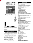
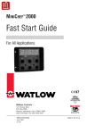
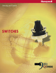
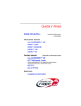
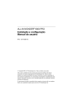
Series 142
User’s Manual
General Description
The Watlow Series 142 Safety Limit is a compact,
environmentally protected safety limit or temperature
controller. The limit has a single thermocouple input and
is available in several common ranges.
The Series 142 Safety Limit has a single mechanical
relay output, and operates as a high limit, latching control
with manual and/or auto-power reset. Fixed set points are
available.
The Series 142 Safety Limit controller is ideally
suited for limit applications requiring tamper-proof operation, agency approvals and immunity to hostile environments.
• The factory-fixed set point cannot be altered by operator
action or neglect.
• Agency approvals ensure compliance with recognized
standards.
• Epoxy potting makes the Series 142 resistant to environments with vibration or humid/corrosive conditions.
Safety High Limit or
On-Off Heat Controller
Compact size and sub-panel mounting make the
Series 142 readily adaptable to many applications. Its
single, factory-fixed set point thermocouple input and
Form C, 3 amp electromechanical relay output provides
simplicity and reliability for many applications. Sensor
break protection ensures fail-safe process shut down upon
input failure.
Safety Information
We use note, caution and warning symbols throughout this manual to draw your attention to important operational and safety information.
TOTAL
CUSTOMER
SATISFACTION
A “NOTE” marks a short message to alert you to an
important detail.
3 Year Warranty
A “CAUTION” safety alert appears with information
that is important for protecting your equipment and performance. Be especially careful to read and follow all
cautions that apply to your application.
A “WARNING” safety alert appears with information
that is important for protecting you, others and equipment
from damage. Pay very close attention to all warnings that
apply to your application.
The safety alert symbol, ç, (an exclamation point in
a triangle) precedes a general CAUTION or WARNING
statement.
1241 Bundy Boulevard, P.O. Box 5580, Winona, Minnesota USA 55987-5580
Phone: +1 (507) 454-5300, Fax: +1 (507) 452-4507,
Internet: http://www.watlow.com
0600-0023-0000 Rev E
March 2002
Supersedes
0600-0023-0000 Rev D
$5.00
Made in the U.S.A.
The electrical hazard symbol, Ó, (a lightning bolt in a
triangle) precedes an electric shock hazard CAUTION or
WARNING safety statement.
Units With Remote Setpot Assembly
Installation
35mm
(1.38 in.)
70mm
(2.76 in.)
1. Drill two 51mm (2.0 in.) diameter holes in the desired
remote setpot assembly location. See Figure 2b.
35mm
(1.38 in.)
29mm.
(1.13 in)
2. Using the dial scale as a location template, center and
mark all four mounting holes on the dial scale with a
center punch.
3. For bolted dial scale assembly, drill four 3mm (0.125 in.)
diameter clearance holes. If you are using a screw
assembly, use a tap drill. Tap drill sizes used are:
103mm
(4.05 in.)
Tap Drill Size
#44 - 2mm dia. (0.086 in.)
#43 - 2mm dia. (0.089 in.)
#42 - 2mm dia. (0.093 in.)
89mm
(3.50 in.)
Screw/Thread Size
#4.36
#4.40
#4.48
4. Drill four 5mm (0.189 in.) diameter holes in desired
panel location. See Figure 2b.
5. Mount the Series 142 with four screws.
Use a 6mm (0.25 in.) hex nut
for proper clearance.
Two 5mm (0.187 in.) dia.
mounting holes
Figure 2a — Series 142 dimensions.
6. Connect sensor, load and remote setpot assembly per
Wiring Diagram. See the wiring pages.
4 mounting holes
Mechanical Zero
Installation Procedure
1. Drill two 5mm (0.187 in.) diameter holes in the desired
panel location.
2. Mount the unit with two 6-32 screws, 6mm (0.25 in.) hex
nut and #6 internal tooth lock washer.
3. Use the correct thermocouple type per the model number on the unit sticker. See the side of the case.
• Use correct thermocouple polarity. Red is negative.
• Insulate the thermocouple mounting from the mounting surface to prevent heat migration input errors.
• Thermocouple leads should be twisted pair wire and
routed separately from any other lines.
• In electrically-noisy environments (heavy switching
contactors, motors, solenoids, etc.), use shielded thermocouple lead wire with the shield connected at the
sensor end only.
• Use a separate thermocouple to maintain the limit
function of this controller; do not parallel thermocouple input from the primary
controller.
4. All wiring and fusing must conform to the National
Electric Code (NEC) NFPA70 and any other locally
applicable codes.
5. Fuse the independent load voltage on the L1 (hot) side
and connect it to the common (C) side of the relay.
13mm
(0.53 in.)
68mm
(2.69 in. sq.)
76mm
(3.00 in. sq.)
23mm
(0.9 in.)
43mm.
(1.72 in)
Figure 2b — Setpot dimensions and mechanical zero
location.
Dial Scale Alignment to Mechanical Zero
1. Turn the dial scale knob completely counterclockwise (to
mechanical zero).
2. If the “Indicator” line on the setpot knob skirt, and
“Mechanical Zero” (represented by a small line beyond
the low end of the scale) are not aligned, loosen both set
screws on the setpot knob, and rotate the knob until
both lines meet.
3. Tighten both set screws.
NOTE: For applications where the CE mark is required, all quick
connect and spade terminals must be pre-insulated to meet IEC
730 specifications.
2 ■ User’s Manual
Watlow Series 142
Wiring
P3
Thermocouple +
NOTE: All terminals are 4mm (1/4 in.) quick connects.
P2
Thermocouple P1
P3
Thermocouple +
Reset
P2
Thermocouple -
Temperature
Control Output
P1
External
Load
L2
N.O.
L2
Reset
N.O.
L2
Neutral
120V~
N.C.
COM
L1
L1
COM
N.C.
L1
Fuse
Fuse
Hot
Figure 3d — 3A mechanical relay wiring.
P3
Figure 3a — 120V~ power wiring (142A - _ _ _ _ - 1 _ 00).
Thermocouple +
P2
Thermocouple -
Red
P1
P3
Thermocouple +
P2
Reset
Thermocouple P1
N.O.
L2
Reset
L2
N.C.
L1
Fuses
208/240V~
COM
N.O.
COM
L1
N.C.
Figure 3e — Thermocouple wiring.
NOTE: Extension wire for thermocouples must be of the same alloy
as the thermocouple itself to limit errors.
Figure 3b — 208/240V~ power wiring
(142A - _ _ _ _ - 2 _ 00).
Remote Setpot
Green
P3
Thermocouple +
Black
P3
Thermocouple +
Red
P2
Thermocouple P1
P2
Thermocouple P1
Customer Supplied
N.O. Momentary Switch
Reset
Reset
N.O.
L1
COM
N.C.
L1
N.C.
COM
L2
N.O.
L2
Figure 3f — Remote setpot (142A - 2 _ _ _ - _ _ 00).
Figure 3c — Reset switch.
NOTE: Jumpering the reset terminals does not convert from limit
to an on-off control mode.
Watlow Series 142
User’s Manual ■ 3
System Wiring Example
L2
L1
Control
Power
Fuse
21
22
Earth
Ground
11
12
N.O.
13
COM
L1
Load
Power Fuses
(+) 9
Indicator
turns on
when limit trips
10
(-) 988A-2BA0-0000
Rear View
N.C. N.O.
COM
Series 142
142A - 3 _ _ _ - 1200
Safety Limit Control
High Limit
Mechanical
Contactor
L2
Load
Power
N.O.
Heat
Load
Limit
Power
Process
Sensor
L1
L2
Thermocouple
- +
Fuse
Momentary Switch
Manual Reset for Limit Control
Limit Sensor
Figure 4 — System wiring example.
∫
WARNING:
Install high or low temperature limit control protection in systems where an overtemperature fault condition could present a
fire hazard or other hazard. Failure to install temperature limit
control protection where a potential hazard exists could result
in damage to equipment and property, and injury or death to
personnel.
ç
CAUTION:
Watlow mercury relay loads must have a unity power factor.
For RESISTIVE LOADS ONLY.
4 ■ User’s Manual
Watlow Series 142
Specifications
(2072)
Limit Control Mode
• High limit control
• Latched manual reset with ±1.7°C (3°F) hysteresis
• Can only be reset when process temperature drops below limit
set point. Terminals are provided for remote reset in the event of
an overtemperature condition. (Reset switch supplied by user.)
On-off Temperature Control Mode
• Off — when process temperature exceeds factory-fixed or remote
adjustable set point
• On — when process temperature is less than factory-fixed or
remote adjustable set point
• Hysteresis (switching differential) ±1.7°C (3°F) nominal
Agency Approvals
•
and
, File #E43684
197 Commercial Cooking Appliances
873 Temperature Indicating and Regulating Equipment
991 Test for Safety Related Controls Employing Solid State
Devices
®
•
#C3236001 approved, Gas Appliance Thermostat, ANSI
Z21.23
• CE 89/336/EEC Electromagnetic Compatibility Directive
EN61326, Immunity, Class B Emissions
• CE 73/23/EEC Low Voltage Directive
EN60730-1, EN60730-2-9, Safety
Operator Interface
• Non-adjustable, factory-fixed or remote adjustable set point
Remote Set Point
• Dial scale calibrated to compensate for sensor non-linearity
• Dual °F/°C scales
Accuracy
Adjustable Set Point
• Calibration accuracy: ±1% of span, at 25°C ±3°C (77°F ±5°F)
ambient and rated line voltage ±1%
• Set point accuracy: ±3% of dial scale
• Accuracy span: 540°C (1000°F) minimum
Fixed Set Point
• Calibration accuracy: ±6°C±/10°F of setting, at 25°C ±3°C (77°F
±5°F) ambient and rated line voltage ±1%
Thermocouple Stability
• Thermocouple: Typically 9µV/°C ambient (±5µV/°F ambient) input
referenced
• RTD: Typically 0.2°C/°C ambient (0.2°F/°F ambient)
Voltage Stability
• ±0.01% of span (min span of 540°C or 1000°F) per % of rated
line voltage
Thermocouple Input
• Grounded or ungrounded Type E, J, K or T. Sensor break
protection de-energizes output.
• Factory-set, thermocouple ranges
US
Watlow Series 142
Output
• Electromechanical relay1, SPDT, 3A @ 120/240V~ or 3A @
30VÎ (dc), Form C, with RC suppression on on-off temperature
controller version. Off-state output impedance is 20kΩ with RC
suppression.
Output Relay Status Upon Power Restoration
(Assuming process temperature is not above set point.)
• Auto reset: Output relay automatically re-energizes
• Manual reset: Manual reset is required to re-energize output relay
Line Voltage/Power
• 120V~, ±10%; (108-132V~), 50/60Hz, ±5%
• 208/240V~, ±10%; (187-264V~), 50/60Hz, ±5%
• Power consumption 4VA maximum
Operating Environment
• 0 to 65°C (32 to 149°F)
• 0 to 90% RH, non-condensing
Storage Temperature
• -40 to 85°C (-40 to 185°F)
Terminals
• 1⁄4 inch quick connect lugs (spade/ appliance)
Dimensions
•
•
•
•
•
Controller
Length
102mm
Width
70mm
Height
103mm
Controller Weight
0.36kg
Shipping Weight
0.57kg
Set Point Assembly
Dial Scale
76mm
Pot Depth Behind
25mm
Knob Depth in Front
31mm
Lead Length
610mm
Weight
0.09kg
(4 in.)
(2.8 in.)
(4.05 in.)
(0.79 lb.)
(1.25 lbs.)
•
(3 in. sq.)
•
(1.0 in.)
•
(1.2 in.)
•
(24 in.)
•
(0.2 lb.)
1Electromechanical relays are warranted for 100,000 closures
only.
UL® is a registered trademark of Underwriter’s Laboratories, Inc.
Note: Specifications subject to change without notice.
User’s Manual ■ 5
Ordering Information
(2071)
To order, complete the code number
142A-____-__00
to the right with the information below:
Series 142 = Temperature safety limit,
limit, latching 3A relay, environmentally sealed
controller, or basic on-off temperature controller
Output Type
A = Electromechanical relay1, Form C, 3A, with RC
suppression on on-off temperature controller, without
contact suppression on limit controller
Set Point
2 = Remote/Adjustable2
3 = Fixed (See below for available factory-fixed set points)
Input (Thermocouple)
ANSI Type E
669 =
685 =
670 =
668 =
110°C
129°C
150°C
155°C
(230°F)
(265°F)
(302°F)
(311°F)
679 =
684 =
675 =
678 =
185°C
232°C
260°C
296°C
(365°F)
(450°F)
(500°F)
(565°F)
682 =
664 =
302°C
(575°F)
566°C (1050°F)
0 to 315°C
(32 to 600°F)
10°C
(50°F)
16°C
(61°F)
46°C (115°F)
63°C (145°F)
65°C (149°F)
68°C (155°F)
79°C (175°F)
85°C (185°F)
93°C (200°F)
102°C (215°F)
107°C (225°F)
110°C (230°F)
121°C (250°F)
129°C (265°F)
6033 =
6043 =
6053 =
6063 =
707 =
6073 =
6083 =
6993 =
689 =
704 =
6983 =
6123 =
6133 =
614 =
615 =
616 =
275°F
300°F
325°F
350°F
360°F
375°F
400°F
425°F
444°F
465°F
450°F
475°F
500°F
525°F
550°F
575°F
(135°C)
(149°C)
(163°C)
(177°C)
(182°C)
(191°C)
(204°C)
218°C()
(229°C)
(240°C)
(232°C)
(246°C)
(260°C)
(274°C)
(288°C)
(302°C)
617 =
618 =
693 =
620 =
621 =
622 =
623 =
624 =
625 =
627 =
628 =
696 =
630 =
631 =
632 =
633 =
316°C (600°F)
329°C (625°F)
343°C (650°F)
357°C (675°F)
371°C (700°F)
385°C (725°F)
399°C (750°F)
413°C (775°F)
427°C (800°F)
454°C (850°F)
468°C (875°F)
482°C (900°F)
496°C (925°F)
510°C (950°F)
524°C (975°F)
538°C (1000°F)
673 =
637 =
638 =
639 =
640 =
687 =
717 =
641 =
642 =
643 =
644 =
645 =
646 =
647 =
648 =
648°C
649°C
677°C
704°C
732°C
750°C
399°C
760°C
788°C
816°C
843°C
871°C
899°C
927°C
954°C
(1198°F)
(1200°F)
(1250°F)
(1300°F)
(1350°F)
(1382°F)
(750°F)
(1400°F)
(1450°F)
(1500°F)
(1550°F)
(1600°F)
(1650°F)
(1700°F)
(1750°F)
649 =
650 =
651 =
652 =
692 =
654 =
655 =
656 =
657 =
658 =
659 =
660 =
6614 =
6624 =
6634 =
ANSI Type J
706 =
626 =
718 =
653 =
666 =
686 =
6093 =
681 =
672 =
6003 =
688 =
6013 =
719 =
6023 =
715 =
ANSI Type K
716 =
711 =
125 =
619 =
667 =
671 =
695 =
690 =
674 =
677 =
629 =
691 =
634 =
635 =
636 =
50°C (122°F)
52°C (125°F)
125°C (257°F)
149°C (300°F)
238°C (460°F)
288°C (550°F)
300°C (572°F)
315°C (600°F)
700°C (700°F)
420°C (788°F)
427°C (800°F)
468°C (875°F)
565°C (1050°F)
593°C (1100°F)
621°C (1150°F)
982°C
1010°C
1038°C
1066°C
1093°C
1121°C
1149°C
1177°C
1204°C
1232°C
1260°C
1288°C
1316°C
1343°C
1371°C
(1800°F)
(1850°F)
(1900°F)
(1950°F)
(2000°F)
(2050°F)
(2100°F)
(2150°F)
(2200°F)
(2250°F)
(2300°F)
(2350°F)
(2400°F)
(2450°F)
(2500°F)
ANSI Type T
708 = -20°C
(-4°F)
705 = -200 to 350°C (-328 to 662°F)
680 =
16°C
(60°F)
714 =
79°C (175°F)
694 =
712 =
713 =
710 =
135°C
175°C
200°C
250°C
(275°F)
(347°F)
(392°F)
(482°F)
Line Voltage/Power
1 = 120V~
2 = 208/240V~
Control Operation
2 = High Limit Control—Manual reset on power loss and overtemperature
3 = High Limit Control—Auto reset on power loss/manual reset on
overtemperature
4 = Temperature Control—on-off heat
6 ■ User’s Manual
1 Electromechanical relays warranted for 100,000 closures
only.
2 User selectable range. Consult
factory for details. Setpot
required, sold separately.
3 CSAUS Gas Appliance
Thermostat approved.
4 Not within calibration tolerance range per ANSI circular
MC96.1.
Note: User documentation may
be available in French, German,
Spanish, Italian, and Dutch, as
well as English. Check Watlow’s
website (www.watlow.com/) for
availability. Specify language at
time of order.
Watlow Series 142
Declaration of Conformity
Series 142
WATLOW Winona, Inc.
1241 Bundy Boulevard
Winona, Minnesota 55987 USA
Declares that the following product:
English
Designation:
Series 142
Model Numbers:
142A – (2 or 3)(600 to 999) – (1 or 2)(1, 2, 3 or 4)
(any two letters or numbers.)
Classification:
Temperature Limit Control, Installation Category II,
Pollution degree II
Rated Voltage:
120 or 208/240 V~ (ac)
Rated Frequency:
50 or 60 Hz
Rated Power Consumption: 6 VA maximum
Meets the essential requirements of the following European Union Directives by using
the relevant standards show below to indicate compliance.
89/336/EEC Electromagnetic Compatibility Directive
EN 61326:1997 With A1:1998 – Electrical equipment for measurement, control and
laboratory use – EMC requirements (Industrial Immunity, Class A Emissions).
EN 61000-4-2:1996 With A1, 1998 – Electrostatic Discharge Immunity
EN 61000-4-3:1997 – Radiated Field Immunity
EN 61000-4-4:1995 – Electrical Fast-Transient / Burst Immunity
EN 61000-4-5:1995 With A1, 1996 – Surge Immunity
EN 61000-4-6:1996 – Conducted Immunity
EN 61000-4-11:1994 Voltage Dips, Short Interruptions and Voltage Variations Immunity
EN 61000-3-2:1995 With A1-3:1999 – Harmonic Current Emissions
EN 61000-3-3:1995 With A1:1998 – Voltage Fluctuations and Flicker
Erklärt, dass das folgende Produkt:
Deutsch
Bezeichnung:
Serie 142
Modell-Nummern:
142A – (2 oder 3)(600 bis 999) – (1 oder 2)(1, 2, 3
oder 4) - (Beliebige zwei Ziffern oder Buchstaben)
Klassifikation:
Temperaturregler, Installationskategorie II,
Verschmutzungsgrad 2
Nennspannung:
120 oder 208/240 V~ (ac)
Nennfrequenz:
50 oder 60 Hz
Nennstromverbrauch:
Max. 6 VA
Erfüllt die wichtigsten Normen der folgenden Anweisung(en) der Europäischen Union
unter Verwendung des wichtigsten Abschnitts bzw. der wichtigsten Abschnitte die
unten zur Befolgung aufgezeigt werden.
89/336/EEC Elektromagnetische Kompatibilitätsrichtlinie
EN 61326:1997 mit A1:1998 – Elektrisches Gerät für Messung, Kontrolle und
Laborgebrauch – EMV-Anforderungen (Störfestigkeit Industriebereich, Klasse
A Emissionen)
EN 61000-4-2:1996 mit A1, 1998 – Störfestigkeit gegen elektronische Entladung
EN 61000-4-3:1997 – Störfestigkeit gegen Strahlungsfelder
EN 61000-4-4:1995 – Störfestigkeit gegen schnelle Stöße/Burst
EN 61000-4-5:1995 mit A1, 1996 – Störfestigkeit gegen Überspannung
EN 61000-4-6:1996 – Geleitete Störfestigkeit
EN 61000-4-11:1994 Störfestigkeit gegen Spannungsabfall, kurze
Unterbrechungen und Spannungsschwankungen
EN 61000-3-2:1995 mit A1-3:1999 – Harmonische Stromemissionen
EN 61000-3-3:1995 mit A1:1998 – Spannungsfluktationen und Flimmern
EN 61000-3-3: 1995 Grenzen der Spannungsschwankungen und Flimmern
73/23/EEC Niederspannungsrichtlinie
EN 60730-1: 1993 Automatische elektrische Regelsysteme für de Haushalt
und ähnlichen Einsatz, Teil 1: Allgemeine Richtlinien
EN 60730-2-9: 1995 Automatische elektrische Regelsysteme für den Haushaltund ähnlichen Einsatz, Teil 2: Spezifische Richtlinien Abschnitt 2.9, Temperaturregelsysteme
73/23/EEC Low-Voltage Directive
EN 60730-1: 1993 Automatic electrical controls for household and similar
use, Part 1: General requirements:
EN 60730-2-9: 1995 Automatic electrical controls for household and similar use, Part
2; Particular requirements Section 2.9 Temperature sensing controls
Français
Séries 142
142A – (2 ou 3)(600 à 999) – (1 ou 2)(1, 2, 3 ou 4)
(N’importe quelle combinaison de deux lettres ou
chiffres)
Classification :
Régulation de température, Catégorie d’installation
II, Degré de pollution 2
Tension nominale :
120 ou 208/240 V~ (c.a)
Fréquence nominale :
50 ou 60 Hz
Consommation d’alimentation nominale : 6 VA maximum
déclare que le produit suivant :
Désignation :
Numéros de modèles :
Répond aux normes essentielles des directives suivantes de l'Union européenne en
utilisant les standards normalisés ci-dessous qui expliquent les normes auxquelles
répondre :
Directive 89/336/CEE sur la compatibilité électromagnétique
EN 61326:1997 avec A1 :1998 – Matériel électrique destiné à l’étalonnage, au
contrôle et à l’utilisation en laboratoire – Exigences CEM (Immunité industrielle, Émissions de catégorie A).
EN 61000-4-2:1996 Avec A1, 1998 – Immunité aux décharges électrostatiques
EN 61000-4-3:1997 – Immunité aux champs de radiation
EN 61000-4-4:1995 – Immunité contre les surtensions électriques rapides/ Rafale
EN 61000-4-5:1995 avec A1, 1996 – Immunité contre les surtensions
EN 61000-4-6:1996 – Immunité conduite
EN 61000-4-11:1994 Immunité contre les écarts de tension, interruptions courtes
et variations de tension
EN 61000-3-2:1995 avec A1-3 :1999 – Emissions de courant harmoniques
EN 61000-3-3:1995 avec A1 :1998 – Fluctuations et vacillements de tension
Directive 73/23/CEE sur les basses tensions
Declara que el producto siguiente:
Español
Designación:
Serie 142
Números de modelo:
142A – (2 o 3)(600 a 999) – (1 o 2)(1, 2, 3 o 4) (Cualesquiera dos letras o números)
Clasificación:
Control de temperatura, Categoría de instalación II,
Grado de contaminación 2
Tensión nominal:
120 o 208/240 V~ (CA)
Frecuencia nominal:
50 o 60 Hz
Consumo nominal de energía: 6 VA máximo
Cumple con los requisitos esenciales de las siguientes Directrices de la Unión
Europea mediante el uso de las normas aplicables que se muestran a continuación
para indicar su conformidad.
89/336/EEC Directriz de compatibilidad electromagnética
EN 61326:1997 CON A1:1998.– Equipo eléctrico para medición, control y uso
en laboratorio – Requisitos EMC (Inmunidad industrial, Emisiones Clase A).
EN 61000-4-2:1996 con A1, 1988 – Inmunidad a descarga electrostática
EN 61000-4-3:1997 – Inmunidad a campo radiado
EN 61000-4-4:1995 – Inmunidad a incremento repentino/rápidas fluctuaciones
eléctricas transitorias
EN 61000-4-5:1995 con A1, 1996 – Inmunidad a picos de voltaje o corriente
EN 61000-4-6:1996 – Inmunidad por conducción
EN 61000-4-11:1994 Inmunidad a caídas de voltaje, variaciones y pequeñas
interrupciones de voltaje
EN 61000-3-2:1995 con A1-3:1999 – Emisiones de corriente armónica
EN 61000-3-3:1995 con A1:1998 – Fluctuaciones de voltaje y centelleo.
73/23/EEC Directiva de Baja Tensión
EN 60730-1: 1993 Controles eléctricos automáticos para electrodomésticos y
aparatos de uso similar, Parte 1: Requerimientos generales
EN 60730-2-9: 1995 Controles eléctricos automáticos para electrodomésticos y
aparatos de uso similar, Parte 2: Requerimientos particulares Sección 2.9, Controles
para detección de temperatura
EN 60730-1 : 1993 Commandes électriques automatiques à usage domestique et similaire, Partie 1: Exigences générales
EN 60730-2-9 : 1995 Commandes électriques automatiques à usage domestique
et similaire, Partie 2: Exigences particulières, Section 2.9 Commandes de détection de la température
Jim Boigenzahn
Name of Authorized Representative
Winona, Minnesota, USA
Place of Issue
General Manager
Title of Authorized Representative
December 2001
Date of Issue
(2210)
Signature of Authorized Representative
Watlow Series 142
User’s Manual ■ 7
Glossary
Returns
automatic power reset — A feature in latching limit
controllers that does not recognize power outage as a limit
condition. When power is restored, the output is re-energized automatically, as long as the temperature is within
limits.
• Call or fax Customer Service for a Return Material
Authorization (RMA) number before returning a controller.
• Put the RMA number on the shipping label, and also on
a description of the problem.
• 20% of net price restocking charge applies to all standard units returned to stock.
electrical noise immunity — Ability of a temperature
control to operate normally in the presence of electrical
noise interference.
fixed set point — Temperature set point is preset at the
factory. It cannot be readjusted in the field.
latched output — Limit control output latches in deenergized condition when overtemperature condition
occurs and cannot be reset unless temperature drops
below set point.
limit or limit controller — A highly reliable, discrete
safety device (redundant to the primary controller) that
monitors and limits the temperature of the process or a
point in the process. When temperature exceeds or falls
below the limit set point, the limit controller interrupts
power through the load circuit. A limit controller can protect equipment and people when it is correctly installed
with its own power supply, power lines, switch and sensor.
manual reset — A feature on a limit controller that
requires human intervention to return the limit to normal
operation after a limit condition has occurred.
safety limit — An automatic limit intended for use in
applications where an over-temperature fault may cause a
fire.
Technical Assistance
If you encounter a problem with your Watlow controller, review all of your configuration information to verify
that your selections are consistent with your application:
inputs; outputs; alarms; limits; etc. If the problem persists
after checking the above, you can get technical support by
dialing +1 (507) 492-5300, 7 a.m. to 7 p.m. Central
Standard Time. An applications engineer will discuss your
application with you.
Please have the following information available
when calling:
• Complete model number
• Serial Number
• All configuration information • User’s Manual
Warranty
The Watlow Series 142 is warranted to be free of
defects in material and workmanship for 36 months after
delivery to the first purchaser for use, providing that the
units have not been misapplied. Since Watlow has no control over their use, and sometimes misuse, we cannot
guarantee against failure. Watlow's obligations hereunder, at Watlow's option, are limited to replacement, repair
or refund of purchase price, and parts which upon examination prove to be defective within the warranty period
specified. This warranty does not apply to damage resulting from transportation, alteration, misuse, or abuse.
Your Feedback
Your comments or suggestions on this manual are
welcome. Please send them to: Technical Writer, Watlow
Controls, 1241 Bundy Boulevard, P.O. Box 5580, Winona,
Minnesota 55987-5580; phone: +1 (507) 454-5300; fax: +1
(507) 452-4507. The Series 142 User’s Manual is copyrighted by Watlow Winona, Inc., © 2001, with all rights
reserved. (2209)
8 ■ User’s Manual
Watlow Series 142