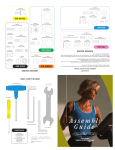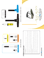
1
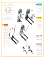
BLUE BAG
©2004 Vision Fitness. All Rights Reserved. 8.03 Part #Z92TM49-AG1812PRD
AG18.12PRD
REV3
Mar.03.04
• Elevation A/D or Elevation in % appears in the left window. PWM value or Speed appears in the right
window. "Cal Passed" will appear in the alphanumeric window when the Auto-Calibration is complete. The
treadmill will come to a complete stop and return to the start-up screen in the alphanumeric window.
• To begin Auto-Calibration, press START. The treadmill will run through minimum and maximum Speed and
maximum Elevation. This will take 3-5 minutes. Let the treadmill perform this complete function before exiting the
Engineering Mode.
• You need to access User Engineering Mode to run the Auto-Calibration. With the Safety Key in place, please
hold down SPEED DOWN and SELECT for 5 seconds. When in the User mode, "User Mode" appears in the
alphanumeric window. To access the data press the ELEVATION keys until "Auto-Cal" appears. Press Start to select
this function.
DO NOT STAND ON THE BELT WHEN PERFORMING THE AUTO-CALIBRATION
MODELS T9700HRT:
• Elevation A/D or Elevation in % appears in the left window. PWM value or Speed appears in the right
window. "End" will appear in the center window when the Auto-Calibration is complete. When Auto-Calibration
is complete, it will take the treadmill about 30 seconds to go to 0% Elevation and return to the start-up screen
with “P1” showing in the Function window.
• To begin Auto-Calibration, press START. The treadmill will run through minimum and maximum Speed and
maximum Elevation. This will take 3-5 minutes. Let the treadmill perform this complete function before exiting the
Engineering Mode.
• You need to access User Engineering Mode to run the Auto-Calibration. With the Safety Key in place, please
hold down SPEED DOWN and SELECT for 5 seconds. When in the User mode, "USEr" displays in the center
window. To access the data press the ELEVATION keys until "Auto" appears in the center window. Press Start to
select this function.
DO NOT STAND ON THE BELT WHEN PERFORMING THE AUTO-CALIBRATION
MODELS T9500HRT:
Once the treadmill is plugged in, you need to perform an Auto-Calibration to assure maximum performance.
AUTO CALIBRATION
HARDWARE INCLUDED
ORANGE BAG
M8 x 15L Bolts
Quantity: 4
4
Allen Wrench
Screwdriver
M8 x 20L Bolts
Quantity: 2
M8 x 55L Flathead Bolts
Quantity: 4
YELLOW BAG
M4 x 12L Panhead Screws
Quantity: 6
M8 x 135L Bolts
Quantity: 4
STEP
MM
8
PLATFORM TREADMILLS
T9500HRT AND T9700HRT
Assembly
Guide
TOOLS, HARDWARE, & PARTS INCLUDED
5mm L-Shaped Wrench
PARTS BOX
Water Bottle, Qty: 1
Heart Rate Chest Strap, Qty: 1
Color-coded Hardware Bags
Owner’s Guide
Assembly Guide
Warranty Card
Assembly
Guide
STEP
NOTE: Push all extra data cable into
the console mast. Make sure not to
pinch or cut the data cable.
STEP
STEP
• Mount the right-hand side mount
handlebar to the console mast using
two bolts (M8 x 135L). Repeat this on
the left-hand side.
3
2
Be sure to read your Owner’s Guide before using your new Platform Treadmill.
STEP
NOTE: It is recommended that you apply grease to the threads of each bolt as you assemble your Platform
3
Treadmill, to prevent loosening and noise. Also, during each assembly step, ensure that ALL nuts and bolts
are in place and partially threaded in before completely tightening any ONE bolt.
STEP
1
DATA CABLES
T9500HRT: Plug in the small data
cable into the small plug connection
on the lower control board. Plug in the
large data cable into the large plug
connection on the lower control
board.
T9700HRT: Plug the large 20ribbon cable into the 20-pin
connection on the lower control
board. Slide down the rubber covers
on the left & right console supports.
ORANGE BAG
• Slide the rubber covers on to the left
& right console supports, making sure
that the lower cutout is facing inward.
T9700HRT: Slide the data cable
down the right console support using
the white wire tie as a guide. Make
sure that the data (1 large ribbon
cable) goes through the large hole in
the lower part of the console upright.
BLUE BAG
• Mount the console to the console
mast using four bolts (M8 x 15L) and
tighten with the 5mm Allen wrench.
T9500HRT AND T9700HRT
PLATFORM TREADMILLS
To avoid possible damage to this Platform Treadmill, please follow these assembly steps in the correct
order. Before proceeding though, find your new Platform Treadmill’s serial number, located on the
underside of the main frame, and enter here:
2
STEP
• Install the motor cover making sure
that the rubber covers are inserted into
the motor cover. Secure the motor
cover using the six (M4 x 12L) screws
(see Yellow bag).
1
T9500HRT: Slide the data cables
down the right console support using
the white wire tie as a guide. Make
sure that the data cables (one small
grey
&
one
large
black
telephone-style cable) go through the
large hole in the lower part of the
console upright.
STEP
4
• Insert the left console support into
the console support bracket and
secure with two bolts (M8 x 55L
Flathead) in the side of the console
support bracket.
AUTO CALIBRATION
Please refer to back cover for this
procedure, then return to Step 5.
• Insert one bolt (M8 x 20L) in the
rear of the console support bracket.
• Tighten all three bolts with the bluehandled 5mm Allen wrench.
• Repeat this on the right side.
NOTE: There are no data cables on
the left side.
STEP
STEP
5
5
BELT TENSION
• If the running belt slips when used,
use the supplied 8MM Allen wrench to
turn the left and right tension bolts
clockwise 1/4-turn at a time until the
belt no longer slips.
• If the running belt is too far to the
right side, use the supplied 8MM Allen
wrench to turn the right tension bolt
clockwise 1/4-turn at a time until the
belt remains centered during use.
If the running belt is too far to the left
side, turn the left tension bolt
clockwise 1/4-turn at a time until the
belt remains centered during use.