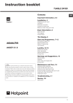
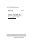
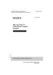
1
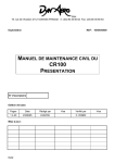
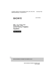
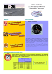
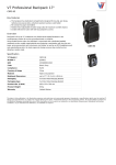
E4100
ASSEMBLY INSTRUCTIONS
To avoid possible damage to this Fitness Cycle,
please follow these assembly instructions.
Carefully remove all its parts from the box,
lay them out and review the parts list.
If any parts are missing, please call 1-800-335-4348, Ext 12
Before proceeding, find your Fitness Cycle’s serial number,
located on the underside of main frame, and enter here:
______________________________
Refer to this number when calling for service.
A41.2
IT
ALL
STARTS
WITH
A
VISION
E4100 Parts Diagram
E4100 Parts
VISION FITNESS E4100 Parts Description
Part #
Description
Count
Dimensions
Front Wheel Parts
#60
#61
#182
#183
Front Foot Wheel Axle
Front Transport Wheels
Outside Wheel Washers
Wheel Attachment Nuts
1
2
2
2
Arm Assembly Parts
#116
#115
#74
#105
#106
#169
#107
#183
Right Arm
Left Arm
Plastic Arm Cam Cover
Inside Cam Pulley
Outside Cam Pulley
Pulley Washer
Cam Pulley Spring
Cam Pulley Locknuts
1
1
2
2
2
4
2
2
Flat
Frame Parts
#62
#167
#65
#108
#82
#176
Rear Foot Assembly
Rear Foot Attach Bolts
Seat Post
Seat
Top Cap
Top Cap Screws
1
4
1
1
1
3
20mm L x 8mm D
Console Assembly Parts
#70
#78
#168
#95
#96
#179
#143
#163
Console Mast
Console Mast Plug
Console Mast Bolts
Console
RPM Sensor Wire
Upper Magnet Shift Cable
Lower Magnet Shift Cable
Console Attachment Bolts
1
1
2
1
1
1
1
6
Other Parts
#91
Pedals
2
38mm L x 8mm D
11mm L x 5mm D
E4100 Assembly
NOTE: During each assembly step, ensure that ALL nuts and bolts are in place and partially threaded in
before completely tightening any ONE bolt.
Step 1 • Rear Foot
1: Secure the Rear Foot Assembly (62) to the Frame by using the four Rear Foot Attachment Bolts (167).
Step 2 • Seat and Seat Post
1: Slide the Seat Post (65) into the frame seat post receiver tube. The seat post numbers should be
facing the right or seat pin side of the Fitness Cycle.
NOTE: Both nuts in the Seat Clamp should be tightened at the same time, to ensure a proper fit.
2: Attach the Seat (108) to the Seat Post (65) and tighten securely. To avoid scratching the seat post
paint, always hold the the seat pin knob out when adjusting the seat post height.
Step 3 • Console Mast
1: Remove the Top Cap Screws (176) which hold the Top Cap (82) to the frame. Then remove the Top
Cap (82).
NOTE: DO NOT thread in the Water Bottle Cage Bolts yet. Never slide the Top Cap (82) on or off with
the Waterbottle Cage Bolts threaded in, as they will scratch the paint on the Console Mast (70).
2: Slide the Top Cap (82) over the bottom of the Console Mast (70). The VISION decal on the Console
Mast (70) should be facing forward, away from the rider.
3: Locate the RPM Sensor Wire (96) and the Lower Magnet Shift Cable (143). Holding the Top Cap (82)
and Console Mast (70) above the frame console mast receiver tube, guide the RPM Sensor Wire (96)
and the Lower magnet Cable (143) through the Console Mast (70) while simultaneously sliding
the Console Mast (70) into the receiver tube.
4: Lift the Top Cap (82) up, install the two 38mm-long Console Mast Allen bolts (168) and tighten
securely.
5: Now slide the Top Cap (82) back into place. Make sure that the back end of the Top Cap (82) is
nested fully into the Seat Cap groove. Secure the Top Cap (82) by threading the three Top Cap Screws
back into their holes.
NOTE: Check that there are no large gaps between the Top Cap (82) and the Side Covers.
Step 4 • Console
1: Feed the Upper Magnet Shift Cable (179) into the topmost opening of the Console Mast (70).
2: Plug the RPM Sensor Wire (96) into the Console (95). DO NOT PINCH the RPM Sensor Wire (96)
between the Console (95) and the Console Mast (70). Make sure the cable fits in the slot cut in the
Console Mast Mount.
3: Mount the Console (95) to the Console Mast (70) using the six Console Attachment Phillip Head Bolts
(163).
E4100 Assembly
Step 5 • Connect Magnet Shift Cable
1: Turn the Tension Knob to position 8. Reach inside the opening
of the Console Mast (70) and connect the Upper Magnet Shift
Cable (179) to the rectangular red cable-slide on the end of the
Lower Magnet Shift Cable (143), as shown in the accompanying
illustrations.
2: While holding the metal separating tab (Figure 5), turn the
Tension Knob to Level 1 and then pull the tab out and discard.
3: Press the Console Mast Plug (78) into the opening of
the Console Mast (70).
Step 6 • Install Arms and Front Wheels
1: Tip the Fitness Cycle back until it is balanced on the Seat and
the back of the Rear Foot Support. Place cardboard beneath
the seat to avoid tearing or marring the seat cover.
2: Identify the Left and Right Arms (115 & 116). Insert the Front
Foot Wheel Axle (60) through the frame axle hole.
3: Remove the Cam Pulley Locknut (183), the two Pulley Spring
Washers (107), and the Outside Cam Pulley (106) from the Cam
Pulley Arm (75). Note the order and direction of these parts
before removal.
4: Place the bottom hole of the Right Arm (116) onto the Front
Foot Wheel Axle (60). Position the Right Arm (116) so that the
chromed slot rests against the inside Cam Pulley (105).
5: Place a thin layer of grease on the pulley surfaces. Reassemble
the parts removed in the above steps onto the Cam Pulley Arm
(75). Do not yet tighten the Cam Pulley Locknut (183).
E4100 Assembly
6: Slip the Front Transport Wheel (61) onto the right side of the Front
Foot Wheel Axle (60). Secure this wheel with the Outside Wheel
Washer (182) and the Wheel Attach Nut (183). This nut should be
tightened until the wheel has no side-to-side play, but it can still
be easily rotated with your fingers.
7: Tighten the Cam Pulley Locknut (183). NOTE: This nut must be
tightened all the way down or the Pulleys may loosen. When the
Locknut is properly adjusted, the Outside Cam Pulley (106) can
be turned with your fingers, and there will be no side-to-side play
in the arm.
NOTE: Production models prior to 3/97 had TWO Cam Pulley
locknuts instead of the newer SINGLE Cam Pulley Locknut (183).
8: Repeat the above procedure with the Left Arm (115).
9:Tighten the Axle Bushing Allen Bolts (157). Snap the Plastic Arm
Cam Covers (74) into place on each arm. Check that they are
secure and even.
NOTE
Symptom: Too much resistance.
Cause: The black Cam Follower Pulleys OR the Wheel Axle Nuts
have been overtightened. When the nylock Cam Pulley Locknut
(183) has been tightened, the cam pulley should be able to be
turned with your fingers. If it cannot be turned, the nylock nut is
too tight. Also check that the wheel axle nuts are not too tight.
The wheels should also be able to be turned with your fingers. If
not, the axle nut is too tight.
E4100 Final Assembly
Step 7 • Pedals
1: Identify the left and right Pedals (91). Grease the Pedal threads,
thread each Pedal into the correct left and right crank arms and
tighten.
NOTE: It is very important to FULLY TIGHTEN each pedal using a
long wrench. Failure to do so will result in loosening and NOISE.
Step 8 • Install Batteries and Test Operation
1: Remove the battery compartment lid on the back of the Console
(95) and install the Batteries. Two AA-cell batteries are required.
2: The Console provides accurate workload readouts because it
knows which position the magnet is in through a sensor located
at the base of the tension knob. To check the operation of this
sensor, immediately after battery installation the ‘ML’ icon will be
flashing and a number from 1 to 8 will show in the WORKLOAD
window. This number should indicate the position of the tension
knob.Turn the tension knob from 1 through 8 and check that the
number in the WORKLOAD window matches the number on the
tension knob. Once any key is pressed, the ‘ML’ icon will stop
flashing and WORKLOAD window will display only watts.
3: To change the display to Kilometers, consult the Owner’s Manual.
4: Test ride the bike and make sure that all console feedback
functions are operational.
E4100 CAM PULLEY WHEEL W/SPRING INSTRUCTIONS
(SERIAL #1198-CURRENT)
CAM ARM
SILVER
WASHER
INSIDE CAM
PULLEY WHEEL
OUTSIDE CAM
PULLEY WHEEL
SILVER
WASHER
COMPLETE SIDE VIEW
CAM ARM
NUT
INSIDE CAM
PULLEY WHEEL
OUTSIDE CAM
PULLEY WHEEL
SILVER
WASHER
SILVER
WASHER
NUT
SPRING
BLACK
WASHER
SPRING
BLACK
WASHER
621-D East Lake Street
P.O. Box 280
Lake Mills, WI 53551
(920) 648-4090