1
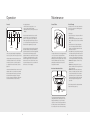
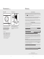
Viking Installation & Usage Guide
Viking Range Corporation
111 Front Street
Greenwood, Mississippi 38930 USA
(662) 455-1200
For product information,
call 1-888-VIKING1 (845-4641)
or visit the Viking Web site at
vikingrange.com
Designer Glass Wall Hood
F20560 EN
(120808J)
Table of Contents
Warnings & Important Information _____________________________________________________3
Planning Information _________________________________________________________________5
Wiring______________________________________________________________________________6
Hood Preparation (Ducted Configuration) ______________________________________________7
Hood Preparation (Non-Ducted Configuration) __________________________________________8
Installation __________________________________________________________________________9
Mounting Bracket ________________________________________________________________9
Hood __________________________________________________________________________10
Non-ducted Recirculation Filter ___________________________________________________11
Operation _________________________________________________________________________12
Maintenance _______________________________________________________________________13
IMPORTANT– Please Read and Follow
WARNING
Your safety and the safety of others is
very important.
FIRE AND
ELECTRICAL
SHOCK HAZARD
We have provided many important safety
messages in this manual and on your
appliance. ALWAYS read and obey all
safety messages.
To reduce the risk of fire, electric shock, or
injury to persons, observe the following:
This is the safety alert symbol. This
symbol alerts you to hazards that
can kill or hurt you and others.
• Use this unit only in the manner intended
by the manufacturer. If you have questions,
contact the manufacturer at the address or
telephone number listed in the warranty.
• Before servicing or cleaning unit, switch
power off at service panel and lock
service panel to prevent power from
being switched on accidentally. When
the service disconnecting means cannot
be locked, securely fasten a prominent
warning device, such as a tag, to the
service panel.
• Installation work and electrical wiring
must be done by a qualified person(s) in
accordance with all applicable codes and
standards, including fire-rated construction
codes and standards.
• Sufficient air is needed for proper
combustion and exhausting of gases
through the flue (chimney) of fuel burning
equipment to prevent backdrafting.
Follow the heating equipment
manufacturer’s guidelines and safety
standards such as those published by
the National Fire Protection Association
(NFPA), and the American Society for
Heating, Refrigeration and Air
Conditioning Engineers (ASHRAE), and
the local code authorities.
• When cutting or drilling into wall or
ceiling, DO NOT damage electrical wiring
and other hidden utilities.
• Ducted fans must ALWAYS be vented to
the outdoors.
• DO NOT use this unit with any separate
solid-state speed control device.
• To reduce the risk of fire, use only metal
ductwork.
• This unit must be grounded.
All safety messages will be preceded by
the safety alert symbol and the word
“DANGER,” “WARNING” or “CAUTION.”
These words mean:
DANGER
Hazards or unsafe practices
which WILL result in severe personal
injury or death
WARNING
Hazards or unsafe practices
which COULD result in severe personal
injury or death
CAUTION
Hazards or unsafe practices which
COULD result in minor personal injury
or property damage.
All safety messages will identify the
hazard, tell you how to reduce the chance
of injury, and tell you what can happen if
the instructions are not followed.
3
IMPORTANT– Please Read and Follow
WARNING
CAUTION
FIRE HAZARD
FIRE HAZARD
To reduce the risk of a range top
grease fire:
To reduce the risk of fire and to
properly exhaust air, be sure to
duct air outside.
• NEVER leave surface units unattended
at high settings. Boilovers cause smoking
and greasy spillovers that may ignite. Heat
oils slowly on low or medium settings.
• ALWAYS turn hood ON when cooking
at high heat or when flambéing food
(i.e. crepes suzette, cherries jubilee,
peppercorn beef flambé).
• Clean ventilating fans frequently. Grease
should not be allowed to accumulate on
fan or filter.
• Use proper pan size. ALWAYS use
cookware appropriate for the size of the
surface element.
• DO NOT vent exhaust air into spaces
within walls or ceilings or into attics,
crawl spaces, or garages.
Safety and Cautions
• Take care when using cleaning agents or
detergents.
• Avoid using food products that produce flames
under the range hood.
• For general ventilating use only. DO NOT use
to exhaust hazardous or explosive materials
and vapors.
• To avoid motor bearing damage and noisy
and/or unbalanced impellers, keep drywall
spray, construction dust, etc. off power unit.
• Your hood motor has a thermal overload which
will automatically shut off the motor if it
becomes overheated. The motor will restart
when it cools down. If motor continues to shut
off and restart, have the hood serviced.
• For best capture of cooking impurities, the
bottom of the hood should be a minimum of
24” and a maximum of 30” above the cooking
surface.
• Two installers are recommended because of the
large size and weight of this hood.
• This product is equipped with a thermostat
which may start blower automatically. To reduce
the risk of injury and to prevent power from
being switched on accidentally, switch power off
at service panel and lock or tag service panel.
• Please read specification label on product for
further information and requirements.
In Case of Fire
To reduce the risk of injury to persons in the
event of a range topgrease fire, observe the
following:*
• Smother flames with a close-fitting lid, cookie
sheet, or metal tray, then turn off the burner. Be
careful to prevent burns. If the flames do not go
out immediately, evacuate and call the fire
department.
• NEVER pick up a flaming pan – you may be
burned.
• DO NOT use water, including wet dishcloths or
towels – violent steam explosion will result.
• Use an extinguisher ONLY if:
o You know you have a Class ABC extinguisher
and you already know how to operate it.
o The fire is small and contained in the area
where it started.
o The fire department is being called.
o You can fight the fire with your back to an exit.
Planning Information
Prepare the hood
Install the Ductwork (Ducted Hoods ONLY)
Unpack hood and check contents.
You should receive:
1 – Hood
1 – Decorative Flue Assembly
1 – Parts Bag containing:
1 – Mounting Bracket
1 – Discharge Collar
1 – Flue Mounting Bracket
6 – Mounting Screws (4.8 x 38mm Pan Head)
7 – Mounting Screws (3.9 x 9.5mm Pan Head)
2 – Mounting Screws (3.9 x 6mm Flat Head)
6 – Drywall Anchors
1 – Installation Instructions
Note: To reduce the risk of fire, use only
metal ductwork.
Roof cap
Round duct
Decorative
flue
Hood
24” to 30” above
cooking surface
Decorative
flue
Mounting
bracket
Discharge
collar
Flue mounting
bracket
6 Drywall
anchors
6 Mounting screws
(4.8 x 38 mm pan head)
* Based on “Kitchen Fire Safety Tips” published
by NFPA.
4
Round
elbow
6” adapter
1. Decide where the ductwork will run between
the hood and the outside.
2. A straight, short duct run will allow the hood to
perform most efficiently.
3. Long duct runs, elbows, and transitions will
reduce the performance of the hood. Use as
few of them as possible. Larger ducting may
be required for best performance with longer
duct runs.
4. Install a roof or wall cap. Connect round metal
ductwork to cap and work back towards hood
location. Use duct tape to seal the joints
between ductwork sections.
7 mounting
screws (3.9 x
9.5 mm pan head)
2 Mounting screws
(3.9 x 6 mm flat head)
Wall
cap
5
Wiring
Hood Preparation (Ducted Configuration)
Note: On stainless steel hoods, carefully remove the plastic protective film from all exterior surfaces of the
hood and decorative flues, prior to final installation.
Grounding Instructions
WARNING
Note: This range hood must be properly
grounded. The unit should be installed by a
qualified electrician in accordance with all
applicable national and local electrical
codes.
1
ELECTRICAL SHOCK
HAZARD
Improper grounding can result in
a risk of electric shock.
Consult a qualified electrician if the
grounding instructions are not completely
understood, or if doubt exists as to
whether the appliance is properly
grounded. DO NOT use an extension
cord. If the power supply cord is too short,
have a qualified electrician install an outlet
near the appliance.
33-7/16"
(85cm)
Set the electrical power supply within the
space covered by the decorative flues. Position
the power socket at a maximum distance of
33-7/16” (85 cm) from where the lead exits from
the hood (see illustration). Make sure this does
not interfere with the bracket fastening area or
with the decorative flue (where the flue touches
the wall). Fit plug into power socket.
This appliance must be grounded. In the event of
an electrical short circuit, grounding reduces the
risk of electric shock by providing an escape wire
for the electric current. This appliance is
equipped with a cord having a grounding wire
with a grounding plug. The plug must be
plugged into an outlet that is properly installed
and grounded.
2
Electrical
system plate
6” diameter
duct
Discharge
collar
Duct
connector
Protection
Remove the tape on the electrical system
plate; place the electrical system plate
on the hood (use a protection).
3
Install the discharge collar into the duct connector of
the range hood. Attach an adequate length of 6”
round steel ducting to the range hood duct connector.
Upper flue vents exposed
Upper flue vents concealed
Upper
flue
Upper
flue
Lower
flue
Lower
flue
Carefully place the lower decorative flue into the recessed area of the range hood top.
Carefully slide the upper decorative flue down inside the lower flue.
Note: On 8” ceilings the air vents on the upper flue are concealed by installing the flue with air vents down.
On 9” ceilings, air vents on the upper flue will be exposed after installation.
6
7
Hood Preparation (Non-Ducted Configuration)
Note: The following materials must be purchased separately for non-ducted recirculation installations.
• Non-Ducted Recirculation Kit. (Model DGRK).
• 5” diameter expandable/flexible aluminum duct.
• 1/16” diameter twist drill.
Framing behind drywall
3.9 x 6 mm flat head
bracket screws
5-1/1
6”
CAUTION: DO NOT use plastic or metal ducting.
1
Installation (Mounting Bracket)
2
Electrical
system plate
Plenum
36-13
/16”
abov to 42-11
e coo
/
ktop 16”
(3) screws
5” aluminum
flex duct
A
10-7/
(265.6 16”
mm
36-13/16”= bottom of hood 24” above range top
42-11/16”= bottom of hood 30” above range top
)
5”-6” adapter
Blower collar
Protection
Remove the tape on the electrical system plate;
place the electrical system plate on the hood
(use a protection).
Discard discharge collar and damper supplied with the
hood. Install the 5” to 6” adapter supplied with the
Non-Ducted Recirculation Kit. Measure distance “A.”
Attach aluminum flexible duct to the 5” adapter. Tape
all joints with duct tape. Assemble the recirculation
plenum to the flex-ducting. Drill three 1/16” diameter
equally spaced holes through the duct and duct
connector of the recirculation plenum. Secure duct to
the plenum’s connector with three sheet metal screws
(not included). Tape all joints with duct tape. Carefully
place the lower decorative flue into the recessed area
of the range hood top. Carefully slide the upper
decorative flue down inside the lower flue.
Note: Air vents must be up.
3
Plenum
4 flat
head
screws
1. Assemble the flue mounting bracket, adjusting
outside width as shown.
2. Carefully center the mounting bracket directly
over the range hood location.
3. Secure the bracket assembly to the ceiling
using two 4.8 x 38 mm mounting screws and
drywall anchors. Make sure the bracket is
pushed into the corner, tight against the wall,
and centered over the hood.
1. Construct wood wall framing that is flush with
interior surface of wall studs.
Make sure:
a) the framing is centered over installation
location.
b) the height of the framing will allow the
mounting bracket to be secured to the
framing within the dimensions shown.
2. After wall surface is finished, secure mounting
bracket to framing using dimensions below.
• 36-13/16”=bottom of hood 24” above
range top
• 42-11/16”=bottom of hood 30” above
range top
Upper flue
Secure the recirculation plenum to the
upper flue with four flat head screws.
8
9
Installation (Hood)
Installation (Non-ducted Recirculation Filter)
Note: At least two people will be required to mount the hood.
1
2
Raise the hood into its
mounting position. Plug the
power cord into the electric
wall receptacle. Tuck excess
cord behind the flue.
Mounting
screws
(4.8 x 38 mm)
Mounting
screws
(3.9 x 9.5 mm)
Wall framing
Mounting
screws
(4.8 x 38 mm)
Mounting
bracket
Rectangular
cutout
Align the rectangular opening on the back of the hood with the
wall-mounting bracket. Gently lower the hood until it securely
engages the bracket. Level the hood with two mounting screws
(3.9 x 9.5 mm) and secure with two mounting screws. Use drywall
anchors provided if wall studs or framing are not available.
3
Mounting
screws
(3.9 x 9.5 mm)
4
Plate of
the
electrical
system
Mount the plate of the electrical system attaching it
with three mounting screws (3.9 x 9.5 mm).
1
Non-ducted
recirculation
filter
Purchase a non-ducted recirculation filter
from your dealer. Install the filter by pressing
the two tabs on the filter down into the
special housing and rotating upward.
3.9 x 9.5 mm
mounting screws
Raise the upper flue until its holes align with holes in
the flue mounting bracket (located on ceiling). Secure
the flue with two mounting screws.
10
11
Operation
Maintenance
Controls
LIGHT
The display indicates:
• The selected motor speed (from 1 to 4)
• Timer On when the number blinks;
• Filter Alarm when the central segments is on or
blinking.
DELAY
Light
switch
FAN
Display
Timer
switch
FILTER
Grease Filters
Hood Cleaning
Stainless steel is one of the easiest materials to
keep clean. Occasional care will help preserve
its fine appearance.
Cleaning tips:
• Hot water with soap or detergent is all that is
usually needed.
• Follow all cleaning by rinsing with clear water.
Wipe dry with a clean, soft cloth to avoid water
marks.
• For discolorations or deposits that persist,
use a non-scratching household cleanser or
stainless steel polishing powder with a little
water and a soft cloth.
• For stubborn cases, use a plastic scouring pad
or soft bristle brush together with cleaser and
water. Rub lightly in direction of polishing lines
or "grain" of the stainless finish. Avoid using
too much pressure which may mar the surface.
• DO NOT allow deposits to remain for long
periods of time.
• DO NOT use ordinary steel wool or steel
brushes. Small bits of steel may adhere to the
surface causing rust.
• DO NOT allow salt solutions, disinfectants,
bleaches, or cleaning compounds to remain
in contact with stainless steel for extended
periods. Many of these compounds contain
chemicals which may be harmful. Rinse with
water after exposure and wipe dry with a
clean cloth.
The blower switch turns the blower on and off.
Push the switch once to turn the blower ON
(turns on to last speed selected). Pushing the
switch sequentially selects blower speeds from 1
to 4. To turn the blower OFF, push and hold the
blower switch for approximately 2 seconds.
Reset
switch
Blower
switch
The reset switch resets the grease filter or charcoal
filter alarm. When the center segment blinks, the
grease filter needs to be cleaned and, if applicable,
the charcoal filter should be replaced (only
applicable when hood is installed for non-ducted
recirculation). The filter alarm will be seen in the
DISPLAY for approximately 30 seconds after the
blower is turned OFF. To reset the hour counter,
keep the switch pressed for 2 seconds when the
alarm can be seen in the display.
The hood is operated using the four push-buttons
located at eye-level, on the front edge of the hood.
The light switch turns the halogen lights on and
off. Push the light switch once to turn the lights
ON. Push a second time to turn the lights ON
to a brighter level. Push a third time to turn the
lights OFF.
Grease
filters
The grease filters must be cleaned approximately
once every 30 hours of operation (when the
central segment on the display goes on or starts
blinking). Use a warm detergent solution. Grease
filters are dishwasher safe. Remove filter by
pushing filter towards the back of hood and
rotating filter downward.
Non-ducted Recirculation Filter
The timer switch turns the blower timer on and off.
Push this switch once to turn the timer ON. With
the blower timer turned ON, the speed that was
selected will blink in the display; if the speed
selection is changed the blower timer will remain
ON; the blower will shut off after 5 minutes.
Painted surfaces should be cleaned with warm
water and mild detergent only.
Tabs
Clamp
Non-ducted
recirculation
filter
The non-ducted recirculation filter should be
changed whenever the central segment of the
display starts blinking (i.e. every 120 hours of
operation). To remove the filter, press inward on
the clamp and rotate the filter downward until
the two tabs can be removed from the housing.
12
13
Maintenance (cont.)
Warranty
Halogen Bulbs
Fuse Replacement
Fuse
ONE YEAR FULL WARRANTY
Built-in hoods/ventilators and all of their component parts, except as detailed below*, are warranted to be free from
defective materials or workmanship in normal household use for a period of twelve (12) months from the date of purchase.
NOTE: Viking Range ventilator kits are designed specifically for use with Viking Range hoods. Use of any non-Viking Range
ventilator kits VOIDS the hood warranty. Viking Range Corporation, warrantor, agrees to repair or replace, at its option, any
part which fails or is found to be defective during the warranty period.
*Glass (including light bulbs), painted, and decorative items are warranted to be free from defective materials or
workmanship for a period of ninety (90) days from the date of original retail purchase. ANY DEFECTS MUST BE REPORTED
TO THE SELLING DEALER WITHIN NINETY (90) DAYS FROM DATE OF ORIGINAL RETAIL PURCHASE.
Viking Range Corporation uses the most up-to-date processes and best materials available to produce all color finishes.
However, slight color variation may be noticed because of the inherent differences in painted parts and porcelain parts as
well as differences in kitchen lighting, product locations, and other factors.
Electrical box
SWITCH OFF THE ELECTRICITY SUPPLY.
Remove the decorative flue. Open the electrical
box. Replace with the same type of fuse (5 x 20
mm, 4A, 125V).
This range hood requires two halogen bulbs
(max 20W, 12V, Type T3 bulb, G4 Base).
ALWAYS SWITCH OFF THE ELECTRICITY
SUPPLY BEFORE CARRYING OUT ANY
OPERATIONS ON THE APPLIANCE.
To change bulbs:
1. Open the cover by prying from the proper slots.
DO NOT rotate. CAUTION: BULB MAY BE HOT!
2. Replace with a max 20W, 12V, Type T3 bulb,
G4 Base bulb. DO NOT touch replacement
bulb with bare hands! If the bulb is touched, it
should be cleaned with a lint-free cloth
moistened with methylated spirit.
FIVE YEAR LIMITED WARRANTY
Any hood/blower motor which fails due to defective materials or workmanship in normal household use during the second
through the fifth year from the date of original retail purchase will be repaired or replaced, free of charge for the part itself,
withthe owner paying all other costs, including labor.
This warranty extends to the original purchaser of the product warranted hereunder and to each transferee owner of the
product during the term of the warranty.
This warranty shall apply to products purchased and located in the United States and Canada. Products must be purchased
in the country where service is requested. Warranty labor shall be performed by an authorized Viking Range Corporation
service agency or representative. Warranty shall not apply to damage resulting from abuse, accident, natural disaster, loss of
electrical power to the product for any reason, alteration, outdoor use, improper installation, improper operation or repair or
service to the product by anyone other than an authorized Viking Range Corporation service agency or representative. This
warranty does not apply to commercial usage. Warrantor is not responsible for consequential or incidental damage whether
arising out of breach of warranty, breach of contract, or otherwise. Some jurisdictions do not allow the exclusion or limitation
of incidental or consequential damages, so the above limitation or exclusion may not apply to you.
Owner shall be responsible for proper installation, providing normal care and maintenance, providing proof of purchase
upon request, and making the appliance reasonably accessible for service. If the product or one of its component parts
contains a defect or malfunction during the warranty period, after a reasonable number of attempts by the warrantor to
remedy the defects or malfunctions, the owner is entitled to either a refund or replacement of the product or its component
part or parts. Replacement of a component part includes its free installation. Warrantor’s liability on any claim of any kind,
with respect to the goods or services covered hereunder, shall in no case exceed the price of the goods or service or part
there of which gives rise to the claim.
WARRANTY SERVICE: Under the terms of this warranty, service must be performed by a factory authorized Viking Range
Corporation service agent or representative. Service will be provided during normal business hours, and labor performed at
overtime or premium rates shall not be covered by this warranty. To obtain warranty service, contact the dealer from whom
the product was purchased, an authorized Viking Range Corporation service agent, or Viking Range Corporation. Provide
model and serial number and date of original purchase. For the name of your nearest authorized Viking Range Corporation
service agency, call the dealer from whom the product was purchased or Viking Range Corporation. IMPORTANT: Retain
proof of original purchase to establish warranty period.
The return of the Owner Registration Card is not a condition of warranty coverage. You, however, should return the Owner
Registration Card so that Viking Range Corporation can contact you should any question of safety arise which could affect
you.
Any implied warranties of merchantability and fitness applicable to the above described ventilator motor are limited in
duration to the period of coverage of the applicable express written limited warranties set forth above. Some jurisdictions do
not allow limitations on how long an implied warranty lasts, so the above limitation may not apply to you. This warranty
gives you specific rights, and you may also have other rights which may vary from jurisdiction to jurisdiction.
VIKING RANGE CORPORATION
111 Front Street • Greenwood, Mississippi 38930 USA • (662) 455-1200
14
15