1
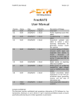
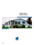
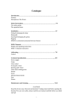
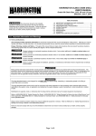
Models
BC3095
BC4100
BC4115
BC Series II
OIL-FIRED CAST IRON BOILER
INSTALLATION, OPERATION &
MAINTENANCE MANUAL
Maximum Allowable
Working Pressure 30
psi.
Manufactured by:
ECR International, Inc.
2201 Dwyer Avenue, Utica NY 13501
web site: www.ecrinternational.com
An ISO 9001-2008 Certified Company
P/N 240009511, Rev. B [12/2014]
SAFETY INFORMATION
Ratings, Data, And Dimensions������������������������������������������������������������������������ ......3
Installation Procedure������������������������������������������������������������������������������������������ 4
Ventilation And Combustion Air����������������������������������������������������������������������������� 5
Connecting Supply And Return Piping��������������������������������������������������������������������� 7
Venting System Inspection & Installation...............................................................12
Electrical Wiring������������������������������������������������������������������������������������������������ 14
Wiring Diagrams������������������������������������������������������������������������������������������������ 15
Operating Instructions��������������������������������������������������������������������������������������� 16
Maintenance Procedures������������������������������������������������������������������������������������� 18
Service Checklist����������������������������������������������������������������������������������������������� 19
! WARNING
All boiler and venting installations shall be done
by qualified agency and in accordance with
appropriate Manufacturer’s Installation, Operation
and Maintenance Manual. Installing or venting boiler
or any other appliance with improper methods or
materials could result in serious injury or death due
to fire or to asphyxiation from poisonous gases such
as carbon monoxide which is odorless and invisible.
KEEP THIS MANUAL NEAR BOILER
RETAIN FOR FUTURE REFERENCE
! WARNING
IMPORTANT: Read the following instructions
COMPLETELY before installing!!
Keep boiler area clear and free from combustible
materials, gasoline and other flammable vapors
and liquids.
Safety Symbols & Warnings
DO NOT obstruct air openings to the boiler room.
The following defined symbols are used throughout this
manual to notify the reader of potential hazards of varying
risk levels.
!
Modification, substitution or elimination of factory
equipped, supplied or specified components may
result in personal injury or loss of life.
TO THE OWNER - Installation and service of this
boiler must be performed by a qualified installer.
DANGER
Indicates a hazardous situation which, if not
avoided, WILL result in death or serious injury.
TO THE INSTALLER - Leave all instructions with
boiler for future reference.
! WARNING
Keep boiler area clear and free from combustible
materials, gasoline and other flammable vapors and
liquids.
Indicates a hazardous situation which, if not avoided,
could result in death or serious injury.
!
DO NOT obstruct air openings to boiler room.
CAUTION
To the owner: Installation and service of this boiler must
be performed by qualified installer.
Indicates a hazardous situation which, if not avoided,
could result in minor or moderate injury.
To the installer: Leave all instructions with boiler for
future reference.
NOTICE
Used to address practices not related to personal
injury.
Installation in Commonwealth of Massachusetts must be
performed by Licensed Plumber or Licensed Gas Fitter.
2
DIMENSIONS
Figure 1- Dimensions
Table 1 DIMENSIONS
Length Front of Jacket Flue
Tankless
of Flush to Center Line Outlet Coil to Back
Boiler No.
Jacket of Flue Outlet Diameter of Jacket
BC3
BC4
-A19"
23"
-B9 ¾"
11¾"
3
-C6"
6"
-D8⅞
12¾
RATINGS, DATA, AND DIMENSIONS
Table 2 RATINGS & DATA
AHRI Oil Burner
Input(1)
AHRI Net
Min. Natural Draft
Ratings(2)(4) A.F.U.E.
Chimney Size
Rating
Water MBH
Round Square
G.P.H.
MBH(4)
Heating
Capacity
MBH(4)
BC3095
0.95
133
114
99
84.0
6
8x8x15
BC4100
1.00
140
121
105
85.0
6
8x8x15
BC4115
1.15
161
137
119
84.0
6
8x8x15
Boiler Model
Number(1)
NOTES:
1. AHRI burner capacity is based on an oil heating value of 140,000 Btu/gal and with 13%
CO2.
2. Net AHRI Water Ratings shown are based on a piping and pickup allowance of 1.15.
3. Consult manufacturer before selecting boiler for installations having unusual piping and
pickup requirements, such as intermittent system operation, extensive piping.
4. For forced hot water heating systems where boiler and all piping are within the area to
be heated, select boiler on basis of its Heating Capacity.
5. Nozzle listed for use with Beckett Burner.
6. Electrical service to be 120 Volts, 15 Amps, & 60 Hz.
Table 3 TANK-LESS WATER HEATER CAPACITIES
Boiler
Model
Number
Input Tankless
Tankless Heater
Rate
Heater Capacity Intermittent
G.P.H. Number
Draw G.P.M.
Boiler
Water
Content
(Gallons)
BC3095
0.95
L-24
3.25
6.7
BC4100
1.00
L-24
3.25
8.2
BC4115
1.15
L-24
4.00
8.2
STANDARD EQUIPMENT: Crated Boiler, Flush Jacket,
Oil Burner, Target Wall/Liner, Circulator-1¼", Safety
Relief Valve, Temperature Pressure Gauge, Drain
Valve, Wiring Harness, Supply Tapping 1¼", Return
Tapping 1¼", High Limit and Circulator Control,
Primary Control. For Tankless Heater Units-add Low
Limit.
4
INSTALLATION PROCEDURE
! WARNING
!
DANGER
Improper installation, adjustment, alteration, service
or maintenance could result in death or serious
injury.
Fire hazard. Do not install boiler on combustible
flooring or carpeting. Failure to follow these
instructions WILL result in death or serious injury.
•Installation shall conform to requirements of the
authority having jurisdiction and shall take precedence
over the general instructions of this manual.
Table 4 Clearance To Combustibles
•Where required by authority having jurisdiction,
installation shall conform to Standard for Controls and
Safety Devices for Automatically Fired Boilers, ANSI/
ASME CSD-1.
•Locate boiler in front of final position before removing
crate. Provide solid level base as near chimney as
possible and centrally located with respect to the heat
distribution system as practical.
TOP
24 IN.
FRONT
24 IN.
FLUE CONNECTOR
9 IN.
REAR
6 IN.
LEFT SIDE
6 IN.
RIGHT SIDE
24 IN.
NOTE: Clearance for access should exceed fire protection
clearance.
•Allow 24 inches in front, top and right hand side for
servicing and cleaning or removing tankless water
heating coil.
•When installed in utility room, door should be wide
enough to allow largest boiler part to enter, or to permit
replacement of another appliance such as water heater.
•Boiler shall be installed such that the oil ignition system
components are protected from water (dripping,
spraying, rain etc.) during appliance operation and
service.
•Remove crate and plastic protective wrapper, inspect for
damage.
•Move boiler to permanent position by sliding or walking.
5
VENTILATION AND COMBUSTION AIR
Table 5 COMBUSTION AIR REQUIREMENTS
(Minimum Opening Requirement)
BTU/Hr
Input
Outside
Unconfined Area*
(Mbh)
Combustion Air 1 Sq.
In./5000 BTU/Hr
(Step 4)
133
140
161
27
28
32
Inside
Combustion Air 1 Sq.
In./1000 BTU/Hr
(Min. 100 Sq. In.)
133
140
161
Confined Area**
Outside Combustion Air
Vertical Ducts 1 Sq.
In./4000 BTU/Hr
Horizontal Ducts 1 Sq.
In./2000 BTU/Hr
(Figures 2 & 3)
(Figure 4)
33
35
40
67
70
81
* A space whose volume is not less than 50 cubic feet per 1000 BTU/Hour of all appliances installed in that space (cubic feet of space = height x
width x length)
** A space whose volume is less than 50 cubic feet per Mbh of all appliances installed in that space (cubic feet of space = height x width x
length)
! WARNING
4. When air for combustion and room ventilation is from
Asphyxiation, fire hazard. Air openings to combustion
area SHALL not be obstructed. Provide adequate
supply of combustion air in accordance with
Installation Code for Oil Burning Appliances, CSA
139.
inside buildings, the confined space shall be provided
with two permanent openings, one starting 12 inches
from the top and one 12 inches from the bottom of the
enclosed space. Each opening shall have a minimum
free area of 1 square inch per 1,000 BTU per hour of
the total input rating of all appliances in the enclosed
space, but must not be less than 100 square inches.
These openings must freely communicate with the
interior areas having adequate infiltration from the
outside. See Figure 2.
! WARNING
Asphyxiation, fire hazard. Do not obstruct air
openings to combustion area. Follow instructions
below, to maintain adequate combustion air.
1. Ventilation of boiler room must be adequate enough to
provide sufficient air to properly support combustion
and venting.
2. When the boiler is located in an unconfined space in a
building of conventional construction frame, masonry
or metal, infiltration normally is adequate to provide
air for combustion and ventilation. However, in any
building which has been altered to conserve energy
or to minimize infiltration, the boiler area should
be considered as a confined space. If there is any
doubt, install air supply provisions for combustion and
ventilation in accordance with requirements of authority
having juridiction, or in absence of such requirements,
Air for Combustion and Ventilation of the NFPA 31.
Figure 2Combustion and Room Air From Inside
Buildings
CHIMNEY
OR
L TYPE VENT PIPE
BASEBOARD
3. When the boiler is installed in an unconfined space,
in a building of unusually tight construction, air for
combustion and room ventilation must be obtained
from outdoors or from spaces freely communicating
with the outdoors. A permanent opening or openings
having a total free area of not less than 1 square inch
per 5,000 BTU per hour of total input rating of all
appliances shall be provided. Ducts may be used to
convey make-up air from the outdoors and shall have
the same cross-sectional area of the openings to which
they are connected.
VENT PIPE
12"
VENTS
12"
6
VENTILATION AND COMBUSTION AIR
5. When the boiler is installed in a confined space and
Figure 3Boiler Installed In Confined Space - Air
From Outdoors
all air is provided from the outdoors, the confined
space shall be provided with two permanent openings,
one commencing within 12 inches from the top and
one commencing 12 inches from the bottom of the
enclosure. The openings shall communicate directly, or
by ducts, with the outdoors or spaces (crawl or attic)
that freely communicate with the outdoors. One of the
following methods must be used to provide adequate
air for ventilation and combustion.
A. When directly communicating with the outdoors,
each opening shall have a minimum free area
of 1 square inch per 4,000 BTU per hour of total
input rating of all equipment in the enclosure. See
Figure 3.
B. When communicating with the outdoors by means
of vertical ducts, each opening shall have a minimum free area 1 square inch per 4,000 BTU per
hour of total input rating of all appliances in the
enclosed space. See Figure 4.
C. If horizontal ducts are used, each opening shall
have a minimum free area 1 square inch per 2,000
BTU per hour total input rating of all appliances in
the enclosed space. See Figure 5.
Figure 4Vertical Ducts
D. When ducts are used, they shall be of the same
cross sectional area as the free area of the area of
the openings to which they connect. The minimum
dimension of rectangular air ducts shall not be less
than 3 inches.
6. In calculating free area using louvers, grills or screens
for the above, consideration shall be given to their
blocking effect. Screens used shall not be smaller than
1/4 inch mesh. If the free area through a design of
louver or grill is known, it should be used in calculating
the size opening required to provide the free area
specified. If the design and free area is not known, it
may be assumed that wood louvers will have 20-25%
free area and metal louvers and grills will have 60-75%
free area. Louvers and grills shall be fixed in the open
position or interlocked with the boiler so that they are
opened automatically during boiler operation.
Figure 5Horizontal Ducts
7
CONNECTING SUPPLY AND RETURN PIPING
Circulators in the following illustrations are mounted on
system supply side, mounting on system return side is also
acceptable practice.
Figure 6Boiler Used In Connection With Refrigerated System
Figure 7Bypass Piping Typically Used With Baseboard Heating
1. Connect supply and return piping as suggested in
B. Use appropriate valves to prevent chilled medium
from entering heating boiler.
2. During the heating cycle open valves A and B, close
valves C and D.
Figure 6. When the boiler is used in connection with
refrigerated systems:
A. Chilled medium MUST BE IN PARALLEL with
boiler.
8
CONNECTING SUPPLY AND RETURN PIPING
3. During heating cooling cycle open valves C and D, close
B. This method is used to protect boilers from
condensate forming due to low temperature return
water. Generally noticed in large converted gravity
systems or other large water volume systems. See
Figure 8.
valves A and B.
A. Maintain a minimum clearance of one (1") inch to
hot water pipes. In air handling units where they
may be exposed to refrigerated air circulation, the
boiler piping system MUST be supplied with flow
control valves or other automatic means to prevent
gravity circulation of the boiler water during the
cooling cycle.
4. Hot water boilers installed above radiation level must
be provided with a low water device either as part of
the boiler or at the time of boiler installation.
5. When a boiler is connected to a heating system that
utilizes multiple zoned circulators, each circulator must
be supplied with a flow control valve to prevent gravity
circulation.
C. This method is used to protect boilers from
condensate forming as well as protecting the
heating system from high water temperature. See
Figure 9, page 9.
7. Note: When using bypass piping, adjust valves A and
B until desired system temperature is obtained.
8. Bypass loop piping must be same size piping for supply
and return.
9. Typical installation using circulators is shown in
Figure 10, page 9.
10. Typical installation using zone valves is shown in
* Reduced pressure back flow preventer must be
present under provisions required by the Environmental
Protection Agency, (EPA).
Figure 11, page 10.
11. See Figure 12, page 10 for typical piping for domestic
hot water heater.
6. Bypass piping is an option which gives the ability to
adjust the supply boiler water temperature to fit the
system or condition of the installation. Although, this
method of piping is not typically required for baseboard
heating systems.
A. This method is used to protect systems using
radiant panels and the material they are encased
in from high temperature supply water from the
boiler. See Figure 7, page 7.
Figure 8Bypass Piping Option For Converted Large Volume Systems
9
CONNECTING SUPPLY AND RETURN PIPING
Figure 9Bypass Piping Option Used to Protect From Converted Systems With High Water
Temperature
Figure 10
Typical Installation With Circulators
10
CONNECTING SUPPLY AND RETURN PIPING
Figure 11
Typical Installation With Valves
Figure 12
Typical Installation With DHW
11
CONNECTING SUPPLY AND RETURN PIPING
!
WARNING
Burn or Scald Hazard. Discharge line shall be installed to relief valve outlet connection to avoid burns,
scalding, or water damage due to discharge of steam and/or hot water during operation.
Discharge line shall:
•Use ¾" or larger pipe.
•Use pipe suitable for temperatures of 375°F (191°C) or greater.
•Individual boiler discharge piping shall be independent of other discharge piping.
•Size and arrange discharge piping to avoid reducing safety relief valve relieving capacity below
minimum relief valve capacity stated on rating plate.
•Run pipe as short and straight as possible to location protecting user from scalding and properly drain
piping.
•Install union, if used, close to safety relief valve outlet.
•Install elbow(s), if used, close to safety relief valve outlet and downstream of union (if used).
•Terminate pipe with plain end (not threaded).
Refer to local codes and appropriate ASME Boiler and Pressure Vessel Code for additional installation
requirements.
12. Install limit sensor in supply pipe. See Figure 13.
Figure 14
• Install nipple and tee.
• Install well in tee.
• Insert sensor into well. Secure with clip.
Safety Relief Valve With Discharge
Line
Safety Relief Valve
• Secure sensor wire to jacket with cable clamps.
• Plug sensor wire into limit. See wiring diagram.
Discharge Line
13. Install safety relief valve. See Figure 14.
• Install safety relief valve in rear section using
provided nipple and elbow.
• Install discharge piping. Follow instructions in
Warning above.
Figure 13
Tee
Limit Sensor
Well
Check local codes
for maximum
distance from floor
or allowable safe
point of discharge.
Limit Sensor
Supply
Pipe
Cable
Clamps
Temperature
Pressure Gauge
Limit
12
VENTING SYSTEM INSPECTION & INSTALLATION
!
WARNING
!
WARNING
Figure 15
Chimney Installation
Boiler and venting installations shall be performed
by a qualified expert and in accordance with the
appropriate manual. Installing or venting boiler
or other appliances with improper methods or
materials may result in serious injury or death due
to fire or to asphyxiation from poisonous gases such
as carbon monoxide with is odorless and invisible.
Do not connect boiler to any portion of mechanical
draft system operating under positive pressure.
•Inspect chimney. Verify construction supplies with
requirements of authority having jurisdiction, or in
absence of such requirements, NFPA 211: Standard
for Chimneys, Fireplaces, Vents and Solid Fuel-Burning
Appliances.
•Install boiler into chimney which has masonry or metallic
chimney liner.
Table 6 CHIMNEY OR VENT SIZES
•Unlined chimney will have leaks that will cause poor
chimney performance (no draft), and could result in
positive pressure in the combustion chamber.
MODEL NUMBER
BC3
BC4
•Horizontal portions of venting system should not exceed
10 ft. in length. Horizontal lengths over 10 ft. will have
negative effect on chimney performance.
•Chimney should extend at least 2 ft. above any portion
of building within 10 ft. See Figure 15. It should produce
a -.06 to -.08 inch W.C. draft, as measured with draft
gauge between boiler and barometric draft control while
maintaining .02 inch W.C. negative draft in combustion
chamber. . See "Chimney or Vent Sizes" chart for
recommended minimum and maximum chimney or vent
sizes.
•Inadequate draft will cause improper combustion,
resulting in dirty flue ways and high fuel bills.
•Connect flue pipe same size as boiler outlet to chimney,
sloping upward continuously toward the chimney
approximately ¼" per foot. Bolt or screw joints together
to avoid sag.
•If oil fired water heater is vented into same flue as boiler,
provide separate hole into chimney whenever possible.
When this isn’t possible, use “Y” connection in flue
pipe, using separate draft regulator for each unit. When
chimney will not provide adequate draft to handle input
from water heater and boiler simultaneously, wire units
so only one will operate at a time, favoring water heater.
13
ROUND
INCHES
MIN MAX
6
8
6
8
SQUARE
HEIGHT (FT)
INCHES
MIN MAX MIN MAX
8x8 8x10
15
40
8x8 8x10
15
40
OIL TANK AND PIPING
Oil Tank and Piping Installation
•Install oil tank and piping in accordance with the National
Board of Fire Underwriters and local regulations.
•Oil storage tank, vent, fill pipe and caps should be as
prescribed by local codes. In no case should the vent pipe
be smaller than 1¼" I.P.S. The fill pipe should not be less
than 2" I.P.S.
•Suction line from tank to burner shall be one continuous
piece of tubing to prevent air entering the line.
A. Suction line, must be ⅜" O.D. copper tubing for runs
of 50 feet or less, and ½" O.D. for longer runs.
B. Install oil return line same size suction line. Use on
any installation where bottom of tank is below fuel
unit of burner.
C. Oil lines should be buried or otherwise protected from
mechanical injury.
D. Flare fittings on all oil lines are recommended.
E. Compression fittings on suction line often allows air
to be drawn into fuel pump, making it difficult to
maintain oil pressure at the nozzle.
F. Do not run overhead fuel lines from tank to oil
burner.
Figure 16
Typical Installation Single Pipe Oil
System
•Install fuel pump connections and by-pass according to
instructions attached to the fuel pump. If tank is more
than 20' from boiler, install two stage fuel unit in place
of single stage pump supplied as standard equipment
with burner. Verify rotation and speed are same and
pump is suitable for burner horsepower rating.
•Install oil line filter and shut-off valve in suction line.
Install shut-off valves in both suction and return lines
at burner for servicing burner. Allow extra tubing at
burner so burner may be removed from boiler for
cleaning without disconnecting tubing. See Figure 16 and
Figure 17.Optional flexible oil line is available.
Figure 17
14
Typical Installation Two Pipe Oil
System
ELECTRICAL WIRING
! WARNING
Electrical shock hazard. Turn OFF electrical power
supply at service panel before making electrical
connections. Failure to do so could result in death
or serious injury.
Install electrical wiring in accordance with requirements
of authority having jurisdiction, or in the absence of such
requirements, NFPA 70: National Electric Code.
A separate electrical circuit should be run from the entry
box with a fused disconnect switch in this circuit. See
wiring diagram See Figure 18 .
Thermostat Installation
1. Thermostat should be installed on an inside wall about
four feet above the floor.
2. NEVER install a thermostat on an outside wall.
3. Do not install a thermostat where it will be affected
by drafts, hot or cold pipes, sunlight, lighting fixtures,
television, fireplaces, or chimneys.
4. Check thermostat operation by raising and lowering
thermostat as required to start and stop the burner.
5. Instructions for the final adjustment of the thermostat
are packaged with the thermostat (adjusting heating
anticipator, calibration, etc.).
Wiring for zone valve installations are furnished with zone
valve packages.
15
WIRING DIAGRAMS
16
·
Wiring Diagram
·
Figure 18
OPERATING INSTRUCTIONS
Sequence of Operation
•Thermostat calls for heat.
•Circulator turns on.
•Limit checks boiler water temperature. Burner ignition
delayed until limit determines call for heat cannot be met
by residual heat in boiler and heat distribution system.
A.See limit literature for additional information.
B.Burner delay by-passed for tankless heat call for
heat. Burner ignition begins immediately.
•Burner and circulator operation continues until
thermostat stops call for heat.
Figure 19
Boiler Controls
JACKET TOP PANEL
TEMPERATURE
PRESSURE GAUGE
LIMIT
CONTROL
UPPER FRONT
JACKET PANEL
1/4" SLOT
WIRE HARNESS
CIRCULATOR
HOT
LOWER FRONT
JACKET PANEL
OIL BURNER
WIRE HARNESS
BURNER
A1454
17
OPERATING INSTRUCTIONS
!
Burner Operation Instructions
WARNING
•Use provided ¼" diameter slot in inspection cover plate
to take draft readings in combustion chamber. See
Figure 19, page 16.
Boiler and venting installations shall be performed
by a qualified expert and in accordance with the
appropriate manual. Installing or venting boiler
or other appliances with improper methods or
materials may result in serious injury or death due
to fire or to asphyxiation from poisonous gases such
as carbon monoxide with is odorless and invisible.
•Drill ¼" diameter hole in flue pipe between boiler and
barometric damper (if used) to take draft, CO2, smoke
and temperature readings. Plug hole when done.
•Adjust air shutter on oil burner to obtain “trace” of
smoke. Measure CO2 at this point.
•Increase air adjustment to lower CO2 approximately one
percent.
Start-Up And Adjustment Of Oil Burner
NOTE: Bacharach or Dwyer test kits include these
instruments.
•Verify minimum negative .02 w.c., (water column),
“overfire” draft and zero smoke.
(See oil burner instructions for nozzle and electrode setting)
1. Verify oil burner nozzle is tight in adapter. Burner
2.
3.
4.
5.
6.
7.
8.
9.
•If -.02 w.c. “overfire” draft can not be maintained,
changes and/or modifications may be required in venting
or chimney.
mounting bolts should be tight.
Check electrode setting, may have been jarred out of
position during transportation.
Lubricate burner motor if necessary.
Set room thermostat to call for heat, or jump
thermostat contacts on boiler control.
Open all oil line valves.
Turn service switch on. Burner will start.
On one pipe fuel systems only, bleed pump as soon as
burner starts. Allow oil to run until all traces of air in
suction line disappear.
Turn “OFF” burner and install pressure gauge port on
pump.
Start burner and check oil pressure for 140 psi adjust if
necessary.
•See table below as guideline for initial start-up. Make
final adjustments using combustion instruments.
Check safety control circuit after burner adjustments
have been made for satisfactory performance.
A. High limit control: remove cover and note
temperature setting. See Figure 19, page 16. With
burner operating, decrease setting to minimum
point. When boiler water temperature exceeds set
point, high limit switch will open, shutting off power
to oil burner. Return setting to desired high limit
point. Burner should start.
B.Verify Primary Control and Flame Sensor •Flame Failure - simulate by shutting off oil supply
with hand valve while burner is on. Sixty seconds after
flameout, safety switch locks out, ignition stops, motor
stops and oil valve - when used - closes. To restart,
open oil supply valve and reset safety switch.
•Ignition Failure - With burner off, close oil supply
valve and run through start-up procedure. Safety
switch should lock out as in flame failure.
•Power Failure - Turn off main power supply switch
while burner is operating. When burner stops, restore
power and burner should start. If operation is not as
described as above, check wiring and controls.
Boiler
Model
No.
BC3095
BC4100
BC4115
Table 7 Oil Burner Settings
Head
Type
Static
Disc
F3
F3
F6
2¾ U
2¾ U
2¾ U
Air Band Air Shutter
Nozzle Furnished
Settings Settings
0
0
0
6
7
6
Delevan 0.85x 80°B
Delevan 0.85x 80°B
Delevan 1.00x 80°B
Pump Pressure
(psi)
140
140
140
NOTES:
Information in above table uses Beckett model AFG burner for both model numbers BC-3 and . BC-4
BC4115 is rerated boiler which requires rerate kit.
18
MAINTENANCE PROCEDURES
Regular Maintenance
NOTICE
•Inspect venting system at start of each heating season.
Check vent pipe from boiler to chimney for signs
of deterioration by rust or sagging joints. Repair if
necessary.
Do not overtighten bolts.
Periodic inspection and tightening of tankless heater/
cover plate bolts reduce the risk of leaks. CAUTION: Do not
overtighten bolts.
•Remove vent pipe at base of chimney or flue. Use mirror,
check for obstruction.
Instructions For Removing Oil Burner
•Verify compliance to the latest revision of the NFPA 211.
1.
2.
3.
4.
5.
•Operate lever of safety relief valve on boiler periodically
to verify that it is functioning properly. Open pressure
relief valve before water pressure exceeds 30 psi reading
on gauge. If pressure is exceeded and pressure relief
valve leaks water when boiler is operating at normal
pressures, replace immediately. Corrosion can build at
valve seat and prevent functioning as safety device.
Periodically or at start of heating season inspect boiler, vent
and vent pipe for accumulation of soot or scale deposits.
When soot is present on section walls and flueways,
improper combustion results, causing additional sooting
and scaling until flueways are completely closed.
B. Carefully vacuum debris from combustion chamber.
Inspect combustion chamber for signs of damage, i.e.
cracks.
C. In event combustion chamber is damaged, contact
qualified service agent to replace immediately.
Allow boiler to cool down.
Remove three (3) 1/2" nuts from burner flange.
Close oil valve. See Figure 16 and Figure 17, page 13.
Disconnect oil line from burner.
Recommend replacing nozzle at start of each heating
season.
Annual Inspection - Before Start of Heating Season
A. To remove soot and scale from flueways, remove
top jacket panel, top clean-out plate and burner. See
instructions on Removing Oil Boiler. Use wire brush,
brush soot and scale into combustion chamber where
it can be removed through burner opening.
Turn off power to boiler.
Lubricate burner motor and circulator motor - if required with few drops of good grade of light motor oil. Do not over
oil.
Have qualified service agent service burner and check
controls and electrodes for carbon or cracks in insulators.
Adjust burners to produce conditions shown in Start-up and
Adjustment of Oil Burner procedure.
Instructions For Replacing Oil Burner
1.
2.
3.
4.
19
Reconnect oil line.
Open oil valve. See Figure 16 and Figure 17, page 13.
Install and tighten three (3) 1/2" nuts on burner flange.
Turn on power to boiler.
SERVICE CHECKLIST
Inspect Chimney and Flue Pipe
Inspect and Clean Appliance
Inspect Oil Line - Size/Leaks
Inspect Electrical Connections
Install New Filter
Room Make-up Air
Electrode Setting
Proper Light-Off (Hot & Cold)
[
[
[
[
[
[
[
[
X
X
X
X
X
X
X
X
]
]
]
]
]
]
]
]
Controls and Safety Devices
Nozzle-Size, Angle, Type
Pump Pressure/Vacuum
Line Voltage/Motor Amps
Smoke Test
Draft-Overfire/In Flue
CO2 or O2
Flue Gas Temperature
[
[
[
[
[
[
[
[
X
*
*
*
*
*
*
*
]
]
]
]
]
]
]
]
* Measure with instruments and record results below.
SERVICE RECORD
Date
Nozzle
Size
Angle
Pump Pressure
Smoke#
PSI
Type
Draft
O.F.
INF
CO2
Flue
or O2
Temp °F
UTICA BOILERS
2201 Dwyer Avenue
Utica NY 13501
web site: www.ecrinternational.com