1
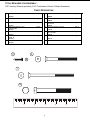
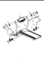
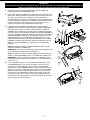
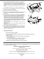
T35 Treadmill
A S S E M B L Y
I N S T R U C T I O N S
T35 Treadmill
A S S E M B L Y
I N S T R U C T I O N S
Congratulations...
and welcome to the world of Life
Fitness
and the Life Fitness T35 treadmill.
The following Parts Identification Listing and the step by step assembly procedures
have been assembled to make the set-up of this treadmill as quick and easy as
possible.
Please take special note of the following important points prior to choosing a location
and beginning assembly of the treadmill…
2
IMPORTANT SAFETY INSTRUCTIONS !
⇒
DO NOT position the rear of the treadmill within 6 feet ( 2 meter ) of the nearest obstruction. The
sides of the treadmill should maintain a minimum clearance of 8 inches ( 20 cm ) from the nearest
treadmill or other obstruction.
⇒
DO NOT locate the treadmill outdoors, near swimming pools, or in areas of high humidity.
⇒
DO verify the contents of the delivery carton against the accompanying parts listing prior to setting the
cartons and shipping material aside. If any parts are missing, contact Life Fitness Customer Support
Services at the number listed on the back page of this assembly instruction booklet.
Save the shipping cartons in case of return.
⇒
DO read the entire Operation Manual prior to attempting to operate this machine, as this is essential for
proper use. The Manual explains how to properly use the treadmill and helps you to design an aerobic
workout tailored to your personal fitness needs or requirements.
⇒ NE PAS placer l’arrière de l’appareil à moins de 2 m (3 pi) de toute obstruction. Conserver un
dégagement latéral minimum de 20 centimètres (8 pouces) entre deux appareils ou entre l’appareil et
tout autre type d’obstruction.
⇒
⇒ NE PAS placer le tapis roulant à l’extérieur, près d’une piscine ou dans un endroit très humide.
⇒ VÉRIFIER si l’emballage contient toutes les pièces de la liste jointe avant de le mettre de côté. Si des
pièces manquent, téléphoner au service après-vente de Life Fitness dont le numéro figure sur la
couverture arrière de la brochure de montage.
Conserver l’emballage au cas où l’appareil devrait être renvoyé.
⇒ LIRE le manuel de l’utilisateur tout entier avant d’essayer de faire fonctionner cet appareil. Ceci est
indispensable à son utilisation correcte. Le manuel explique comment utiliser correctement le tapis
roulant et permet de préparer une séance d’exercice adaptée aux critères et aux besoins de chacun.
3
TOOLS REQUIRED FOR ASSEMBLY...
5/32” Hex Key Wrench (provided), 9/16” Combination Wrench, Phillips Screwdriver
PARTS DESCRIPTION
1
USER LEFT UPRIGHT
Qty: 1
2
USER RIGHT UPRIGHT
Qty: 1
3
7966701
DISPLAY CONSOLE ASSEMBLY
Qty: 1
4
7966501
HANDRAIL (LEFT & RIGHT)
Qty: 2
5
TOP HANDRAIL SPACER
Qty: 2
6
Qty: 8
8
Qty: 1
10
Qty: 2
12
7
9
11
13
7127201
MOUNTING SCREW (LONG)
1/4 - 20 x 4.25”
3207701
HANDRAIL CROSSBAR
7966101
MOTOR COVER SCREW
6-20 x .38
3207501
UPPER HANDRAIL COVER
7966301
MOUNTING SCREW (SHORT)
1/4 - 20 x 3”
3208001
BOTTOM HANDRAIL SPACER
Qty: 2
Qty: 2
7127101
UPRIGHT MOUNTING BOLT
3/8 - 16 x 3.25”
3223310
STOP CORD
Qty: 4
Qty: 1
6841301
Qty: 2
7127401
11
6
7
10
1”
2”
3”
4
4”
5”
5
3
9
5
7
4
2
1
8
13
6
4
10
8
7
5
IMPORTANT!
DO NOT DISCARD THE SHIP KIT LOCATED ON TOP OF THE DECK AND BELT. ALL NECESSARY COMPONENTS NEEDED TO
COMPLETE THE INSTALLATION ARE LOCATED IN THE SHIP KIT AND BASE TRAY.
1. Remove the tape securing the MOTOR COVER (A) to the FRAME (B).
A
Carefully lift and remove the MOTOR COVER.
2. Remove the USER LEFT UPRIGHT (#1) (with grommets installed) from the
BASE TRAY. With the USER LEFT UPRIGHT angled toward the rear of the
unit, align the mounting holes of the flanged end of the USER LEFT
UPRIGHT with those on the top of the FRAME (B). Using two BOLTS (#10),
secure the USER LEFT UPRIGHT to the FRAME. Tighten the BOLTS using
a 9/16” combination wrench until snug and then back them off 1/4 turn.
Repeat the procedure for the USER RIGHT UPRIGHT (#2).
B
3. Locate the DISPLAY CONSOLE ASSEMBLY (#3). Unwrap the WIRE
HARNESS (C) secured to the back of the DISPLAY CONSOLE ASSEMBLY.
Standing at the front of the unit, carefully lower the DISPLAY CONSOLE
ASSEMBLY down near the tops of the USER LEFT and RIGHT UPRIGHTS
(#1 & #2). Lower the user right side of the DISPLAY CONSOLE ASSEMBLY to
rest on the USER RIGHT UPRIGHT. Holding the user left side of the DISPLAY
CONSOLE ASSEMBLY slightly above the USER LEFT UPRIGHT, feed the
WIRE HARNESS down into the USER LEFT UPRIGHT through the TOP
CABLE ROUTING HOLE (D) of the USER LEFT UPRIGHT. Once the WIRE
HARNESS is completely inserted into the USER LEFT UPRIGHT, lower the
DISPLAY CONSOLE ASSEMBLY to completely rest on the USER LEFT
UPRIGHT.
NOTE: Be careful not to damage the WIRE HARNESS (C) when routing it
through the USER LEFT UPRIGHT (#1).
REMARQUE : Veiller à ne pas endommager le faisceau de CABLES (c) lors
de son passage par le MONTANT DE GAUCHE (nº 1).
NOTE: Be careful not to pinch the WIRE HARNESS (C) when lowering the
DISPLAY CONSOLE ASSEMBLY (#3) onto the USER LEFT UPRIGHT (#1).
REMARQUE : Veiller à ne pas pincer le faisceau de CABLES (c) lors de
l’abaissement de la CONSOLE D’AFFICHAGE (nº 3) sur le MONTANT DE
GAUCHE (nº 1).
4. Locate a HANDRAIL (#4) and a TOP HANDRAIL SPACER (#5). Insert a
LONG MOUNTING BOLT (#7) through the bottom most of the two top
mounting holes of the HANDRAIL as shown. Slide a TOP HANDRAIL
SPACER over the LONG MOUNTING BOLT as shown (flat side facing the
upright and cutout facing downward) until it fully nests over the HANDRAIL.
Align and insert the same LONG MOUNTING BOLT into the bottom most
mounting hole of the USER RIGHT UPRIGHT (#2). Tighten the bolt until
snug and then back it off one full turn. Insert a LONG MOUNTING BOLT
(#7) through the remaining (upper) mounting hole and tighten the two bolts
securely using a 5/32” hex key wrench.
1
10
B
3
C
D
1
7
5
2
4
6
5. Locate a BOTTOM HANDRAIL SPACER (#8). Slide the BOTTOM
HANDRAIL SPACER onto the bottom of the USER RIGHT HANDRAIL (#4)
with the flat side of the BOTTOM HANDRAIL SPACER facing the FRAME
(B). Align the two mounting holes in the HANDRAIL, BOTTOM HANDRAIL
SPACER, and FRAME and insert two LONG MOUNTING BOLTS (#7) and
tighten securely using a 5/32” hex key wrench.
6. After securing the USER RIGHT SIDE HANDRAIL (#4) to the USER
RIGHT UPRIGHT (#2), remove the USER LEFT UPRIGHT rear
mounting bolt and carefully twist THE USER LEFT UPRIGHT (#1)
outward until the rear mounting flange is off of the FRAME (B).
4
NOTE: Be careful not to tilt the USER LEFT UPRIGHT (#1) from under the
DISPLAY CONSOLE (#3) when twisting the USER LEFT UPRIGHT outward.
7
B
REMARQUE : Veiller à ne pas incliner le MONTANT DE GAUCHE (nº 1)
sous la CONSOLE D’AFFICHAGE (nº 3) lors de son orientation vers
l’extérieur.
7.
8
Reach a finger up into the ACCESS HOLE (E) located under the USER
LEFT UPRIGHT mounting flange and guide the 10-PIN CONNECTOR (10P)
of the WIRE HARNESS (C) that was fed into the USER LEFT UPRIGHT
through the BOTTOM CABLE ROUTING HOLE (F) of the USER LEFT
UPRIGHT. Carefully pull the excess wire from within the USER LEFT
UPRIGHT. Plug the 10-PIN CONNECTOR into the CONTROL BOARD (G)
located in the MOTOR COMPARTMENT (H). Feed any excess wire back into
the USER LEFT UPRIGHT.
D
NOTE: Be careful not to damage the WIRE HARNESS (C) when pulling it
through the BOTTOM CABLE ROUTING HOLE (F) in the USER LEFT
UPRIGHT (#1).
3
1
REMARQUE : Veiller à ne pas endommager le faisceau de CABLES (C) lors
de son passage dans L’ORIFICE D’ACHEMINEMENT DE CABLES
INFERIEUR (F) du MONTANT DE GAUCHE (nº 1).
8. Carefully twist the USER LEFT UPRIGHT back into position on the FRAME (B)
B
and re-insert the rear MOUNTING BOLT (#10). Tighten the BOLT using a
9/16” combination wrench until snug and then back it off 1/4 turn.
NOTE: Be careful not to damage the WIRE HARNESS (C) when twisting the
USER LEFT UPRIGHT (#1) back into position.
REMARQUE : Veiller à ne pas endommager le faisceau de CABLES (C) lors
de la remise en place du MONTANT DE GAUCHE (nº 1).
10P
C
F
9. Repeat Steps 4 and 5 to assemble the USER LEFT HANDRAIL.
1
Tighten all mounting bolts and then back them off one full turn.
E
B
H
G
10P
7
C
F
1
10. Locate the HANDRAIL CROSSBAR (#9). With the bend facing upward and
pitched toward the DISPLAY CONSOLE, carefully place the HANDRAIL
CROSSBAR between the user LEFT AND RIGHT HANDRAILS (#4) as shown
and align the mounting holes. Insert one SHORT MOUNTING BOLT (#6) on
either end of the HANDRAIL CROSSBAR and tighten using a 5/32” hex key
wrench.
13
12
13
Securely tighten all mounting bolts on the USER LEFT HANDRAIL (#4).
11. Securely tighten the four MOUNTING BOLTS (#10) securing the USER LEFT
and RIGHT UPRIGHTS to the FRAME (B).
12. Place the STOP CORD (#12) in the proper location.
6
9
13. Position the unit in the desired location and plug the power cord into the front of
4
the unit and then into a wall outlet (See the operation manual for power
requirements.)
14. Position the MOTOR COVER (A) back over the MOTOR COMPARTMENT
(H). Bring the unit to an incline position (refer to the Operation Manual for
proper start and incline procedures.) Secure the MOTOR COVER (A) to the
FRAME (B) using the two MOTOR COVER SCREWS (#11). Tighten the
screws securely. Press down on the MOTOR COVER at the positions
indicated to secure the Dual-Lock fasteners located under the MOTOR
COVER to the FRAME. Lift lightly on the MOTOR COVER to confirm a positive
lock. Repeat as necessary until the MOTOR COVER is secure. Lower the unit
back to its original level.
A
Press
Press
NOTE: Be careful not to pinch the WIRE HARNESS (C) when replacing the
MOTOR COVER (a).
REMARQUE : Veiller à ne pas pincer le faisceau de CABLES (C) lors de la
remise en place du CAPOT DU MOTEUR (A).
11
B
15. Place an UPPER HANDRAIL COVER (#13) on the top of each HANDRAIL
(#4). Align the tabs of the UPPER HANDRAIL COVERS with the slots in the
TOP HANDRAIL SPACERS (#5) and apply light pressure until the UPPER
HANDRAIL COVERS snap secure.
PRE-OPERATION CHECKLIST
Ensure that all fasteners are tight.
Make sure the STRIDING BELT is properly tensioned and aligned according to the
Operation Manual.
Check the operation of the STOP switch and tether switch assembly.
(See Operation Manual.)
Confirm the display console is set to English or Metric units.
(See Optional Settings ENG/MET in Operation Manual.)
Read the entire Operation Manual before using the treadmill.
Before attempting to operate your Treadmill, it is imperative that you familiarize yourself with the contents of the Operation Manual.
If your Life Fitness treadmill does not respond as described in the OPERATION MANUAL contact the nearest Life Fitness Service
Center as listed in the OPERATION MANUAL.
Life Fitness Customer Support Services
at (800) 351-3737
Prior to your call, please be sure you have located and noted the
MODEL NUMBER & SERIAL NUMBER.
The Model & Serial number information of your Life Fitness Treadmill is contained in a label
located on the front of the unit.
©2005 Brunswick Corporation. All rights reserved. Life Fitness is a trademark of Brunswick Corporation.
7995101 Rev A2
12/05
8