1
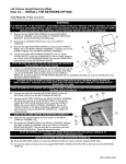
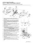
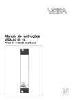
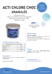
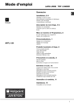
95Ce Upright Exercise Bike
Assembly Instructions
Congratulations...
and welcome to the world of
The following Parts Identification Listing and the step by step assembly
procedures have been assembled to make the set-up of the Upright Exercise Bike
as quick and easy as possible.
Please take special note of the following important points prior to choosing a
location and beginning assembly of the Upright Exercise Bike.
IMPORTANT SAFETY INSTRUCTIONS!
⇒
DO NOT locate the Exercise Bike outdoors, near swimming pools, or in areas of high humidity.
⇒
DO NOT operate your Exercise Bike if it has been dropped, damaged, or even partially immersed
in water. Contact Life Fitness Customer Support Services at the number in the Operation Manual.
⇒
DO NOT locate the Exercise Bike any closer than 30 inches ( 76 cm ) to a television set.
⇒
DO NOT locate additional Exercise Bike any closer than a minimum of 42 inches (107 cm) from
center to center to avoid interference (cross talk) between Heart Rate monitors.
⇒
DO keep the area around your Exercise Bike clear of any obstructions, including walls and furniture.
⇒
DO verify the contents of the delivery carton against the accompanying Parts Listing prior to setting
the cartons and shipping material aside. If any parts are missing, contact Life Fitness Customer
Support Services at the number listed in the Operation Manual. Save the shipping cartons in case of
return.
⇒
DO read the entire Operation Manual prior to attempting to operate this machine as this is essential
for proper use.
⇒ NE PAS placer le vélo d’exercice allongé Lifecycle à l’extérieur, près d’une piscine ou dans un
endroit très humide.
⇒ NE PAS faire fonctionner le vélo d’exercice allongé Lifecycle s’il est tombé, s’il a été endommagé ou
s’il a été partiellement plongé dans l’eau. Téléphoner au service après-vente de Life Fitness dont le
numéro figure sur la couverture arrière du guide d’installation.
⇒ NE PAS placer le vélo d’exercice allongé Lifecycle à moins de 76 cm (30 po) d’un poste de
télévision.
⇒ MAINTENIR la zone autour du vélo d’exercice allongé Lifecycle libre de toute obstruction, y compris
murs et meubles.
⇒ VÉRIFIER si l’emballage contient toutes les pièces de la liste jointe avant de le mettre de côté. Si des
pièces manquent, téléphoner au service après-vente de Life Fitness dont le numéro figure sur la
couverture arrière du guide d’installation. Conserver l’emballage au cas où l’appareil devrait être
renvoyé.
⇒ LIRE le manuel de l’utilisateur tout entier avant d’essayer de faire fonctionner cet appareil. Ceci est
indispensable à son utilisation correcte.
TOOLS REQUIRED FOR ASSEMBLY...Phillips screwdriver, T-45 Torx Driver, T-20 Torx Driver
PARTS DESCRIPTION
1
Torx Button Mounting Bolt
3/8-16 x 3/4”
Qty: 8
2
Phillips Pan Head Screw
8-18 x 5/8”
Qty: 12
Qty: 8
3
Accessory Tray
Qty: 1
4
Console Assembly
Qty: 1
5
Top Cover
Qty: 1
6
Bottom Cover
Qty: 1
7
Left Seat Post Shroud
Qty: 1
8
Right Seat Post Shroud
Qty: 1
9
Left Pedal Strap
Qty: 1
10
Right Pedal Strap
Qty: 1
11
Handlebar
Qty: 1
12
Torx / Standard Screw
Qty: 1
#8-18 x 3/4”
13
Power Supply
Qty: 1
14
Line Cord
Qty: 1
1
2
12
1”
2”
3”
4”
5”
5
1
4
11
6
2
2
3
8
2
7
1
12
13
14
1. Locate the BOTTOM COVER (#6). Position the cover as
shown with the notch of the center hole facing downward.
Slide the BOTTOM COVER down over the UPPER CONSOLE
SUPPORT TUBE (A) until it rests against the FRONT TUBE
EXTENSION (B).
4
2. Position the HANDLEBAR (#11) as shown near the UPPER
CONSOLE SUPPORT TUBE (A).
3. Connect the 4-PIN HEART RATE CONNECTOR (4P) leading
from the HANDLEBAR (#11) center to the 4-PIN HEART
RATE CONNECTOR (4P) leading from the UPPER
CONSOLE SUPPORT TUBE (A).
3
4. Carefully slide the HANDLEBAR MOUNTING FLANGES (C)
2
5
into the UPPER CONSOLE SUPPORT TUBE (A).
11
NOTE: Be careful not to pinch the HEART RATE CABLE
when inserting the HANDLEBAR FLANGES (C) into THE
UPPER CONSOLE SUPPORT TUBE (A).
MISE EN GARDE: Faites attention à ne pas pincer le CÂBLE
de FRÉQUENCE CARDIAQUE en insérant les BRIDES de
GUIDON (C) dans LE TUBE SUPÉRIEUR de SOUTIEN de
CONSOLE (A).
C
4P
5. Secure the HANDLEBAR (#11) to the UPPER CONSOLE
SUPPORT TUBE (A) using four MOUNTING BOLTS (#1).
Tighten the SCREWS to 15-20 ft. lbs.
6. Locate the TOP COVER (#5). Slide the BOTTOM COVER
(#6) upward toward the HANDLEBAR (#11) until it contacts
the HANDLEBAR. Position the TOP COVER over the
HANDLEBAR and align it to the BOTTOM COVER. Secure
the TOP COVER to the BOTTOM COVER using four
PHILLIPS SCREWS (#2) as shown.
4P
CX
2
1
6
1
D
2
B
A
7. Align the ACCESSORY TRAY (#3) to the bottom of the
DISPLAY CONSOLE (#4) as shown. Secure the
ACCESSORY TRAY to the DISPLAY CONSOLE using four
PHILLIPS SCREWS (#2).
8. Position the DISPLAY CONSOLE (#4) near the top of the
CONSOLE SUPPORT ASSEMBLY (D). Remove the
protective cover on the COAXIAL CABLE (CX). Carefully align
and connect the COAXIAL CABLE to the coaxial connector
located inside the rear of the DISPLAY CONSOLE. Align the
LOCKING TABS of the 14-PIN CONNECTOR, 5-PIN
CONNECTOR, and the 4-PIN CONNECTOR and plug them
into the matching connectors located inside the rear of the
DISPLAY CONSOLE until they snap securely into place.
9. Carefully feed the wires back into the top of the CONSOLE
SUPPORT ASSEMBLY (D) and attach the DISPLAY
CONSOLE (#4) to the CONSOLE SUPPORT ASSEMBLY
using the four CONSOLE SCREWS (#4) and a Phillips
screwdriver. Tighten the four SCREWS securely in a crisscross pattern.
NOTE: Be careful not to over-tighten the screws.
MISE EN GARDE : Veiller à ne pas trop serrer la vis.
8
F
7
15
10. Locate the USER LEFT AND RIGHT SEAT POST SHROUDS
(#7 & #8). Position the USER LEFT SEAT POST SHROUD
(#7) below the seat covering the ADJUSTMENT LEVER (F) as
shown. Interlock the two tabs of the USER RIGHT SEAT
POST SHROUD (#8) to the corresponding slots of the USER
LEFT SEAT POST SHROUD and pivot it forward to meet the
USER LEFT SEAT POST SHROUD enclosing the SEAT
ADJUSTMENT LEVER. Secure the SEAT POST SHROUDS
together using one SCREW (#12).
F
E
G
11. After placing the exercise bike in the intended location for use,
check the stability of the bike. If the exercise bike is not level,
turn a LEVELER (E) in the rear STABILIZER BAR (F) in either
direction until the rocking motion is eliminated. Tighten the
JAM NUT (G) when the exercise bike is level.
NOTE: Only one leveler needs to be turned.
REMARQUE : Ne tourner qu’un seul vérin.
12. With the exercise bike in the intended location for use and
stabilized, locate the supplied POWER SUPPLY (#13) and
LINE CORD (#14). A coaxial broadcast supply line with an FType connector (H) (not supplied) is required for entertainment
viewing. Connect the POWER SUPPLY CONNECTOR (J) to
the appropriate connector located on the front underside of the
exercise bike. Connect the broadcast supply line at this time if
available. Connect the LINE CORD to the POWER SUPPLY
and plug the LINE CORD into a power outlet.
NOTE: Refer to the operation manual for specific power
requirements.
REMARQUE : Regardez du manuel d'opération pour
l'alimentation électrique spécifique.
13. Locate the RIGHT PEDAL STRAP (#10) marked with an “R”.
10
Attach the RIGHT PEDAL STRAP to the RIGHT PEDAL (K)
with the double slot on the inward pedal strap tab looping
upward and attaching to the outward pedal strap tab. Repeat
for the LEFT PEDAL STRAP (#9) marked with an “L”.
K
Physical Dimensions:
Length
48 inches / 122 centimeters
Width
24 inches / 61 centimeters
Height
54 inches / 137 centimeters
Weight
107 pounds / 49 kilograms
PRE-OPERATION CHECKLIST
Ensure that the console support screws are tight.
Make sure the Exercise Bike is properly leveled and stable.
Ensure that the Leveler Jam Nuts are tight.
Read the entire Operation Manual before using the Exercise Bike.
Before attempting to operate your Exercise Bike, it is imperative that you familiarize yourself with the
contents of the Operation Manual. If your Exercise Bike does not respond as described in the OPERATION
MANUAL, contact the nearest Life Fitness service center as listed in the Operation Manual.
©2006 Life Fitness, a division of Brunswick Corporation. All rights reserved. Life Fitness is trademark of Brunswick Corporation.
Polar is a registered trademark of Polar Electro, Inc.
MO51-00K63-A179
08.06