Transcript
MODEL BFB-926
HEAVY-DUTY CEILING BATH FAN BOX WITH BRACE
READ AND SAVE THESE INSTRUCTIONS
233794
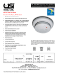
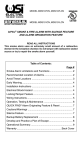
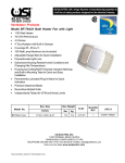
Model BFB-926 is used to hang ceiling fans and light fixtures between joists or structural members safely and securely.
• For new work installations
• Brace is adjustable from 16” to 24” joist spacing
• Includes non-metallic cable connector, mounting hardware and instructions
• High strength, hardened screws
• Knockouts in the bottom of box allows for easy entry and exiting with cables. Entering cable from bottom of box protects
wiring from damage by other finish construction trades.
INSTRUCTION SHEET
Only use the hardware supplied to mount outlet box and fan/fixture bracket.
Wiring must meet local and national codes.
BFB-926
BATH FAN
BOX WITH
BRACE
USI’s new construction brace and outlet box combination are CSA Listed for
ceiling fans (with or without accessories) and lighting fixtures:
Fan: 16” - 70 lbs. / >16” - 35 lbs. Fixture: 16” - 110 lbs. / >16” - 50 lbs.
CAUTION
Use care in installation to avoid knots in the wood, truss plates on trusses, as
well as electrical wires, plumbing, heating ducts and gas lines.
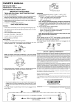
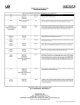
STEP 1. Slide the clamping bar into inner brace and then slide the outer
brace over the inner brace as shown below.
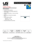
STEP 3. Expand the brace to fit between the structure members. Positioning
flanges, provide quick and accurate mounting of the brace with no guesswork
or measurements in 1/2” sheetrock applications.
Locating marks on the positioning flanges make positioning brace on center
lines easy. Break-off tabs provide quick positioning for 3/4” and 1” sheetrock
applications.
Secure with four #10 - 16 x 1” long sheet metal screws provided.
STEP 4. Slide the box to the desired position and tighten the two #12 - 24 x
3
/4” long screws in the bottom of the box securely.
STEP 2. Assemble outlet box to clamping bar by inserting two #12 - 24 x 3/4”
long screws through the two outside 1/4” diameter holes in the bottom of the
box. Thread these screws loosely into the two tapped holes in the clamping
bar as shown below.
0
NOTE: The box should be positioned under the outer bar for best results.
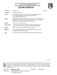
STEP 5. Remove the desired round knockout and install the non-metallic
cable connector (included) from inside the box into the round knockout
opening.
STEP 6. Push the cable through the connector.
STEP 7. Mount the fan bracket or light fixture bracket using two long #10 - 32
screws provided.
WARNING: The fan mounting screws and box mounting screws furnished
with the USI BFB-926 box must be used.
STEP 8. Follow the fan or fixture manufacturer’s wiring instructions.
ONE YEAR LIMITED WARRANTY
USI ELECTRIC, INC. ("USI") warrants your USI product to be free from defects in material and workmanship for a period of twelve (12) months from
the date of purchase. This warranty applies only to the original consumer purchaser and only to products used in normal residential use and service. If this
product is found to be defective, USI's only obligation, and your exclusive remedy, is the repair or replacement of the product, at USI's discretion, provided that
the product has not been damaged through misuse, abuse, accident, modifications, alteration, neglect or mishandling. This Warranty shall not apply to any
product which is found to have been improperly installed, set-up, or used in any way not in accordance with the instructions supplied with the product. This
Warranty shall not apply to any lamps or bulbs used in the product or to any damage which may be caused by such lamps or bulbs. For repair or replacement,
contact the following address: USI ELECTRIC, INC. at 11407 Cronhill Drive, Suite A, Owings Mills, Maryland 21117, during normal working hours. Provide the
Model Number of the product, date of installation and state the nature of the difficulty being experienced. Any and all product returns must be approved by the
above shown address whereby a return authorization number will be issued. Freight must be prepaid to this destination. No COD shipments are accepted.
To ensure safe operation:
•
Be sure unit is correctly installed and wired by a qualified installer in accordance with the instructions and applicable NEC or equivalent codes.
•
Be sure operating instructions are followed and that moving and heating parts are kept clean and free from obstructions.
•
Any warranties granted or liabilities assumed hereunder will not apply to goods that have been damaged in transit, altered, repaired, installed or operated
otherwise than in conformity with the above requirements for safe operation.
USI DOES NOT WARRANT AND SPECIFICALLY DISCLAIMS ANY WARRANTY, WHETHER EXPRESS OR IMPLIED, OF FITNESS FOR A PARTICULAR
PURPOSE, OTHER THAN THE WARRANTY CONTAINED HEREIN. NO IMPLIED WARRANTY ON THIS PRODUCT, CREATED BY STATE LAW, SHALL
EXTEND BEYOND THE TERM OF THIS WARRANTY UNLESS SUCH LAW OTHERWISE PROVIDES. USI SPECIFICALLY DISCLAIMS ANY LIABILITY
AND SHALL NOT BE LIABLE FOR ANY CONSEQUENTIAL OR INCIDENTAL LOSS OR DAMAGE, INCLUDING, BUT NOT LIMITED TO, DAMAGES TO
ANY EQUIPMENT WITH WHICH THIS PRODUCT IS USED.
Visit Us on the Web! www.usielectric.com.
288-3432-00B
11407 Cronhill Drive, Suite A
Owings Mills, Maryland 21117 USA
©2009, UNIVERSAL SECURITY INSTRUMENTS , INC. Rev. 2010
Printed in China