1
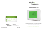
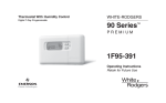
Universal
Digital 7 Day
Programmable
Comfort-Set®
90 Series
TM
P R E M I U M
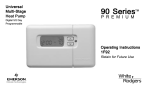
Model 975
Installation and Operating
Instructions
Retain for Future Use
Easy, Menu-Driven Set-Up
and Programming
1 2
3
4
5
6
7
8
9
10
11
12
Premium options
to customize the thermostat
to fit your application.
17
16
15
14 13
INTRODUCTION
Thank you for purchasing
your new Model 975 thermostat. White-Rodgers has been
producing energy saving
controls for over 60 years.
We have been designing and
producing the Comfort-Set
family of electronic programmable thermostats since
1982. Model 975 is the third
generation of the electronic
programmable family. We
believe you will find that
Model 975 is the most user
friendly and technologically
advanced thermostat available
today.
You will find information
about thermostat buttons and
display in the component
section beginning on page 2.
Installation instructions begin
on page 4.
Instructions for optional
thermostat configuration
begin on page 23. Programming information begins on
page 26. Descriptions of the
thermostat’s features begin on
page 32.
We have also added thumb
tabs to help you find sections
of the manual.
1
Introduction
Orientation
Installation
Configuration
Programming
Features
Index
ORIENTATION
THE THERMOSTAT BUTTONS
See inside front cover for illustration
showing button locations.
1 (Blue arrow) Lowers temperature
setting (45°F or 7°C minimum)
2 (Red arrow) Raises temperature
setting (99°F or 37°C maximum)
3 The yellow indicator glows when
the system is operating.
7 Used to adjust the time backward, or
to select the previous menu item.
14 Used to set the filter change-out
time, or to set the filter change timer.
8 Used to adjust the time forward, or
to select the next menu item.
15 Sets the system mode (HEATing,
OFF, COOLing, or AUTOmatic
changeover).
9 Used with TIME FWD /TIME
BACK to set the current day.
10 Used to advance operation to the
next program period.
4 This button (on top of the cover)
lights the display.
11 Used to manually override
programming to hold at a selected
temperature.
5 Used to initiate or review thermostat
programming.
12 Used to enter and configure the
VACATION mode.
6 Used with TIME FWD /TIME
BACK to set the clock.
13 Selects fan operation (see The
Display 21 ). This button is also used to
program the fan to run continuously
during a program period.
2
16 Used to adjust the clock one hour
forward or back.
17 Used to start or return to program
operation.
THE DISPLAY
18 Displays system mode (HEA
HEA
T , OFF
HEAT
OFF,
COOL
O , HOLD
CA).
COOL, AUT
UTO
HOLD, or VACA
During programming displays the time
MOR, DAY, EVE, NHT
period (MOR,
NHT) being
programmed.. In the configuration
menu, the menu item name is shown,
PR
GM MODE
MODE,
one word at a time (PR
PRGM
EMR
EMR, COOL FAN DELA OFF
OFF, etc.).
19 CHECK BATTERY appears when
the “AA” alkaline batteries are weak and
should be replaced. BATTERY appears
when the thermostat is running on
AT
STA
battery power only. CHECK ST
appears when the thermostat detects
certain problems within itself. CHECK
SYSTEM appears when the thermostat
detects certain problems in the heating
system.
20 Indicates the length of time
remaining in a temporary hold
condition. Also indicates the length of
time remaining in VACATION mode.
21 Displays FAN ON when the fan is
operating continuously. Displays FAN
AUT
O when the fan cycles with the
UTO
heating or cooling system.
22 Displays the setpoint temperature.
23 Alternately displays room
temperature and time of day.
18
19
21
20
CHECK BATTERY
CHECK BATTERY
STAT SYSTEM
HRS
HRS
FAN AUTO
HEAT
°F
24
23
AM
MON TUE WED THU FRI SAT SUN
22
Figure 1. The Display
3
Orientation
PRG
FAN ON
HEAT
°F
AM
MON TUE WED THU FRI SAT SUN
24 Shows the current day of the week.
When programming, shows the day(s)
being programmed.
21
18
25
25 The word HEA
T or COOL will
HEAT
appear above or below the setpoint if
area 18 is needed to display other
information.
INSTALLATION
DESCRIPTION
This White-Rodgers Automatic
Setback Digital Thermostat uses
microcomputer technology to
provide precise time and
temperature control. This
thermostat offers the flexibility
to design heating and cooling
programs that fit personal needs.
This thermostat is adaptable to
most 24 Volt residential forced
air, hydronic (hot water or
steam), millivolt, electric heat,
zone and single-stage heat pump
systems.
Standard Systems:
Fuel: gas, oil, electric.
Operating Ambient Temperature:
32° to 110°F (0° to 43°C)
SPECIFICATIONS
Model 975:
7 Day programming
ELECTRICAL DATA
Electrical Rating:
17 to 30 VAC, 50/60 Hz
0.05 to 1.5 Amps
1.5 Amps maximum total load (all
terminals combined)
Type: Heating/Cooling, Heat
Only, Hot Water or Steam
Systems, Single Stage
Compressor Heat Pump
THERMAL DATA
Setpoint Temperature Range:
45° to 99°F (7° to 37°C)
4
Operating Humidity Range:
90% non-condensing max.
Shipping Temperature Range:
-4° to 131°F (-20° to 55°C)
PRECAUTIONS
! WARNING
▲
! CAUTION
▲
Do not short out terminals
on gas valve or primary
control to test. Short or
incorrect wiring will damage
thermostat and could cause
personal injury and/or
property damage.
To prevent electrical shock
and/or equipment damage,
disconnect electric power to
system at main fuse or
circuit breaker box until
installation is complete.
Do not use on circuits
exceeding specified voltage.
Higher voltage will damage
thermostat and could cause
shock or fire hazard.
NOTE
Thermostat installation
and all components of the
system shall conform to
Class II circuits per the NEC
code.
Read all instructions
thoroughly before beginning
installation.
This thermostat is intended for use
with a low voltage system. Do not
use directly on a line voltage system
unless an isolation relay/transformer
is installed.
5
Installation
Do not exceed ratings shown in the
Specifications section, preceding
page. If in doubt about the electrical
ratings of your heating/cooling
system, have it inspected by a
qualified heating and air conditioning contractor or licensed electrician.
All wiring must conform to local
and national electrical codes and
ordinances.
This control is a precision instrument, and should be handled
carefully. Rough handling or
distorting components could cause
the control to malfunction.
INSTALLATION
ATTENTION!
This product does not contain
mercury. However, this product
may replace a unit which contains
mercury.
Do not open mercury cells. If a
cell becomes damaged, do not touch
any spilled mercury. Wearing nonabsorbent gloves, take up the spilled
mercury with sand or other
absorbent material and place into a
container which can be sealed. If a
cell becomes damaged, the unit
should be discarded.
Mercury must not be discarded in
household trash. When the unit this
product is replacing is to be
discarded, place in a suitable
container and return to WhiteRodgers at 2895 Harrison Street,
Batesville, AR 72501 for proper
disposal.
REMOVE
OLD THERMOSTAT
Shut off electricity at main fuse or
circuit breaker box until installation
is complete AND the jumper leads
on the back of the new thermostat
are configured properly.
Remove the front cover of the old
thermostat. With wires still attached,
remove wall plate from the wall.
Identify each wire attached to the
thermostat using one of the labels
enclosed with the new thermostat.
Disconnect the wires from the old
thermostat one at a time. DO NOT
let the wires fall back into the wall.
Install the new thermostat using the
following procedures.
6
ATTACH BASE TO WALL
Remove packing material from the
thermostat. Place fingers of one
hand on the center top and bottom
portion of the thermostat. Grasp the
base in the other hand on top and
bottom center and gently pull
straight out. Forcing or prying on
the thermostat will cause damage to
the unit.
Place the base over the hole in the
wall where the wires come out and
mark mounting hole locations using
the base as a template. Drill 3/16”
pilot holes, and install screw
anchors in the wall.
Run wires through hole in base and
attach base to wall (see fig. 1).
4
Insert the wires into the terminals on
the base using the appropriate
wiring diagram and tighten the
terminal screws.
3
2
1
CONFIGURING
AND PROGRAMMING
S1 S2 S3
MV W RH RC G Y O B
1
6
Before the power is turned on, the
thermostat must be configured to
operate properly with the system.
See the CONFIGURATION section
of this manual.
This thermostat can be programmed
for automatic temperature control.
Figure 1. Thermostat base and terminals
Refer to Operating Instructions for 1 Mounting screws
programming.
2 Pull wires through this opening
3 Insert wires into terminal holes, then tighten screws
4 Screw anchors
7
Installation
WIRING DIAGRAMS
All wiring diagrams are for typical systems only. Refer to equipment manufacturers’ instructions for specific system
wiring information.
1
3
2
H
MV
6
Y
G
W
O
B
RC
RH
W
MV W RH RC G
E
J
O
B
6
K
I
M
2 From 24 VAC transformer
See page 10 for letter identification.
Y
L
1 From heating system
3 Red jumper wire (provided)
RH
NOTE: Ensure that RED RH/RC jumper wire (provided with thermostat) is
connected between thermostat’s RH and RC terminals for proper
operation with this system.
Figure 2. Typical wiring diagram for heating only, two-wire, single transformer system
8
1
3
2
4
5
H
MV
6
Y
G
W
C
D
E
O
B
RC
RH
4 Red jumper wire (provided)
5 Red jumper wire (provided)
G
Y
Y
O
B
6
L
K
I
M
1 From heating system
3 Red jumper wire (provided)
RH
MV W RH RC G
J
2 From 24 VAC transformer
W
NOTE: Ensure that RED RH/RC jumper wire (provided with thermostat) is
connected between thermostat’s RH and RC terminals for proper
operation with this system.
NOTE: For three-wire heat only system, connect terminals G , W , and RH
RH.
For cool only system, connect terminals Y , G , and RH
RH.
See page 10 for letter identification.
Figure 3. Typical wiring diagram for heat only, cool only, & heat/cool single transformer system
9
Installation
WIRING DIAGRAMS
1
MV
6
Y
G
W
O
B
RC
RH
MV
RH
MV W RH RC G
A
Y
O
B
6
NOTE: Thermostat must have batteries installed.
1 From millivolt system
Figure 4. Typical wiring diagram for millivolt system
A Millivolt System
B Zone Valve
G Changeover Relay Energized in
Heating (Single Stage Heat
Pump System)
L Hot Side
M Neutral Side
C Cooling System
H Jumper Wire
N HEATING TRANSFORMER
D Fan Relay
I TRANSFORMER
O COOLING TRANSFORMER
E Heating System
J 24 VAC Side
P Jumper Wire (field-installed)
F Changeover Relay Energized in
K 120 VAC Side
Cooling (Single Stage Heat
Pump System)
10
1
MV
A
6
Y
G
C
D
W
O
B
RC
RH
MV
3
2
RH
RC
MV W RH RC G
G
Y
Y
O
B
L
J
K
I
M
1 From heating system
2 From 24 VAC transformer
NOTE: Thermostat must have batteries installed.
3 From fan relay
4 From cooling system
See page 10 for letter identification.
Figure 5. Typical wiring diagram for two-wire millivolt heating & three-wire cooling system
11
Installation
4
6
WIRING DIAGRAMS
1
3
2
1
H
MV
6
Y
6
4 5
1
2
B
G
W
O
B
RC
RH
3 Red jumper wire (provided)
Y
O
B
6
L
K
I
M
1 From zone valve
(through zone valve)
6
RH
MV W RH RC G
J
2 From 24 VAC transformer
W
NOTE: Thermostat must have batteries installed.
NOTE: Ensure that RED RH/RC jumper wire (provided with thermostat) is
connected between thermostat’s RH and RC terminals for proper
operation with this system.
See page 10 for letter identification.
Figure 6. Typical wiring diagram for heat only, three-wire, zone valve system
12
1
MV
6
Y
G
W
O
B
RC
3
2
RH
W
RH
R
C
5
4
G
Y
Y
O
L
C
D
MV W RH RC G
E
J
K
N
M
L
J
1 From heating system
K
O
M
2 From 24 VAC heating transformer
3 From 24 VAC cooling transformer
4 From fan relay
5 From cooling system
See page 10 for letter identification.
Figure 7. Typical wiring diagram for heat/cool, five-wire, two-transformer system
13
Installation
B
6
WIRING DIAGRAMS
2
1
P
MV
6
Y
G
C
D
3
4
5
H
W
O
B
F
G
RC
RH
RC
MV W RH RC G
G
Y
Y
O
B
6
L
J
K
I
M
1 From heating system
2 Red jumper wire (provided)
3 Field-installed jumper wire
4 From fan relay
NOTE: Ensure that RED RH/RC jumper wire (provided with thermostat) is
connected between thermostat’s RH and RC terminals for proper
operation with this system.
5 From cooling system
See page 10 for letter identification.
Figure 8. Typical wiring diagram for single stage heat pump, four-wire, single transformer system
14
CONFIGURATION
JUMPERS
Before turning power on to the
system, the jumpers on the back of
the thermostat must be configured to
operate correctly with the system
equipment.
This thermostat is configured from
the factory to operate a standard
fossil fuel (gas, oil, etc.), forced hot
air system with a single stage air
conditioning compressor and fan.
This is the correct configuration for
any system that DOES NOT require
the thermostat to energize the fan on
a call for heat.
instantly on a call for heat. If you
are unsure if the system requires the
thermostat to control the fan, contact
a qualified heating and air conditioning service person.
A remote sensor can be used with
this thermostat. To use a remote
sensor, jumper W922 must be
clipped (see fig. 9) and the REMT
SEN option in the configuration
menu must be set to ON.
1
1 Clip for remote sense
2
W914
W922
2 3-pin connector
3 Clip for electric heat
If you have an electric heat or other
system that REQUIRES the
thermostat to control the fan, find
and cut the jumper lead labelled
W914 (see fig. 9). This will allow
the thermostat to energize the fan
Figure 9. Jumper locations
15
Installation
3
CONFIGURATION MENU
Step
Press Button(s)
Displayed (Factory Default)
Press
or
to select:
COMMENTS
Selects EMR option ON or OFF
1
TIME
FWD
EMR
(ON)
OFF
2
TIME
FWD
SET CYCL HEAT
(05)
02 - 40
Adjusts heat anticipation value (2 through 40)
3
TIME
FWD
SET CYCL COOL
(14)
09 - 40
Adjusts cool anticipation value (9 through 40)
4
TIME
FWD
COOL FAN DELA OFF
(01)
01 - 127
Adjusts cool fan-off delay (1 through 127 sec.)
5
TIME
FWD
COOL FAN DELA ON
(04)
01 - 05
Adjusts cool fan-on delay (1 through 5 sec.)
6
TIME
FWD
COMP LOCK
(ON)
OFF
7
TIME
FWD
SYSTEM
(HEAT-OFF-COOL-AUTO)
HEAT-OFF,
COOL-OFF,
HEAT-OFF-COOL
16
Selects compressor lockout ON or OFF (see NOTE)
Selects system switch choices for heat only,
cool only, heat/cool or automatic changeover
Adjusts temperature display higher or lower
8
TIME
FWD
0˚F
(0)
5 LO to
5 HI
9
TIME
FWD
(˚F)
C
10
TIME
FWD
BEEP
(ON)
OFF
Turns beeper ON or OFF
11
TIME
FWD
REMT SEN
(OFF)
ON
Selects remote sensor OFF or ON
12
TIME
FWD
PART LOCK
(OFF)
ON
Selects partial keypad lockout OFF or ON
13
TIME
FWD
LOCK
(OFF)
ON
Selects total keypad lockout OFF or ON
14
PROGRAM
Adjusts temperature display to ˚F or ˚C
Returns to normal operation
RUN
17
Installation
CONFIGURATION
INSTALLER
CONFIGURATION
The configuration settings can be
changed at any time to meet system
or personal requirements.
Press PROGRAM RUN to make
certain the thermostat is in the run
program mode, then press TIME
FWD and TIME BACK at the same
time to enter the configuration
menu. The display will change to
show the first option on the
configuration menu. The chart on
page 16 briefly describes each
option on the menu. Following are
more detailed descriptions of the
options recommended for selection
by the installer. For more detailed
descriptions of other options, refer
to the Operating Instructions. Make
selections for each option as
required.
When the option is set to your
choice, press TIME FWD to
change the display to the next step.
To return to a previous option, press
TIME BACK .
To exit the configuration menu at
any time, press PROGRAM .
SELECTABLE ENERGY
MANAGEMENT RECOVERY
Energy Management Recovery
(EMR) causes the thermostat to start
operating the system early in order
to make the building temperature
reach the programmed setpoint at
the programmed time. In heating,
the thermostat will start 5 minutes
early for every °F difference
between the room temperature and
18
the next programmed temperature.
In cooling the thermostat uses 15
minutes per °F.
The maximum time the thermostat
can start early in heating is 75
minutes. The maximum time the
thermostat can start early in cooling
is 3 hours and 45 minutes. Cooling
can start earlier because it takes
longer to reach temperature.
ADJUSTABLE
ANTICIPATION
This option allows the cycle times in
heating and cooling to be increased
or decreased. The factory set values
can be adjusted higher for longer
cycles or lower for shorter cycles.
The adjustment range for HEATING
is from 2 to 40. The factory preset is
5. The adjustment range for
PROGRAMMABLE COOL
FAN-ON AND FAN-OFF
DELAY
COOLING is from 9 to 40. The
factory preset is 14. The recommended initial setting for hydronic
systems is 35.
This option allows a selection of a
fan-on delay of 1 to 5 seconds on a
call for cool and 1 to 127 seconds of
fan-off delay after the thermostat
has satisfied the call for cool.
A short delay to allow the A-coil to
cool off before the fan turns on may
The cooling will not go below 9
because compressors require a
longer cycle.
The chart below shows how this
adjustment range affects thermostat
performance.
be preferred. This also allows the
compressor and the fan to come on
at slightly different times, which
allows full power to the compressor
on start up.
The fan off delay allows the fan to
continue running after the compressor has shut off. This distributes the
cooling that would otherwise stay
trapped in the air conditioning coils
through the ducts. Ideally the timing
HEATING
COOLING
Anticipation Value
Cycle Length
Differential Temperature Cycle Length Differential Temperature
2–8
Shorter
0.4–0.6 F (0.2–0.3 C)
N/A
N/A
9–20
Longer
0.6–1.0 F (0.3–0.6 C)
Shorter
0.6–1.0 F (0.3–0.6 C)
21–40
Hydronic
1.0–1.6 F (0.6–0.9 C)
Longer
1.0–1.6 F (0.6–0.9 C)
These numbers are approximate and represent operation with a typical system. Actual temperature differentials and
run times may vary widely based on your building and equipment, as well as outdoor temperature conditions.
19
Installation
CONFIGURATION
would be set so the fan shuts off just
as the cool air is exhausted. If this
timing is set too long the fan may
begin blowing warm air before it
shuts off. Shortening the fan-off
delay will prevent this.
COMPRESSOR LOCKOUT
This thermostat is designed to
protect the system against premature
compressor failure by “locking out”
the compressor for at least five
minutes after each cycle. When the
thermostat is in compressor lockout,
the word COOL will flash on the
display. During this period, the
compressor will not be energized.
If the system has short-cycle
protection, this feature can be
disabled.
Lockout Bypass Option
FOR QUALIFIED SERVICE
TECHNICIANS’ USE ONLY.
HOMEOWNERS SHOULD
NOT USE THIS FEATURE
DUE TO POSSIBILITY OF
EQUIPMENT OR PROPERTY
DAMAGE, OR PERSONAL
INJURY.
DISABLING HEAT, COOL
OR AUTO MODES
The automatic changeover feature of
this thermostat can be disabled
(automatic changeover allows the
thermostat to switch between
heating and cooling to maintain
temperature). If this thermostat is
controlling a heating-only or
cooling-only system, the heat, cool,
or auto modes can be disabled.
20
COMPRESSOR SHORT TERM
CYCLE PROTECTION
This thermostat has a built-in
short term (5-minute) time delay.
During this 5-minute period, the
thermostat will lock out the
compressor to allow head
pressure to stabilize. To override
this feature for one cycle while
testing thermostat operation,
press SET TIME and SET DAY
buttons at the same time.
OPTIONAL REMOTE
TEMPERATURE SENSE
An optional remote sensor (part #
F145-1328) can be attached to this
thermostat and may be wired as far
away as 200 feet. The thermostat
will use the temperature in the
remote location as its room
CHECK THERMOSTAT OPERATION
temperature display.
After the thermostat is installed and
configured, do the following to
ensure proper operation.
This is an excellent feature if the
thermostat is in a poor location for
sensing temperature or the thermostat is in a separate room to prevent
tampering.
FAN OPERATION
If your system does not have a G
terminal connection, skip to
“Heating System” section.
NOTE
The remote sense feature will not
work if the system does not
provide 24V to the thermostat
(example: millivolt heating-only
systems or 3-wire zone valves).
To use a remote sensor, jumper
W922 must be clipped (see figure 9)
and the REMT SEN option in the
configuration menu must be set to
ON.
1. Turn power on to the system.
2. Press FAN until FAN ON is
displayed. The fan should begin
to operate.
3. Press FAN until FAN AUTO
is displayed. The fan should stop
operating.
21
Installation
HEATING SYSTEM
1. Press SYSTEM until HEAT is
displayed. If the heating system
has a standing pilot, ensure that it
is lit.
to adjust thermostat
2. Press
setting above room temperature.
The heating system should begin
to operate.
3. Press
to adjust temperature
below room temperature. The
heating system should stop
operating.
CHECK THERMOSTAT OPERATION
COOLING SYSTEM
RESETTING THERMOSTAT
!
WARNING
To prevent compressor and/
or property damage, if the
outdoor temperature is below
50°F (10°C), DO NOT
operate the cooling system.
1. Press SYSTEM until COOL is
displayed.
to adjust thermostat
2. Press
setting below room temperature.
The fan should come on (after
the fan-on delay time, if any),
followed by cold air circulation.
3. Press
to adjust temperature
setting above room temperature.
The cooling system should stop
operating, and the fan should
stop running (after the fan-off
delay time, if any).
The thermostat can be reset back to
factory default programs and
configuration options. Removing
power from the thermostat will not
reset it to the default settings. Before
resetting the thermostat, you may
want to make note of the previously
selected configuration options and
programming.
To reset the thermostat, press and
release PROGRAM RUN , then
press the FAN , TIME BACK and
buttons at the same time. This
will reset the thermostat to factory
default programs and configuration.
The display will momentarily go
blank, then all segments on the
display will momentarily be shown.
The thermostat will then go into the
22
HOLD mode and will maintain
factory preset temperatures.
CONFIGURATION
The configuration menus allow you
to set certain thermostat operating
characteristics to your system or
personal requirements.
To enter the User Configuration menu,
press PROGRAM RUN to make sure
the thermostat is in the run program
mode, then press TIME FWD and
TIME BACK at the same time to enter
the configuration menu. The display will
show the first item in the configuration
menu.
The following chart (pages 24 & 25)
describes each item on the menu and the
applicable model(s). Set these according
to your personal preference. To exit the
menu, press PROGRAM RUN . To
return to the menu at any time press
PROGRAM RUN , then press TIME
FWD and TIME BACK at the same
time. While in the configuration menu,
if you do not press any buttons for two
minutes, the thermostat will revert to
normal operation.
23
Configuration
You should contact a qualified service
person to change items that are
indicated “Recommend Installer
Setting”.
Operator may change shaded options if
desired. We recommend that other
options be set by the installer.
CONFIGURATION MENU
Step
Press Button(s)
Displayed (Factory Default)
Press
or
OFF
to select:
COMMENTS
Selects EMR option ON or OFF
1
TIME
FWD
EMR
(ON)
2
TIME
FWD
SET CYCL HEAT
Recommend installer setting
3
TIME
FWD
SET CYCL COOL
Recommend installer setting
4
TIME
FWD
COOL FAN DELA OFF
Recommend installer setting
5
TIME
FWD
COOL FAN DELA ON
Recommend installer setting
6
TIME
FWD
COMP LOCK
Recommend installer setting
7
TIME
FWD
SYSTEM
Recommend installer setting
24
8
TIME
FWD
0˚F
(0)
5 LO to
5 HI
9
TIME
FWD
(˚F)
˚C
10
TIME
FWD
BEEP
(ON)
OFF
11
TIME
FWD
REMT SEN
12
TIME
FWD
13
TIME
FWD
14
PROGRAM
Adjusts temperature display higher or lower
Adjusts temperature display to ˚F or ˚C
Turns beeper ON or OFF
Recommend installer setting
PART LOCK
(OFF)
ON
Selects partial keypad lockout OFF or ON
LOCK
(OFF)
ON
Selects total keypad lockout OFF or ON
Returns to normal operation
RUN
25
Configuration
PROGRAMMING
MANUAL OPERATION
Your Comfort-Set 90 thermostat can
be used to control temperature
manually (without programming).
For manual operation, press SYSTEM
to select HEAT or COOL
COOL, then
press PROGRAM HOLD . Use
or
to set the temperature as desired.
PROGRAMMED OPERATION
Planning Your Program
The sample schedule (pages 28 &
29) shows the factory installed
programs for heating and cooling.
The heating and cooling programs
are separate, and must be programmed individually. To use the
factory program, set the clock and
press PROGRAM RUN with the
Heat,
thermostat SYSTEM set to Heat
Cool
Cool, or Auto
Auto.
Fill out the blank schedules (pages
30 & 31) with the time and
temperatures you want in your
program. Fill in every space for your
program.
The same temperature can be
repeated more than once if you do
not want the temperature to change
over several time periods.
Entering Your Program
Clock:
To Set the Clock
1. Press PROGRAM RUN .
2. Press SET TIME . The display
will show the hour. Use TIME
FWD or TIME BACK to set to the
current hour and AM/PM designation.
26
3. Press SET TIME again. The
display will show minutes. Use
TIME FWD or TIME BACK to set
to the current minutes.
4. Press PROGRAM RUN .
To Set the Day
Day:
5. Press SET DAY . The display
will indicate a day of the week. Use
TIME FWD or TIME BACK to set
to the current day of the week.
6. Press PROGRAM RUN .
To Set the Program
Program:
SYSTEM
to select HEAT
7. Press
(for heating program) or COOL (for
cooling program).
8. Press PROGRAM VIEW one
time. The display will show MOR
and the settings for time and
temperature.
9. If you program Monday the first
time you press PROGRAM VIEW
it will be copied to the rest of the
week. To program the other days of
the week press ADV. /DAY to until
you reach the day you wish to
change and follow Steps 10, 11 &
12. You can also copy the program
from one day to another. To copy,
press HOLD /COPY. The display will
show COPY, and all the other days
of week will be flashing. Press
HOLD /COPY again to copy the day
in to the rest of the week or press
TIME FWD or TIME BACK until
you reach the day you want to copy
to and press HOLD /COPY.
10.Press TIME FWD or TIME
BACK to set the time on the display
as selected in your HEATING or
COOLING Schedule. Be sure to
check the AM or PM on the display.
11.Press the red
or blue
button to adjust the temperature to match your schedule. If you
want the fan ON continuously
during this period, press FAN .
you are satisfied that your program
matches your schedule, press
PROGRAM RUN . Programming
is now complete for this mode and
your program is running.
14.To program the other mode,
repeat the procedure from step 6.
12.Press PROGRAM VIEW one
time. MOR on the display will
change to DAY. Repeat steps 10
and 11 to enter time and temperature
for this period.
13.Press PROGRAM VIEW to
continue through the entire
schedule, entering time and
temperature for each period. When
27
Programming
7 Day Sample HEAT Program Schedule
(Shows factory programming)
1
1
2
3
4
5
6
2
3
4
5
6
5
6
5
6
5
6
MON
6:00 AM
70°F (21°C)
8:00 AM
62°F (16°C)
5:00 PM
70°F (21°C)
10:00 PM
62°F (16°C)
TUE
6:00 AM
70°F (21°C)
8:00 AM
62°F (16°C)
5:00 PM
70°F (21°C)
10:00 PM
62°F (16°C)
WED
6:00 AM
70°F (21°C)
8:00 AM
62°F (16°C)
5:00 PM
70°F (21°C)
10:00 PM
62°F (16°C)
THU
6:00 AM
70°F (21°C)
8:00 AM
62°F (16°C)
5:00 PM
70°F (21°C)
10:00 PM
62°F (16°C)
FRI
6:00 AM
70°F (21°C)
8:00 AM
62°F (16°C)
5:00 PM
70°F (21°C)
10:00 PM
62°F (16°C)
SAT
6:00 AM
70°F (21°C)
8:00 AM
62°F (16°C)
5:00 PM
70°F (21°C)
10:00 PM
62°F (16°C)
SUN
6:00 AM
70°F (21°C)
8:00 AM
62°F (16°C)
5:00 PM
70°F (21°C)
10:00 PM
62°F (16°C)
Morning (MOR)
Day (DAY)
Evening (EVE)
Night (NHT)
Start Time
Temperature
28
7 Day Sample COOL Program Schedule
(Shows factory programming)
1
MON
1
2
3
4
5
6
2
3
4
5
6
5
6
5
6
5
6
6:00 AM
78°F (25°C)
8:00 AM
85°F (29°C)
5:00 PM
78°F (25°C)
10:00 PM
82°F (27°C)
TUE
6:00 AM
78°F (25°C)
8:00 AM
85°F (29°C)
5:00 PM
78°F (25°C)
10:00 PM
82°F (27°C)
WED
6:00 AM
78°F (25°C)
8:00 AM
85°F (29°C)
5:00 PM
78°F (25°C)
10:00 PM
82°F (27°C)
THU
6:00 AM
78°F (25°C)
8:00 AM
85°F (29°C)
5:00 PM
78°F (25°C)
10:00 PM
82°F (27°C)
FRI
6:00 AM
78°F (25°C)
8:00 AM
85°F (29°C)
5:00 PM
78°F (25°C)
10:00 PM
82°F (27°C)
SAT
6:00 AM
78°F (25°C)
8:00 AM
85°F (29°C)
5:00 PM
78°F (25°C)
10:00 PM
82°F (27°C)
SUN
6:00 AM
78°F (25°C)
8:00 AM
85°F (29°C)
5:00 PM
78°F (25°C)
10:00 PM
82°F (27°C)
Morning (MOR)
Day (DAY)
Evening (EVE)
Night (NHT)
Start Time
Temperature
29
Programming
7 Day Personal HEAT
Program Schedule
1
5
2
6
5
3
6
5
MON
TUE
WED
THU
FRI
SAT
SUN
1
2
3
4
5
6
Morning (MOR)
Day (DAY)
Evening (EVE)
Night (NHT)
Start Time
Temperature
30
4
6
5
6
7 Day Personal COOL
Program Schedule
1
5
2
6
5
3
6
5
4
6
MON
TUE
WED
THU
FRI
SAT
SUN
1
2
3
4
5
6
Morning (MOR)
Day (DAY)
Evening (EVE)
Night (NHT)
Start Time
Temperature
31
Programming
5
6
FEATURES
Large Lighted Liquid
Crystal Display (LCD).
The large numbers and letters on
your LCD screen make it easy to
see. In low light conditions, press
the button on top of the thermostat
and the display will light up for
three seconds. For ten minutes after
pressing the light button, pressing
any other button will light the
display for ten seconds. The display
light uses power from the 3 “AA”
alkaline batteries installed. Excessive use of the display light will
reduce battery life.
The thermostat display alternately
shows the current time and the
current temperature on the left side.
The display also shows the
temperature you have programmed
or set on the right side of your
screen.
Setpoint Range
45-99°F (7-37°C).
You may set your thermostat to any
temperature from 45° to 99°F. If you
prefer, you may configure the
thermostat to display Celsius. This
is covered in the CONFIGURATION section (page 25, step 9).
Selectable Energy
Management Recovery (EMR).
EMR causes the thermostat to start
operating the system early in order
to make the building temperature
reach your program setpoint at the
time you specify. In heating, the
thermostat will start 5 minutes early
for every 1°F difference between the
32
room temperature and the next
programmed temperature. In
cooling, the thermostat uses 15
minutes per °F.
EXAMPLE: If the temperature in
the room is 65°F and the thermostat
is programmed for 70°F at 7 AM,
the thermostat will start approximately 25 minutes early. The
difference between the room
temperature (65°F) and the setpoint
(70°F) is 5°. 5° X 5 minutes per °F
= 25 minutes. The setpoint on the
display will actually change to
display 70° about 25 minutes early.
The maximum time the thermostat
can start early in heating is 75
minutes. The maximum time the
thermostat can start early in cooling
is 3 hours and 45 minutes. Cooling
can start earlier because it takes
longer for cooling systems to reach
the desired temperature.
To select or deselect this feature,
refer to the CONFIGURATION
section (page 24, step 1).
Adjustable
Temperature Display.
The room temperature display can
be adjusted to read higher or lower
by following the configuration menu
and adjusting the temperature to a
higher or lower value. The thermostat is calibrated at the factory to
display a very accurate room
temperature, but due to various
conditions and/or personal preference, you may wish to adjust the
thermostat display higher or lower
(up to 5°F). For example, if the
thermostat displays a room
temperature of 70° but you want it
to display 73°, you can adjust it. To
adjust, refer to the CONFIGURATION section (page 25, step 8).
Factory Preprogrammed
Times and Temperatures.
This thermostat has been programmed at the factory. The chart in
the programming examples section
lists these factory settings. If the
times and temperatures are the same
as your schedule, you may simply
run the factory installed program by
pressing PROGRAM RUN .
Arm Chair Programming.
The thermostat uses 24 VAC power
supplied by the system for normal
operation. However, if the installed
“AA” batteries are providing
sufficient power, you can program
the thermostat away from the wall.
If the thermostat indicates low
battery power (CHECK BATTERY), refer to the Battery Back-up
feature (page 37).
Programmable Fan Control.
This feature allows you to have your
fan operate continuously through
one or more programmed time
periods. This is useful if you want to
have constant air circulation in your
location during a specific time
period. If you do not use this
feature, the fan will cycle normally
with the heating and cooling system.
Automatic Changeover.
If you have a heating/cooling
system, the thermostat can be set to
automatically switch the system
33
Features
from heating to cooling as needed.
To set your thermostat to this
operating mode, press SYSTEM
button until AUTO is displayed on
the screen.
Pressing the
and
buttons at the same time will change
the setpoint temperature displayed
to the setpoint of the other mode.
This will allow you to modify both
the HEAT and COOL setpoints to
accommodate a HOLD condition
while in Automatic Changeover
mode.
Air Filter
Change-Out Indicator.
This feature allows the thermostat to
display the words CHNG FLTR
(change filter) after a set time of fan
operation. This is a reminder to
change or clean your air filter. The
factory set interval for CHNG
FLTR to be displayed is 200 hours
of fan operation. This can be set
anywhere from 0 to 1950 hours in
25 hour increments. A selection of
00 will cancel this feature.
When CHNG FLTR is displayed,
you can clear it by pressing the
FILTER button. This resets the
timer and starts counting the hours
until the next filter change.
The following steps will allow you
to change the number of hours for
filter change-out.
1. If you see CHNG FLTR on the
display, press the FILTER button
once to reset the timer. If you do not
see CHNG FLTR proceed to step 2.
When the FILTER button is pressed
34
once, the display will show the
number of hours remaining before
CHNG FLTR indicator will
display.
2. Press the FILTER button. The
display will show SET FILTER
TIME and will show the number of
hours to filter change.
3. Press TIME FWD or TIME
BACK to change the time to your
requirements.
4. Press PROGRAM RUN to
return to the normal operating mode.
NOTE: If unsure what interval to
use between filter changes or
cleaning, contact the manufacturer
of your heating/cooling equipment.
Temporary Program Override.
Any time your program is running
and you would like to override it for
a specific amount of time, press
or
until the temperature you want is displayed. The
display will indicate HOLD, and the
number of hours remaining in the
hold period will be indicated with
the word HRS. To adjust the length
of time for the override, press
TIME FWD or TIME BACK .
HOLD TILL will be displayed as
well as the HOLD period expiration
time. Press TIME FWD or TIME
BACK buttons until you reach the
time you would like it to resume the
program. The TIME FWD or
TIME BACK buttons adjust the time
in 15 minute increments. This
programmed hold time has a 19
hour maximum and 15 minute
minimum. Beyond 19 hours you
may wish to use the vacation hold
feature (page 36). If you need to,
you can adjust the temperature up or
down.
Indefinite Program Hold.
If you want to operate the thermostat to keep a set temperature
without a program running, press
PROGRAM HOLD . The
or
buttons can be use to raise or
lower the temperature. The
thermostat will hold the set
temperature until you return to the
program by pressing PROGRAM
RUN .
Thermostat Startup
After Total Power Loss.
On installation, or when power is
restored after a total power loss to
the thermostat, your thermostat will
automatically maintain a heating
temperature of 62°F (16°C) and a
cooling temperature of 85°F (29°C).
A total loss of power will occur
when you lose 24 VAC power to the
thermostat, and you have no battery
backup. If this happens, the
thermostat display will go blank in
about one minute after power loss.
When power is restored, the
thermostat will automatically return
to the temperatures listed above. If
this happens, set the clock and day
of the week (use steps 1 through 6
from “Entering Your Program”,
page 26), then select HEAT, COOL
or AUTO using the SYSTEM . button,
and press PROGRAM RUN to
resume operation with your
previously set program.
35
Features
Daylight Savings Time Button.
One button adjustment allows you to
change your thermostat clock
between Standard Time and
Daylight Savings time. Simply push
the DAYLIGHT SAVINGS TIME
button to advance the time forward
one hour in the Spring. In the Fall,
press the DAYLIGHT SAVINGS
TIME button twice to fall back an
hour. If you push it three times in a
row (in less than 30 seconds) it will
return to the original time setting.
After clock adjustment, press
PROGRAM RUN to resume your
normal program.
Programmable Vacation Time/
Temperature Operation.
The VACATION button allows you
to program the thermostat to hold a
constant temperature for 1 to 29
days. At the end of the day and time
you select, the thermostat will return
to normal program operation.
To program the number of days,
press VACATION. VACA HOLD
TILL will be displayed. The display
will also show DAYS (flashing) and
the number 5. To change the number
of vacation days, press TIME FWD
or TIME BACK . Press
or
to set the temperature you
wish to maintain while away. While
still in the vacation mode, set the
time you want the program to
resume by pressing SET TIME
once. The current time will display.
Press TIME FWD to adjust the
time in 15 minute increments. You
may wish to select a few hours in
advance of your expected return to
allow time to reach the desired
36
temperature. Your thermostat is now
programmed to hold the temperature
you selected through your vacation
for HEAT, COOL, or AUTO.
After 20 seconds the display will
return to time/temperature alternation, and will display VACA.
Pressing VACATION again will
activate the vacation mode settings.
Pressing PROGRAM RUN cancels
this feature and begins running your
normal program.
Keypad Lockout.
This security feature allows you to
lock out the keypad to prevent
unauthorized tampering with the
program. Two levels of security are
available, Total Keypad Lockout or
Partial Keypad Lockout. Total
Keypad Lockout renders all buttons
inoperative. Partial Keypad Lockout
allows only the
or
to
operate for temporary temperature
overrides. It also limits the temperature to the maximum heating and
minimum cooling temperatures used
in your program. This is especially
useful in buildings where unscheduled events are common. Anyone
can change the temperature, but
only between the temperatures you
set and only for two hours or the
number of hours you specify if you
set up your Hold Till timing (see
Temporary Program Override (page
34). To select or deselect this
feature, refer to the CONFIGURATION section (page 25, steps 12 and
13).
Battery Back-Up.
Three “AA” alkaline batteries allow
the thermostat to maintain its
program in the event of a power
loss. They also operate the back
light for viewing the display in low
light conditions, and allow for
armchair programming.
CHECK BATTERY will be
displayed when the batteries are
low. To assure optimum performance, change batteries once a year
or when CHECK BATTERY is
displayed. When changing batteries,
always replace all three batteries
with new “AA” alkaline batteries
(for optimum performance, we
recommend Energizer® batteries). If
the batteries must be changed
frequently, it may indicate a
problem with the system. Contact
the heating/cooling system manufacturer or a service person. Remember
that excessive use of the display
light will reduce battery life.
System and
Thermostat Diagnostics.
The display will indicate CHECK
SYSTEM if the room temperature
does not rise within two hours of the
call for heat. After two hours the
thermostat will quit calling for heat
for one minute (this allows some
furnaces to reset) and call for heat
again. It will repeat this sequence
three times. If the temperature still
does not rise, it will continue to call
for heat. This normally indicates the
heating system is not working
correctly. You may wish to consult
your furnace manufacturer or
service person.
The display will indicate CHECK
STAT if one of the following occurs.
37
Features
• One of the buttons is stuck down
or in. Check buttons, make sure
nothing is pushing them in.
• The thermostat sensor is not
functioning. If using a remote
sensor, check connections, wiring
and power.
After checking the above, press
PROGRAM RUN to reset the
display. If this does not clear the
display, disconnect power and
remove the batteries for five
minutes.
If these checks fail to solve the
problem, the thermostat should be
replaced.
Compressor
Short-Cycle Protection.
Your thermostat is designed to
protect your system against
premature compressor failure by
“locking out” the compressor. This
ensures that the compressor will stay
off for at least five minutes on each
cycle. When the thermostat is in
compressor lock-out, the word
COOL will flash. During this
period, the compressor will not be
energized.
INDEX
Adjustable Temperature Display 33
Air Filter Change-out Indicator 34
Arm Chair Programming -------- 33
Automatic Changeover --------- 33
Battery Back-Up ------------------ 37
COMPONENTS ------------------- 2
Thermostat Buttons ------------ 2
Display --------------------------- 3
Compressor Short-Cycle
Protection -------------------------- 38
CONFIGURATION -------------- 23
Configuration Menu Chart ------ 24
Copy -------------------------------- 27
Daylight Savings Time Button -- 36
Energy Management Recovery - 32
Fan Control, Programmable ----- 33
Factory Preprogrammed --------- 33
FEATURES ----------------------- 32
INTRODUCTION ----------------- 1
Keypad Lockout ------------------ 36
Liquid Crystal Display ----------- 32
Operation
Manual -------------------------- 26
Programmed -------------------- 26
Program
Entering Your ------------------ 26
Indefinite Hold ----------------- 35
Planning Your ------------------ 26
Temporary Override ----------- 34
INSTALLATION ------------------ 4
ORIENTATION -------------------- 2
PROGRAMMING --------------- 26
Schedule
Sample Programs -------------- 28
Personal Programs ------------- 30
Set
Clock ---------------------------- 26
Day ------------------------------ 26
Program ------------------------- 26
Setpoint Range -------------------- 32
System and Thermostat
Diagnosis ----------------------- 37
Thermostat Startup After Total
Power Loss --------------------- 35
Vacation ---------------------------- 36
37-6438A
0225
Index
NOTES
The Emerson logo is a
trademark and service mark
of Emerson Electric Co.
White-Rodgers is a division
of Emerson Electric Co.
Printed in U.S.A.
PART NO. 37-6438A
0223