1
TRUE FOOD SERVICE EQUIPMENT, INC.
2001 East Terra Lane • P.O. Box 970 • O’Fallon, Missouri 63366
(636)-240-2400 • FAX (636)272-2408 • INT’L FAX (636)272-7546 • (800)325-6152
Parts Department (800)424-TRUE • Parts Department FAX# (636)272-9471
I NSTALL ATIO N M AN U AL F O R
T C GD D I SPLAY CAS E S ( D RY B AKE RY) M O D E L S
TABLE OF CONTENTS
Safety Information
Safety Precautions –––––––––––––––––––––––
Proper Disposal ––––––––––––––––––––––––––
Connecting Electricity –––––––––––––––––––––
Adapter Plugs –––––––––––––––––––––––––––
TCGD-50
TCGD-77
1
2
3
3
Installation / Operation Instructions
Ownership –––––––––––––––––––––––––––––– 4
Required Tools ––––––––––––––––––––––––––– 4
Uncrating ––––––––––––––––––––––––––––––– 4
Locating –––––––––––––––––––––––––––––––– 5
Leveling Cabinet ––––––––––––––––––––––––– 5
Electrical Instructions ––––––––––––––––––––– 6
Start-up –––––––––––––––––––––––––––––––– 6
Wire Gauge Chart –––––––––––––––––––––––– 7
Shelving Installation –––––––––––––––––––––– 8
Installing Optional Castors ––––––––––––––––– 9
Installing Optional Formica Kit ––––––––––––– 10
Maintenance, Care & Cleaning
Optional Sealing Cabinet To Floor ––––––––––
Cabinet Cleaning ––––––––––––––––––––––––
Light Bulb Replacement –––––––––––––––––––
Warranty (U.S.A. and Canada ONLY!) –––––––
11
11
12
13
* Spanish, German, and French versions included.
CONGRATULATIONS!
You have just purchased the finest display case
available. You can expect many years of
trouble-free operation.
CU RV E D GLASS DISPLAY C ASE S
- D RY BAK ERY ............ www.truemfg.com ............
4/6/06 1K SB #912625
True Food Service Equipment, Inc.
SAFETY INFORMATION
How to Maintain Your
Unit
to Receive the Most Efficient and
Successful Operation
You have selected one of the finest display cases made. It is manufactured under strict quality
controls with only the best quality materials available. Your TRUE cooler, when properly
maintained, will give you many years of trouble-free service.
WARNING!
Use this appliance for its intended purpose as described in this Owner Manual.
SAFETY PRECAUTIONS
When using electrical appliances, basic safety precautions should be followed, including the following:
• This display case must be properly installed
and located in accordance with the Installation
Instructions before it is used.
• Do not allow children to climb, stand or hang on
the shelves in the display case. They could damage the cabinet and seriously injure themselves.
• Do not store or use gasoline or other flammable
vapors and liquids in the vicinity of this or any
other appliance.
1
• Keep fingers out of the “pinch point” areas;
clearances between the doors and between
the doors and cabinet are necessarily small; be
careful closing doors when children are in the
area.
NOTE: We strongly recommend that any servicing be
performed by a qualified individual.
............ www.truemfg.com ............
1
True Food Service Equipment, Inc.
SAFETY INFORMATION
DANGER!
RISK OF CHILD ENTRAPMENT
PROPER DISPOSAL OF THE DISPLAY CASE
Child entrapment and suffocation are not problems
of the past. Junked or abandoned display cases are
still dangerous… even if they will sit for “just a few
days.” If you are getting rid of your old display case,
please follow the instructions below to help prevent accidents.
Before You Throw Away Your Old Display Case:
• Take off the doors.
• Leave the shelves in place so that children may
not easily climb inside.
USE OF EXTENSION CORDS
NEVER USE AN EXTENSION CORD! TRUE will not warranty any display case that has been connected to an
extension cord (applies to cabinets ordered with optional 12" power cord).
2
............ www.truemfg.com ............
2
True Food Service Equipment, Inc.
SAFETY INFORMATION
WARNING!
HOW TO CONNECT ELECTRICITY
Hard wiring is required on standard "Dry" Display Cases.
Optional 12" (30.5 cm) corded model available, factory installed only
(exterior scale receptacle will not be included with this option).
Before your new display case is connected to a
power supply, check the incoming voltage with a
voltmeter. If anything less than 100% of the rated
voltage for operation is noted, correct immediately.
Have the circuit checked by a qualified electrician
to make sure it is properly grounded.
The display case should always be use it’s own
individual electrical circuit, which has a voltage
rating that matches the rating plate.
This provides the best performance and also
prevents overloading building wiring circuits which
could cause a fire hazard from overheated wires.
For models with Optional 12" (30.5 cm) cord.
The power cord of this appliance is equipped
with a 3-prong (grounding) plug which mates
with a standard 3-prong (grounding) wall outlet to
minimize the possibility of electric shock hazard
from this appliance.
Have the circuit checked by a qualified electrician
to make sure it is properly grounded.
If the outlet is a standard 2-prong outlet, it is your
personal responsibility and obligation to have it
replaced with the properly grounded 3-prong wall
outlet.
The display case should always be plugged into
it’s own individual electrical circuit, which has a
voltage rating that matches the rating plate.
This provides the best performance and also
prevents overloading building wiring circuits which
could cause a fire hazard from overheated wires.
Never unplug your display case by pulling on
the power cord. Always grip plug firmly and pull
straight out from the outlet.
Repair or replace immediately all power cords that
have become frayed or otherwise damaged. Do not
use a cord that shows cracks or abrasion damage
along its length or at either end.
When removing the display case away from the
wall, be careful not to roll over or damage the
power cord.
USE OF ADAPTER PLUGS
NEVER USE AN ADAPTER PLUG! Because of potential safety hazards under certain conditions, we strongly
recommend against the use of an adapter plug.
NOTE
Applies to models ordered with 12" power
cord, hard wired models do not use this
receptacle.
NEMA plugs
TRUE uses these types of plugs.
If you do not have the right outlet
have a certified electrician install
the correct power source.
115/60/1
NEMA-5-15R
3
............ www.truemfg.com ............
3
True Food Service Equipment, Inc.
INSTALLATION / OPERATION INSTRUCTIONS
INSTALLATION / OPERATION INSTRUCTIONS
OWNERSHIP
To insure that your unit works properly from the
first day, it must be installed properly. We highly
recommend a trained mechanic and electrician
install your True equipment. The cost of a professional installation is money well spent.
Before you start to install your True unit, carefully
inspect it for freight damage. If damage is discovered, immediately file a claim with the delivery
freight carrier.
True is not responsible for damage incurred during
shipment.
REQUIRED TOOLS
•
•
•
•
Tin Snips / Band Cutters
Claw Hammer
Hex Head Driver
Adjustable Wrench
• 3/4" (19 mm) Open-End Wrench
• Phillips Head Screwdriver
• Level
UNCRATING
Step 1
The following procedure is recommended for
uncrating the unit:
A. Cut metal retaining straps securing protective
top skid. Remove the outer packaging by pulling tri-wall nails from skid. Remove (4) cardboard corner pads and dust cover.
4
B. Inspect for concealed damage. Again, immediately file a claim with the freight carrier if there
is damage.
C. Move your display case as close to the final location as possible before removing the wooden
skid.
............ www.truemfg.com ............
4
True Food Service Equipment, Inc.
INSTALLATION / OPERATION INSTRUCTIONS
LOCATING
TOOLS REQUIRED:
• Phillips screw driver
• 3/8” (9.5 mm) socket or 3/8” (9.5 mm) wrench
Step 2
A. Use a Phillips screw diver and remove four
screws from the L-bracket connected the unit to
the wood skid (image 1). Then use a 3/8” (9.5
mm) socket or wrench and remove the L-bracket from the unit (image 2).
To avoid damage to glass DO NOT lay cabinet
on its side or back when removing skid,
installing leg levelers, cleaning, etc.
C. Unblock doors, (free plastic wedges, blue foam
and tape. Remove fiberglass tape securing glass.
Remove components: (shelves, brackets, etc.)
from inside cabinet.
1
Removing bracket
from skid.
B. Lift up from the base and walk unit off the skid
and set in final location.
2
Removing bracket from cabinet.
LEVELING
Step 3
A. Set unit in its final location.
B. Proper leveling of your True unit is critical to
operating success (for non-mobile models).
Effective door operation will be effected by leveling.
Warning
Display case must be leveled accurately to ensure
front glass door seals properly.
D. If the cabinet is not level adjust leg levelers by
first relieving weight to leveler and adjusting by
either hand or wrench. Repeat with all leg levelers until cabinet is level in all directions.
Dry bakery cases require hard wiring unless
ordered with 12" (30.5 cm) cord option.
Use of extension cords with 12" (30.5 cm)
cord option is in violation of UL codes
and voids warranty.
C. The unit should be leveled front to back and
side to side with a level. Place the level in the
interior floor of the unit and check all four sides.
5
............ www.truemfg.com ............
5
True Food Service Equipment, Inc.
INSTALLATION / OPERATION INSTRUCTIONS
ELECTRICAL INSTRUCTIONS
Step 4
NOTE
Hard wiring is required on standard "Dry" Bakery
Cases.
NOTE
Optional 12" (30.5 cm) corded model available, factory installed only. (exterior scale receptacle will not
be included with this option.
A. Before your new unit is connected to a power
supply, check the incoming voltage with a voltmeter. If anything less than 100% of the rated
voltage for operation is noted, correct immediately.
Refer to cabinet data plate for voltage.
True requires that a sole use circuit be dedicated
for the unit.
WARNING
If your bakery case includes optional 12" (30 cm)
power supply cord, ground should not be removed!
NOTE
To reference wiring diagram - wiring diagram is
positioned on the ballast box inside lower rear of the
cabinet.
STARTUP
Step 5
A. Verify that the cabinet lights are working.
Bakery cases are shipped with light switches in
the "on" position. The toggle switch is located
lower right corer at the rear.
REPLACEMENT PARTS
TRUE maintains a record of the cabinet serial number
for your unit. If at any time during the life of your display case, a part is needed, you may obtain this part
by furnishing the model number and serial number
to the company from whom you purchased the cabinet. Call Toll-Free: (800)-424-TRUE (Direct to Parts
Department). (800)-325-6152 (U.S.A. & Canada only)
or call: (636)-240-2400.
6
NON-REFRIGERATED "DRY" CURVED
GLASS DISPLAY CASES
(hard wired models only)
Hard wired Bakery Cases are equipped
with a service receptacle (found on the
upper right cabinet backside). No electrical load greater than 4.0 amps should
be connected to it.
............ www.truemfg.com ............
6
True Food Service Equipment, Inc.
INSTALLATION / OPERATION INSTRUCTIONS
CONDUCTORS AND CIRCUITS
Wire Guage for 2% Voltage Drop in Supply Circuits.
115 Volt
Amps 20
30
Distance In Feet To Center of Load
40 50 60 70 80 90 100 120 140 160
2
3
4
5
6
14
14
14
14
14
14
14
14
14
14
14
14
14
14
14
14
14
14
14
14
14
14
14
14
14
14
14
14
14
14
14
14
14
14
12
14
14
14
12
12
14
14
14
12
12
14
14
12
12
10
14
14
12
10
10
14
12
12
10
10
7
8
9
10
12
14
14
14
14
14
14
14
14
14
14
14
14
14
14
12
14
14
12
12
12
14
12
12
12
10
12
12
12
10
10
12
12
10
10
10
12
10
10
10
8
10
10
10
10
8
10
10
8
8
8
10
8
8
8
8
8
8
8
8
6
14
16
18
20
25
14
14
14
14
12
14
12
12
12
10
12
12
10
10
10
10
10
10
10
8
10
10
8
8
8
10
8
8
8
6
8
8
8
8
6
8
8
8
6
6
8
8
8
6
6
6
6
8
6
5
6
6
8
5
4
6
6
5
5
4
30
35
40
45
50
12
10
10
10
10
10
10
8
8
8
8
8
8
6
6
8
6
6
6
6
6
6
6
6
5
6
6
5
5
4
6
5
5
4
4
6
5
4
4
3
5
4
4
3
3
4
4
3
3
2
4
3
2
2
1
3
2
2
1
1
Wire Guage for 2% Voltage Drop in Supply Circuits.
230 Volt
Amps 20
7
30
Distance In Feet To Center of Load
40 50 60 70 80 90 100 120 140 160
5
6
7
8
9
14
14
14
14
14
14
14
14
14
14
14
14
14
14
14
14
14
14
14
14
14
14
14
14
14
14
14
14
14
14
14
14
14
14
14
14
14
14
14
14
14
14
14
14
12
14
14
14
12
12
14
14
12
12
12
14
12
12
12
10
10
12
14
16
18
14
14
14
14
14
14
14
14
14
14
14
14
14
14
14
14
14
14
14
12
14
14
14
12
12
14
14
12
12
12
14
12
12
12
10
12
12
12
10
10
12
12
10
10
10
12
10
10
10
8
10
10
10
8
8
10
10
8
8
8
20
25
30
35
40
14
14
14
14
14
14
14
12
12
12
14
12
12
10
10
12
12
10
10
10
10
10
10
10
8
10
10
10
8
8
10
10
8
8
8
10
10
8
8
6
10
8
8
8
6
8
8
6
6
6
8
6
6
6
5
8
6
6
5
5
50
60
70
80
90
100
12
12
10
10
10
10
10
10
10
8
8
8
10
8
8
8
6
6
8
6
6
6
6
6
6
6
6
6
5
5
6
6
6
5
5
4
6
6
5
5
4
4
6
6
5
4
4
3
6
5
4
4
3
3
5
4
4
3
3
2
4
4
2
2
1
1
4
3
2
2
1
1
............ www.truemfg.com ............
7
True Food Service Equipment, Inc.
INSTALLATION / OPERATION INSTRUCTIONS
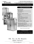
SHELVING INSTALLATION ("DRY" BAKERY)
1
Install shelf supports.
teeth end into stainless
pilasters.
2
Adjust to desired height matching
right and left pairs.
➟
SHELF INSTALLATION:
A. Lift each door up and out of track (do not disconnect elastic tubing). Stretch elastic surgical
tubing and set doors on each side of unit.
B. Locate brackets, lights, shelves, etc. from cabinet
interior.
C. Locate shelf supports wrapped in micro foam
and install teeth end into stainless pilasters
located on interior walls. Adjust to desired
height matching right and left pairs. (images 1 &
2).
D. Locate three horizontal lights wrapped in micro
foam and install (light side down). Electrical
cords should be on the right to plug into side
receptacles.
Hang end hooks of light assembly on two shelf
supports (left and right) slide assembly forward
until it seats in front notch of shelf support.
(image 3).
E. Install rear brackets by sliding end hooks over
rear notch of shelf support. (image 4).
F. Locate shelves, install top shelf first. With the
front lip (tray stop) up and towards cabinet
front, place on top of front light assembly and
snap shelf into (2) clips on top of rear bracket
(image 5).
G. Plug top light assembly into top receptacle of
cabinet interior side wall (image 5).
H. Repeat procedures for remaining two shelves
(image 6).
I. Replace doors in track.
3
Hang end hooks of light
assembly on front notch of
shelf supports.
Receptacle
cap.
4
Install rear brackets.
7
5
Snap shelf into position.
6
WARNING
Shelf mounted lighting requires a
closed circuit. All plugs must be
plugged into side wall receptacles
for lights to work. If less than
three shelves are installed be sure
attached caps are plugged into
receptacle(s) (image 7).
Shelf plug.
Completed assembly.
8
............ www.truemfg.com ............
8
True Food Service Equipment, Inc.
INSTALLATION / OPERATION INSTRUCTIONS
OPTIONAL
(INSTALLING OPTIONAL CASTORS FOR MODELS WITH 12" CORD OPTION ONLY)
CASTOR INSTALLATION:
TOOLS REQUIRED:
• Castor wrench (if not included contact True)
• Adjustable wrench
NOTE
Castors not available for hard wired models.
WARNING
Make sure unit is empty of all its contents (shelving, shelving lighting). Make sure power supply
has been disconnected.
1
A. Curved glass can be damaged if you lay unit
on its back, side, or front. Use a 6" x 6" (15.2
cm x 15.2 cm) block of wood or equivalent.
Slide the block under the cabinet frame rail.
This will support the unit while installing castors.
B. Leg levelers can be backed out by hand
(image 1).
C. Take two threaded castors and thread them
into the existing leg leveler holes. (image 2).
Shims can be used between castor and cabinet frame rail for leveling (image 3). Use the
tool provided to tighten the threaded castors
(image 4).
D. Repeat process for the other side of the cabinet.
Warning
Display case must be
leveled accurately
to ensure front glass
door seals properly.
E. The unit should
be leveled front
to back and side
to side with a
level. Place the
level in the interior floor of the
unit and check
all four sides.
9
Back out leg levelers by hand, or with
adjustable wrench.
2
Thread castors into existing leg leveler
holes.
4
Tighten castor in position with castor
wrench.
3
Use shims as necessary to level cabinet.
............ www.truemfg.com ............
9
True Food Service Equipment, Inc.
INSTALLATION / OPERATION INSTRUCTIONS
OPTIONAL (INSTALLING OPTIONAL FORMICA KIT)
FORMICA KIT INSTALLATION:
FORMICA KIT COMPONENTS:
(2) Formica Top End Panels 103/4"w x 33"h
(27.3 cm x 83.8 cm).
(2) Bottom End Panels
(1) left side, (1) right side (Formica glued to
black plastic panel with 4 key hole slots).
(1) Formica Front Panel
width will vary x 75/8"h (19.4 cm)
NOTE
Please use care when installing the Formica.
Formica can chip, crack, or break.
NOTE
Refer to image 1 for placement of Formica panels.
A. Install the front Formica panel.
Be sure bottom end panels are off in order to
install front panel. Slide front panel into top
and bottom tracks on the front of the cabinet.
Make sure panel is even on both left and right
end of the cabinet (images 1 & 2).
B. Install the top end Formica panels (one on
each side.
Be sure bottom end panels
are off in order to install
top end Formica panel.
Both top end panels are the
STEP A
same size so they each can be
used for left or right of the cabinet.
Slide panel up into black plastic tracks on the
top side panel of each end of cabinet (images
1 & 3).
NOTE
After installing the bottom end pieces the top end
panel will stay in place.
C. Install the bottom end Formica panels (one on
each side.
(Formica is pre-glued to black plastic panel).
Line up the four keyhole slots in each bottom
end piece to the (4) screws on the side of the
cabinet. Slip the (4) large keyholes from the
bottom end piece over the (4) screws. Then
push down to fasten the bottom end piece
onto the cabinet (images 1 & 3).
NOTE
The bottom left and right pieces are not the same.
The taller part of the bottom end piece goes to the
rear of the cabinet as shown in image 3.
1
STEP C
Four keyholes
on backside.
Formica.
2
Formica top
end panel
will slide up
into plastic
tracks.
10
Formica top
end panel
will rest on
screw.
Formica bottom
end panel will lock
through keyholes on
backside of bottom
end piece.
3
Tracks to
hold Formica.
STEP B
STEP A
Side view of Formica sliding
into place for front panel and
top end panel.
............ www.truemfg.com ............
10
True Food Service Equipment, Inc.
MAINTENANCE, CARE & CLEANING
OPTIONAL (SEALING CABINET TO FLOOR)
to the cove base trim. After cove base trim has
dried, fill in cracks and joints with a caulking
material.
C. When applying a mastic, thoroughly clean both
the cabinet and floor of dirt and grease. Draw
an outline of the cabinet on the floor. Raise and
block the front side of the cabinet. Apply a bead
of mastic to the floor 1/2" (1.3 cm) inside the outline drawn. Lower the cabinet. Raise and block
the rear side of the cabinet. Apply the bead of
mastic, lower the cabinet.
It may be necessary to seal the bakery case to the floor
for local sanitary codes or if the customer so desires.
TRUE recommends either of the following methods.
A. Using a vinyl cove base trim as produced by
Armstrong, Johnson, or Kentile (available at floor
covering suppliers) or
Using mastics available at hardware stores.
B. When applying the cove base trim, thoroughly
clean both the cabinet and floor of dirt and
grease. Apply a recommended contact cement
CABINET CLEANING
•
The exterior may be wiped clean with mild soap
and water. Use a good stainless cleaner on countertop.
CAUTION: Do not use any steel wool, abrasive or
chlorine based products to clean stainless steel surfaces.
11
•
The interior of the display case should be cleaned
periodically and we recommend a mild solution
of diluted baking soda and water which will help
reduce any inherent odors. Do not use harsh
cleaners on any surface of the interior.
............ www.truemfg.com ............
11
True Food Service Equipment, Inc.
MAINTENANCE, CARE & CLEANING
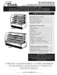
LIGHT BULB REPLACEMENT
D. Install new bulb using spring loaded lampholder.
E. Reinstall light assembly and shelf. Plug cord
into side wall receptacle.
➟
2
Squeeze lampshield and
rotate out.
Remove bulb by gently
pulling up on spring
loaded lampholder.
➟
NOTE
Please be aware of your local ordinances for disposal of old florescent bulbs. These bulbs should
be disposed of in a safe and proper manner.
1
➟
A. Unplug the light assembly from the receptacle
on the interior side wall. Remove shelf and
light assembly from cabinet.
B. Remove the lampshield by gently squeezing
the sides together and rotating out (image 1).
C. Remove bulb from the corded end of assembly
by holding the bulb and gently pulling up on
spring loaded lampholder which will allow
enough clearance to remove bulb (image 2).
NOTE
All spring loaded lampholders are located on the
left side of the cabinet as you face the front.
➟
SHELF MOUNTED BULB REPLACEMENT:
WARNING
When replacing a light bulb make sure power to the
unit is either turned off or unplugged.
3
Squeeze lampshield and
rotate out.
4
Remove bulb by gently pushing
bulb into spring loaded lampholder.
INTERIOR TOP BULB REPLACEMENT:
WARNING
When replacing a light bulb make sure power to the
unit is either turned off or unplugged.
A. Remove the lampshield by gently squeezing
the sides together and rotating out (image 3).
B. Remove bulb by gently pushing bulb back into
spring loaded lampholder which will allow
enough clearance to remove bulb (image 4).
C. Install new bulb using spring loaded lampholder.
D. Reinstall light lampshield by sliding rear "U"
channel of lampshield over metal bracket and
gently squeezing lampshield to fit front "U"
channel over front metal bracket (images 5-6).
E. Image 7 shows assembly properly installed.
12
➟
5
6
Squeeze lampshield "U"
channel into position
over metal bracket.
lampshield "U" channel
in position over metal
bracket.
7
Interior top light assembly
properly installed.
............ www.truemfg.com ............
12
True Food Service Equipment, Inc.
WARRANTY INFORMATION (U.S.A. and Canada ONLY!)
note: warranty information regarding refrigeration components not applicable to non-refrigerated cabinets.
ONE YEAR PARTS & LABOR WARRANTY
TRUE warrants to the original purchaser of every new TRUE refrigerated unit, the cabinet and all parts thereof, to be free from defects in
material or workmanship, under normal and proper use and maintenance service as specified by TRUE and upon proper installation and startup in accordance with the instruction packet supplied with each TRUE unit. TRUE’s obligation under this warranty is limited to a period of one
(1) year from the date of original installation or 15 months after shipment date from TRUE, whichever occurs first.
Any part covered under this warranty that are determined by TRUE to have been defective within one (1) year of original installation
or fifteen (15) months after shipment date from manufacturer, whichever occurs first, is limited to the repair or replacement, including labor
charges, of defective parts or assemblies. The labor warranty shall include standard straight time labor charges only and reasonable travel
time, as determined by TRUE.
ADDITIONAL FOUR YEAR COMPRESSOR WARRANTY
In addition to the one (1) year warranty stated above, TRUE warrants its hermetically and semi-hermetically sealed compressor to be free
from defects in both material and workmanship under normal and proper use and maintenance service for a period of four (4) additional
years from the date of original installation but not to exceed five (5) years and three (3) months after shipment from the manufacturer.
Compressors determined by TRUE to have been defective within this extended time period will, at TRUE’s option, be either repaired or
replaced with a compressor or compressor parts of similar design and capacity.
The four (4) year extended compressor warranty applies only to hermetically and semi-hermetically sealed parts of the compressor and
does not apply to any other parts or components, including, but not limited to, cabinet, paint finish, temperature control, refrigerant, metering
device, driers, motor starting equipment, fan assembly or any other electrical component, etcetera.
404A/134A COMPRESSOR WARRANTY
The four year compressor warranty detailed above will be voided if the following procedure is not carefully adhered to:
1. This system contains R404A or R134A refrigerant and polyol ester lubricant. The polyol ester lubricant has rapid moisture absorbing
qualities. If long exposure to the ambient conditions occur, the lubricant must be removed and replaced with new. For oil amounts and
specifications please call True technical service department (800-325-6152). Failure to comply with recommended lubricant specification will
void the compressor warranty.
2. Drier replacement is very important and must be changed when a system is opened for servicing. A drier using XH-7 desiccant or an
exact replacement solid core drier must be used. The new drier must also be the same capacity as the drier being replaced.
3. Micron level vacuums must be achieved to insure low moisture levels in the system. 500 microns or lower must be obtained.
WARRANTY CLAIMS
All claims for labor or parts must be made directly through TRUE. All claims should include: model number of the unit, the serial number of
the cabinet, proof of purchase, date of installation, and all pertinent information supporting the existence of the alleged defect.
In case of warranty compressor, the compressor model tag must be returned to TRUE along with above listed information.
Any action or breach of these warranty provisions must be commenced within one (1) year after that cause of action has occurred.
WHAT IS NOT COVERED BY THIS WARRANTY
TRUE’s sole obligation under this warranty is limited to either repair or replacement of parts, subject to the additional limitations below. This
warranty neither assumes nor authorizes any person to assume obligations other than those expressly covered by this warranty.
NO CONSEQUENTIAL DAMAGES. TRUE IS NOT RESPONSIBLE FOR ECONOMIC LOSS; PROFIT LOSS; OR SPECIAL, INDIRECT, OR CONSEQUENTIAL
DAMAGES, INCLUDING WITHOUT LIMITATION, LOSSES OR DAMAGES ARISING FROM FOOD OR PRODUCT SPOILAGE CLAIMS WHETHER OR NOT ON
ACCOUNT OF REFRIGERATION FAILURE.
WARRANTY IS NOT TRANSFERABLE. This warranty is not assignable and applies only in favor of the original purchaser/user to whom
delivered. ANY SUCH ASSIGNMENT OR TRANSFER SHALL VOID THE WARRANTIES HEREIN MADE AND SHALL VOID ALL WARRANTIES, EXPRESS OR
IMPLIED, INCLUDING ANY WARRANTY OF MERCHANTABILITY OR FITNESS FOR A PARTICULAR PURPOSE.
IMPROPER USAGE. TRUE ASSUMES NO LIABILITY FOR PARTS OR LABOR COVERAGE FOR COMPONENT FAILURE OR OTHER DAMAGES
RESULTING FROM IMPROPER USAGE OR INSTALLATION OR FAILURE TO CLEAN AND/OR MAINTAIN PRODUCT AS SET FORTH IN THE WARRANTY
PACKET PROVIDED WITH THE UNIT.
ALTERATION, NEGLECT, ABUSE, MISUSE, ACCIDENT, DAMAGE DURING TRANSIT OR INSTALLATION, FIRE, FLOOD, ACTS OF GOD. TRUE is not
responsible for the repair or replacement of any parts that TRUE determines have been subjected after the date of manufacture to alteration,
neglect, abuse, misuse, accident, damage during transit or installation, fire, flood, or act of God.
IMPROPER ELECTRICAL CONNECTIONS. TRUE IS NOT RESPONSIBLE FOR THE REPAIR OR REPLACEMENT OF FAILED OR DAMAGED
COMPONENTS RESULTING FROM ELECTRICAL POWER FAILURE, THE USE OF EXTENSION CORDS, LOW VOLTAGE, OR VOLTAGE DROPS TO THE UNIT.
NO IMPLIED WARRANTY OF MERCHANTABILITY OR FITNESS FOR A PARTICULAR PURPOSE: THERE ARE NO OTHER WARRANTIES, EXPRESSED,
IMPLIED OR STATUTORY, EXCEPT THE ONE (1) YEAR PARTS & LABOR WARRANTY AND THE ADDITIONAL FOUR (4) YEAR COMPRESSOR WARRANTY
AS DESCRIBED ABOVE. THESE WARRANTIES ARE EXCLUSIVE AND IN LIEU OF ALL OTHER WARRANTIES, INCLUDING IMPLIED WARRANTY AND
MERCHANTABILITY OR FITNESS FOR A PARTICULAR PURPOSE. THERE ARE NO WARRANTIES WHICH EXTEND BEYOND THE DESCRIPTION ON THE FACE
HEREOF.
OUTSIDE U.S.: This warranty does not apply to, and TRUE is not responsible for, any warranty claims made on products sold or used outside
the United States.
REMOTE CONDENSERS: True warrants the original purchaser of the remote cabinet one year parts and labor coverage for all cabinet parts
thereof to be free from defects in material or workmanship, under normal and proper use and maintenance service, as specified by True. This
warranty is limited to the cabinet only. True assumes no liability for remote condensing units.
13
............ www.truemfg.com ............
13