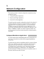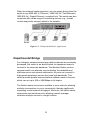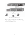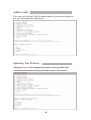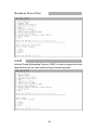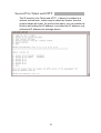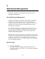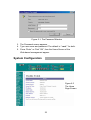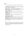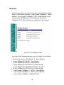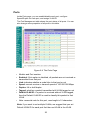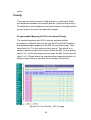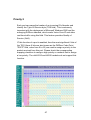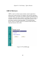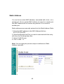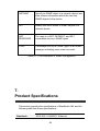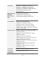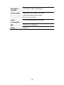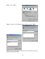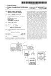
1
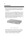
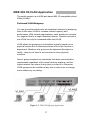
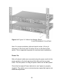
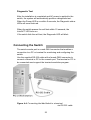
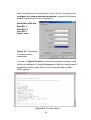
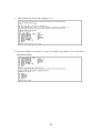
TEG-S4000i
4-Slot SNMP Modular Switch
Ethernet / Fast Ethernet / Gigabit Ethernet
User’s Guide
Version 2.0 23-April-2003
1
Release Note
4 slot modular switch manual
Update
Version
23/04/2003 V2.0
Progress status
On checking
Remark
1. 10/100 TX (48350) spec. MAC: 4K
Buffer:256Kbytes
2. 2/4/8 100FX (48310 ) spec.
MAC12k, Buffer:5Mbytes
3. Gigabit module (48360) MAC:4K,
Buffer 128 Kbytes
2
QA
PM
Richard
Table of Content
Introduction
Product Overview
Network Configuration
Connecting to the Network
Web-Based Management
SNMP Management
Product Specifications
Appendix A.
Internet Explorer Setting
Appendix B.
VLAN Setting
3
1.
Introduction
Welcome to the World of Switching-Network. In modern business
society, communication and information sharing are fundamental to
our lifestyle. Computer networks are one of the fastest means of
communication.
Congratulations on purchasing the Modular Switch. This Modular
Switch is a combination of 4-slot host cabinet and optional 4 kinds of
media modules. A maximum 32 x 10/100Base-TX switched ports
can be achieved using 4 x 8 port 10/100 Base-TX switch modules.
Modular Switch features store-and-forward switching scheme. Every
module has it’s own entry MAC address table to store source
address. The backplane of the Modular Switch can reach up to 10.4
Gbps as to improving network performance.
Figure 1-1 The Modular Switch
Modular Switch with layer 2 management functions, 4 expansion
slots can flexible configure your network. The 4 optional modules
can be 8-Port 10/100 Auto-sensing Intelligent Switch Module,
2/4/8-Port 100 Base-FX Intelligent Fiber Module, Gigabit
1000Base-T Intelligent Switch Modules, and Gigabit
4
1000Base-SX/LX Intelligent Fiber Modules.
With its build-in Web-based Management, managing and configuring
the Modular Switch becomes easier. From cabinet management to
port-level control and monitoring, you can visually configure and
manage your network via Web Browser. Just click your mouse
instead of typing cryptic command strings. However, the Modular
Switch can also be managed via Telnet, Console, or third-party
SNMP Management.
Key Features
Conforms to IEEE 802.3, 802.3u, 802.3z, 802.3ab and
802.3x standards
4 expansion slots to configure flexible network
One built-in intelligent module with RS-232 console
port ( front side )
Supports Half-duplex mode for backpressure, and
full-duplex for flow-control
Store-and-Forward switching architecture for abnormal
packet filtering
Up to 9.6Gbps Back-plane forwarding rate
Mac address: 4K for 8 port 10/100 TX and Gigabit
module, 12K for 2/4/8 port fiber module.
Packet Buffer: 128Kbyts for 8 ports 10/100TX module, 4
Mbytes for 100FX Fiber module, 128KBytes for Gigabit
module
LED System Power, Diagnostic
8 ports TX module: 10/100Mbps,Link/Active,
Full-duplex/Collision;
2/4/8 ports Fiber module: Link/Active,
Full-duplex/Collision
Gigabit Module: Link, Active, Full duplex, Collision
Optional different modules including
Gigabit module ( SX/LX ), Gigabit 1000Base-T, 8-port
auto-sensing 10/100Base-TX switch module, 2/4-port
100BaseFX ( ST/SC/MT-RJ/VF-45 ) fiber module, 8-port
100BaseFX ( MT-RJ/VF-45 ) fiber module
5
Intelligent Module Features
Web-Based Management
SNMP Management
Console and Telnet Management
IEEE 802.1Q Tagging VLAN ( Up to 4095 VLANs )
IEEE 802.1d Spanning Tree Protocol ( STP )
Statistic Address Table for manual address-addition
Port Trunking supported
IGMP supported
Broadcast Storm Filter
Port Mirror
Web Browser Security
Firmware upgradeable trough TFTP
MIB II and Private MIB supported
IEEE 802.1p QoS, ToS
Port Security
Management Methods
The Modular Switch supports following management methods :
Console and Telnet Management
Web-based Management
SNMP Network Management
Console and Telnet Management
Console Management is done through the RS-232 Console Port.
Managing the Modular Switch in this method requires a direct
connection between PC and the Switch. While Telnet management
is done over the network. Once the Switch is on the network, you
can use Telnet to Log in and change the configuration.
6
Web-based Management
The Modular Switch provides an embedded HTML web site residing
in flash memory. It offers advanced management features and allow
users to manage the Modular Switch from anywhere on the network
through a standard browser such as Microsoft Internet Explorer. For
more information, See Section 5 Web-Based Management.
SNMP Network Management
SNMP ( Simple Network Management Protocol ) provides a means
to monitor and control network device, and to manage configurations,
statistic collection, performance, and security.
Data is passed from SNMP agents, which are hardware & software
processes reporting activity in each network device to the
workstation console used to oversee the network. The agent return
information contained in a MIB ( Management Information Base ),
which is a data structure that defines what is obtainable from the
device and what can be controlled.
7
Package Contents
Unpack the carton of the Modular Switch and verify them against the
checklist below.
Modular Switch
Power Cordially
Four Rubber Feet
RS-232 cable
User Guide
Modular Switch
Rack-mounted Kit
Rubber Feet
RS-232 cable
Power Cord
User Guide
Figure 1-2. Package Contents
Compare the contents of your Modular Switch package with the
standard checklist above. If any item is missing or damaged, please
contact your local dealer for service.
8
2.
Product Overview
This section contains the following topics:
Physical Description
Optional Modules
Installing Optional Modules
Software Concepts
Physical Description
The physical dimensions of the HomePNA 312M are:
440mmx 227mm x 67mm ( Lx Wx H )
The Modular Switch is a modular unit, and its chassis contains four
slots. All optional models come with the built-in CPU modules. The
LEDs are located on the front panel of the Switch to allow you to
monitor the operation and performance at a glance. All ports can be
used for network configuration. The RS-232 port is used for
Out-of-Band Management.
Front & Rear Panel
The front panel of Modular Switch displayed in Figure 1-1 is shown
with 8-port 10/100Base-TX Module, 4-port 100Base-FX Fiber
Module and Gigabit 1000Base-T and Gigabit SX Fiber Module.
Figure 2-1. Front Panel
9
The 3-pronged power plug and On/off switched are located at the
Rear Panel of the Modular Switch displayed in Figure 2-2. The
Switch will work with AC in the range 100-240VAC, 50-60Hz.
Figure 2-2.
Rear Pane
LED Indicators
All LED status indicators are located on the FRONT panel of the
switch. They provide a real-time indication of system and operational
status. The ports for connections to other devices and networks are
also on the front panels.
LED
Status
Meaning
Power
Green
Power on
Diag
Red
Alert and problem notice
Green
Device has been connected to the port
Blinks
The data is transmitting on the port
Off
No device attached
Yellow
Port in full duplex mode
Blinks
A collision occurs on the port
Off
No device attached or in half duplex mode
Green
The Port is in 100Mbps mode
Off
Not connected or in 10 Mbps mode
LK/ACT
FD/COL
100
( Only for 8
port 10/100M
Switch Module )
Table 2-1. The above table provides descriptions of the LED status and
their meaning.
10
RS-232 Console
This Console port is used to connect a management station or
terminal with the switch. Out-of-band management means go
through the RS-232 port. For more information about switch
management, see Section 4 “ Connecting to the Network ”.
Software Concepts
Static Address
This feature allows you to enter the addresses that will not be aged
out. It can confine users on certain ports specified by the system
manager, so that they cannot switch to other ports.
Spanning Tree
Spanning Tree Protocol (STP) is an industry standard that prevents
loops configurations in switched networks. The Spanning Tree
algorithm creates a single path through network by making sure that
if more than one path exists between parts of a network, only one of
those paths is used.
This also permits multiple interswitch links to remain active for data
transport while operating in conjunction with the Spanning Tree
algorithm. The IEEE 802.1d Spanning Tree Protocol support for
redundant backbone connections and loop-free networks simplifies
network configuration and improves fault tolerance.
11
Virtual LANs ( VLANs )
A VLAN is a group of switch ports designated by the switch as
belonging to the same broadcast domain.
This feature allows workgroups to be defined on the basis of their
logical function instead of their physical location, and does not
require recabling. It also enables you to configure port-based VLANs
to help isolate broad- cast traffic and increase security, so as to
increase bandwidth to each station.
VLAN also helps you create limited broadcast domains, to prevent
traffic from being forwarded to stations where it is not needed.
Port Trunking
Port Trunking allows you to build higher bandwidth connections by
aggregate several ports into one single group.
Additionally, it may be more cost-effective to trunk multiple lower
speed links than to underutilize a gigabit port. Available copper links
and supported distances are more pervasive for lower speed links.
For example, 100Mbps NICs and switch ports are less expensive
than 1Gbps equipment.
Port trunking also allows end users to protect their investment in
existing infrastructure by reusing current equipment.
SNMP
( Simple Network Management Protocol ) A widely-used network
monitoring and control protocol. Data is passed from SNMP agents,
which are hardware and/or software processes reporting activity in
each network device ( hub, router, bridge, etc. ) to the workstation
console used to oversee the network. The agents return information
contained in a MIB ( Management Information Base ), which is a
data structure that defines what is obtainable from the device and
what can be controlled ( turned off, on, etc.). Originating in the UNIX
community, SNMP has become widely used on all major platforms.
12
Port Mirror
Port mirror allows user to define a destination port and a target port ,
all the packet on the target port will be copy and resend to
destination port, it make user can monitor the packet and won’t
effect the bandwidth of target port.
IGMP
Internet Group Multicast Protocol (IGMP) is used to support
real-time applications such as video conferencing or streaming
audio. IGMP allow you to query for any attached hosts who want to
receive a specific multicast service. The switch looks up the IP
Multicast Group used for this service and adds any port which
received a similar request to that group. It then propagates the
service request on to any neighboring multicast switch to ensure
that it will continue to receive the multicast service.
Port Security
Port Security allow you to restrict specific MAC addresses to reside
in some port. The mean is only packet that with pre-defined MAC
address will be received by the port. It allows user by manual input
the MAC address table.
Priority
There are two priority queues ( high and low ) on each port. Each
port arbitrates between two transmit queues ( high and low priority ).
The arbitration uses weighted round-robin between the high and low
priority queues, and you can adjust this weight.
Broadcast Storm Filter
Storm Filter can avoid any flooded data packets. This feature
prevents the bursts of broadcast traffic. Excessive broadcast
packets ( Broadcast Storms ) can be filtered in our managed switch
by enabling the "Broadcast Storm Filtering" option.
13
3.
Network Configuration
This chapter provides 3 network configuration examples by using
the Modular Switch:
Collapsed Backbone Application
Departmental Bridge Application
Virtual LAN (VLAN) Application
The switch provides versatile configuration options for the network. It
is ideally suited as a workgroup or segment switch in a network; it
aggregate traffic from workgroup switches, or provide dedicated
100Mbps to servers with bandwidth-intensive applications. And
because all Fast Ethernet ports auto-negotiate for operation at 100
Mbps or 1000Mbps ( Gigabit ) the switch is perfectly suited to an
evolving network environment where demand for network speed is
increasing.
Collapsed Backbone Application
For small network where substantial growth can be expected in the
near future, this switch is an ideal solution supporting backbone
connectivity.
The switch can be used as a standalone switch for a group of heavy
traffic users. Switching is brought to the desktop either through a
single end-station per switch port or through a multi-port hub.
A 100 Mbps server is connected to a port, providing end stations
high-speed accessibility to its applications. This configuration
provides dedicated 100 Mbps connections to the network center, to
the server, and the most up to 24 users.
14
When the network needs expansion, you can simply daisy-chain the
switch to any IEEE 802.3 ( Ethernet ), IEEE 802.3u ( Fast Ethernet ),
IEEE 802.3z ( Gigabit Ethernet ) compliant hub. This switch can also
cooperate with a wide range of networking devices (e.g., firewall
routers and printer servers) added to the network.
Figure 3-1. Collapsed Backbone Application
Departmental Bridge
For enterprise networks where large data broadcasts are constantly
processed, this switch is an ideal solution for department users to
connect to the corporate backbone. The Modular Switch used as
segment switch can alleviate user contention for bandwidth and
eliminate server and network bottlenecks. All ports can connect to
high-speed department servers that need high bandwidth. This
switch provides parallel communications between each of its ports,
which can run up to 200 or 2000Mbps at full duplex.
The Switch makes key servers available to more users by allowing
multiple conversations to occur concurrently, thereby significantly
expanding overall network throughput. Moreover, this switch eases
supervision and maintenance by allowing network manager
centralize multiple servers in a single location.
15
Figure 3-2. Departmental Bridge Application
NOTE: Full-duplex operation only applies to point-to-point access
(for example, when attaching the switch to a workstation, server, or
another switch). When connecting to hubs, use a standard cascaded
connection set for half-duplex operation.
16
IEEE 802.1Q VLAN Application
The switch support up to 4095 port-based 802.1Q-compatible virtual
LANs (VLANs).
Port-based VLAN Workgroup
You can group the switch ports into broadcast domains by assigning
them to the same VLAN to increase network capacity and
performance. With network segmentation, each switch port connects
to a segment that is a single broadcast domain. Packets received in
one VLAN can only be forwarded within that VLAN.
VLAN allows the grouping of end stations logically, based not on
physical location but on business policies such as job function or
department. Members of a group can be dispersed throughout a
facility - they do not have to be connected in close physical
locations.
Hence, group members can coordinate their data communication
requirements regardless of the actual working locations; and the
logical network can extend to any point you want it to. Moreover,
VLAN groups can be modified at any time to add, move or change
users without any re-cabling.
Figure 3-3. VLAN Workgroup Application
17
Shared Server
The switch compliant to the IEEE802.1Q tagging VLAN standard
allows ports to exist in multiple VLANs for shared resources, such as
servers, printers, and switch-to-switch connections. It is also
possible to have resources exist in multiple VLANs on one switch as
shown in the following figure.
Figure 3-4. Shared Server
In this example, stations on different VLANs share resources. As a result,
VLAN 1 and VLAN 2 can access VLAN 3 for printing. The broadcasts
from ports configured in VLAN3 can be seen by all VLAN port members
of VLAN3.
18
4.
Connecting to the Network
This chapter provides the installation procedure and instructions for
assigning IP address. This chapter contains following topics:
Pre-instruction requirements
Mounting the switch
Connecting to the switch
Assigning IP address
Pre-Installation Requirements
Before you start hardware installation, make sure your installation
environment has below items:
PCs with 10/100/1000Mbps Ethernet cards: Your PC must
have a standard Ethernet interface to connect to the switch.
UTP cable with RJ-45 connector: Check if the cable and
connectors work properly.
Fiber cable with SC/ST/MT-RJ/VF-45 connector: Check if the
cable and connector types are correct.
A power outlet: 100 to 240V AC at 50 to 60 Hz. Make sure that
the switch power is accessible and cables can be connected
easily.
Dedicated power supply: Use dedicated power circuits or
power conditioners to supply reliable electrical power to the
network devices.
A dry cool place: Keep the switch away from moisture. Avoid
direct sunlight, heat source, and high amount of electromagnetic
interference around.
Mounting tools: If you intend to mount the switch on a rack,
make sure you have all the tools, mounting brackets, screws.
19
Mounting the Switch
The Modular Switch is suitable for use in an office environment
where it can be rack-mounted in standard EIA 19-inch racks or
standalone.
Desktop Installation
Set the Switch on a sufficiently large flat space with a power outlet
nearby. The surface where you put your Switch should be clean,
smooth, level, and sturdy.
Make sure there is enough clearance around the Switch to allow
attachment of cables, power cord and air circulation.
Attaching Rubber Feet
A. Make sure mounting surface on the bottom of the Switch is
grease and dust free.
B. Remove adhesive backing from your Rubber Feet.
C. Apply the Rubber Feet to each corner on the bottom of the Switch.
These footpads can prevent the Switch from shock/vibration.
Figure 4-1. Attaching Rubber Feet to each corner
on the bottom of the Switch
20
Rack Mounting
The Modular Switch come with a rack-mounted kid and can be
mounted in an EIA standard size, 19-inch Rack. The Switch can be
placed in a wiring closet with other equipment.
Perform the following steps to rack mount the switch:
A. Position one bracket to align with the holes on one side of the
switch and secure it with the bracket screws. Then attach the
remaining bracket to the other side of the Switch.
Figure 4-2. Figure 2-4. Attach mounting brackets with screws
B. After attached both mounting brackets, position the Switch in the
rack by lining up the holes in the brackets with the appropriate
holes on the rack. Secure the Switch to the rack with a
screwdriver and the rack-mounting screws.
21
Figure 4-3. Figure 2-5. Mount the Modular Switch
in an EIA standard 19-inch Rack
Note: For proper ventilation, allow at least 4 inches (10 cm) of
clearance on the front and 3.4 inches (8 cm) on the back of the
switch. This is especially important for enclosed rack installations.
Power On
After all network cables are connected, plug the power cord into the
power socket on the back panel and the other end into a power
outlet. Turn the power on using the power switch on the back panel.
Check the front panel Power indicator to see if power is properly
supplied. The switch uses a universal power supply that requires no
additional adjustment.
22
Diagnostic Test
After the installation is completed and AC power is applied to the
switch, the system will automatically perform a diagnostic test.
When the Power LED is on within 5 seconds, the Diagnostic status
LEDs will soon flash red.
When the switch passes the self-test within 10 seconds, the
Link/ACT LED turns on.
If the switch fails the self-test, the Diagnostic LED will blink.
Connecting the Switch
The serial console port is a male DB-9 connector that enables a
connection to a PC or terminal for monitoring and configuring the
switch.
Use the supplied RS-232 cable with a female DB-9 connector to
connect a terminal or PC to the console port. The terminal or PC to
be connected must support the terminal emulation program.
Figure 4-4. Connecting the MaxSwitch to a terminal
via RS-232 cable
23
After connected to the Console port, turn on the PC or terminal and
configure its communications parameters to match the following
default characteristics of the console port:
Baud Rate: 9600 bps
Start Bit: 1
Data Bits: 8
Stop Bit: 1
Parity: none
Figure 4-5. The setting
of communication
parameters
You can run Hyper Terminal or a terminal emulation program using
the above settings for Console Management. After you have finished
parameter settings, press Enter on your keyboard and the Main
Menu appears.
Figure 4-6. The Main Menu
24
Assigning IP Address
After you have attached a terminal or PC with emulation software
and you are ready to make a connection using a web browser. You
have to firstly assign IP information to the switch. It allows you to
manage the switch once it has an IP address.
Once you have logged into the switch, you need to assign an IP
address to the switch’s Ethernet interfaces so that you can connect
to the switch using a web browser.
Select Device settings from the main menu. It prompts you for
System Name, System location, System Contact, IP address,
subnet mask, and default gateway, etc. You should have information
ready before you log into the switch and record them here:
Figure 4-7. The Device Settings page
25
Select IP Address on the Device page, and enter a unique IP
address for the switch, and press Enter. ( Default IP address is
192.168.16.1 )
Select Subnet Mask on the Device page, and enter the subnet mask
( IP Netmask ) address, and press Return. ( Default subnet Mask is
255.255.255.0 )
Select Default Gateway on the Device page, and enter the IP
address of the default gateway if you are sending packets to another
IP network, and press Return. ( Default Gateway is 192.168.16.254 )
Remember returning to the Main Menu to Save the previous settings,
and then Reboot the switch. You may have to press Enter again
when the switch is finished resetting.
Port Setting
This function is for port speed setup. For example, type “1” and “2”
2 of modular 1.
26
to select port
a. More function to choice after typing 1, or 2
b. Pick any number you need to set up, for example, the option 2 is for the Full or
Half mood setting.
27
Address table
User can view the node’s MAC address table of system, per module or
per port, that attached on the device.
Spanning Tree Protocol
Spanning tree is a link management protocol that provides path
redundancy while preventing undesirable loops in the network.
28
Broadcast Storm Filter
IGMP
Internet Group Multicasting Protocol (IGMP) is used to support real-time
applications such as video conferencing or streaming audio.
29
VLAN Mode (2 modes)
VLAN For Cpu(2 VLANs)
30
Secure IP for Telnet and HTTP
The IP security is for Telnet and HTTP , if device is installed in a
internet environment , switch may be attach by Hacker, then the
system maybe will crash, for prevent this status, you can enable the
function and setting the IP address, it provides four IP address, only
authorized IP address can manage device.
31
5.
Web-Based Management
This section introduces the configuration and functions of the
Web-Based management.
About Web-based Management
Inside the CPU board of the Modular Switch exists an embedded
HTML web site residing in flash memory. It offers advanced
management features and allow users to manage the Switch from
anywhere on the network through a standard browser such as
Microsoft Internet Explorer.
The Web-Based Management supports Internet Explorer 5.0 and
later versions. It is based on Java Applets with an aim to reduce
network bandwidth consumption, enhance access speed and
present an easy viewing screen.
Note: By default, IE4.0 does not allow Java Applets to open sockets.
The user has to explicitly modify the browser setting to enable Java
Applets to use network ports. ( See Appendix A: for the means to
modify the setting ) And you don’t need to change any configuration
if you use Netscape browser.
System Login
1. Start Internet Explorer
2. Type http:// and the IP address of the Modular Switch ( for
example, the default is 192.168.16.1 ) in the Location or Address
field. Press Enter.
32
Figure 5-1: The Password Window
3. The Password screen appears.
4. Type user name and password. The default is “ root ” for both.
5. Press “Enter” or Click ”OK”, then the Home Screen of the
Web-based management appear.
System Configuration
Figure 5-2
The Home
Page Screen
33
Home
The Home page displays the configuration of the Modular Switch.
System Name : An administratively-assigned name of the managed
unit, can be modified in SNMP page.
System Location : The physical location of this managed unit ( e.g.,
laboratory, 3rd floor ), can be modified in SNMP page.
System Contact : The contact person for this managed unit, can be
modified in SNMP page.
System Up Time : The time last since the managed unit was reinitialized, read only.
IP Address : The IP address of the managed unit, can be modified
in IP Config page.
Subnet Mask : The subnet mask of the managed unit, can be
modified in IP Config page.
Default Gateway : The default gateway of the managed unit, can be
modified in IP Config page.
MAC Address : The MAC address of the managed unit, read only.
Firmware Version : The firmware version of the management unit,
read only. You can on-line upgrade the new firmware if the new
version is released.
Note: By default, IE4.0 does not allow Java Applets to open sockets.
The user has to explicitly modify the browser setting to enable Java
Applets to use network ports. ( See Appendix A: for the means to
modify the setting ).
34
Modules
Modules page shows the modules that have installed into the Modular
Switch. In the following example, 1-port Gigabit 1000Base-T Switch
Module, 1-port Gigabit 1000Base-F ( SX ) Fiber Module, 8-port
auto-sensing 10/100Base-TX Switch Module, and 4-port
100Base-FX (ST) Fiber Module are installed into the Switch.
Figure 5-3 The Modules Page
Any four of the following modules can be installed to the Switch.
•
•
•
•
•
•
•
•
•
8-port auto-sensing 10/100Base-TX Switch Module
2-port 100Base-FX (SC/ST) Fiber Module
4-port 100Base-FX (SC/ST) Fiber Module
2-port 100Base-FX (MT-RJ/VF-45) Fiber Module
4-port 100Base-FX (MT-RJ/VF-45) Fiber Module
8-port 100Base-FX (MT-RJ/VF-45) Fiber Module
1-port Gigabit 1000Base-F ( SX/LX ) Fiber Module
1-port Gigabit 1000Base-F ( MT-RJ ) Fiber Module
1-port Gigabit 1000Base-T Switch Module
35
Ports
Inside Ports page, you can enable/disable each port, configure
Speed/Duplex for each port, and assign VLAN ID.
The Port Management table shows the port status of all ports. You can
also change some properties of all ports in this table.
Figure 5-4 The Ports Page
•
•
•
•
•
•
•
•
Module and Port number
Enabled: if this option is disabled, all packets are not received or
transmitted from that port
Link: indicates whether a node links to that port or not
Speed: current receive or transmit speed of 10/100/1000 Mbps
Duplex: full or half duplex
Tagged: whether a packet transmitted with VLAN tagged or not
Default VLAN ID: if a packet is received without VLAN tagged,
then the Default VLAN ID is used to classify this packet to that
VLAN
Note: memorial note for this port, max length is 16 characters
Note: if you want to set multiple VLANs, we suggest that you set
Default VLAN ID for each port first then set VLAN in the VLAN
36
window.
Statistics
The Statistic page displays the detailed information about each port.
You can compare and evaluate throughput or other port parameters.
All screen data is updated automatically and you can also update
the data manually.
Figure 5-5-1 The Statistics Page
The Port Counters table shows 8 counters for each port in each module.
•
•
•
•
•
•
•
•
Module and Port number
Bytes RX: the total bytes received from that port
Bytes TX: the total bytes sent from that port
Frames RX: the total packets receives from that port (of all sizes)
Frames TX: the total packets sent from that port (of all sizes)
Broadcast RX: the total broadcast packets received from that port
Multicast RX: the total multicast packets received from that port
CRC Error: the total packets received containing CRC errors from
that port
37
•
Collision: the total number of collisions that occurred during
reception and transmission
You can clear 8 counters of some ports by select the corresponding
"Clear" check boxes then press "Clear" button. To clear all counters
of all ports, press the "Select All" button then "Clear" button.
Statistics 2
The statistics 2 page displays the detailed packet size information
about each port. You can compare and evaluate throughput or other
port parameters. All screen data is updated automatically and you
can also update the data manually.
Figure 5-5-2 The Statistics Page
You can clear packet seize counters of some ports by select the
corresponding "Clear" check boxes then press "Clear" button. To
clear all counters of all ports, press the "Select All" button then
"Clear" button.
38
VLAN ( Virtual LAN )
A port-based VLAN is a group of switch ports designated by the
switch as belonging to the same broadcast domain. If a broadcast
packet is received from a port, it will forward this broadcast packet
only to those ports belonging to the same VLAN. VLAN classification
of every packet is done in the following way: If the packet is tagged
with non-zero VLAN-id field then this is used as the VLAN id.
Otherwise the default VLAN id of the input port is used. You can
assign a single switch port to two or more VLANs. The factory
default VLAN is that all ports belong to the same VLAN group 1.
Creating VLANs increases network flexibility by allowing you to
reassign devices to accommodate network moves, additions, and
changes, eliminating the need to change physical cabling.
The switch support up to 4095 port-based 802.1Q-compatible virtual
LANs (VLANs).
39
Figure 5-6 The VLAN Page
In the VLAN management window, you will see 2 VLANs in the page.
To select a certain VLAN, you can do the following:
•
•
•
•
•
Press ">>" button to display the next 2 VLANs
Press "<<" button to display the previous 2 VLANs
Press ">>|" button to display the last 2 VLANs
Press "|<<" button to display the first 2 VLANs
Enter the VLAN index in the "VLAN" edit box then press "Go to"
button
You can add, edit and remove port members of each VLAN and then
finally press "Apply" button only once to configure the desired
VLANs you want.
Note: if you want to set multiple VLANs, we suggest that you set
Default VLAN ID for each port first in Ports page.
Trunk
Port trunking is the ability to group several 10/100Base-TX or
100Base-FX ports to increase the bandwidth between this switch
and another compatible switch. This is an inexpensive way to
increase bandwidth. We define port trunking as the ability to group
set of ports (up to 8) within the same module into a single logical link.
The port trunk acts as a single link between switches. Multiple trunks
may be implemented in this switch, but only one trunk can be
created within a module.
40
Figure 5-7 The Trunk page
You can add, edit and remove port members of each trunk and then
press "Apply" button after you have finished configuring the trunks
you need.
( Note: Make sure trunking ports are in the same VLAN group. )
STP (Spanning Tree Protocol)
Spanning tree is a link management protocol that provides path
redundancy while preventing undesirable loops in the network. For Layer
2 Ethernet network to function properly, only one active path must exist
between two stations. The spanning-tree algorithm calculates the best
loop-free path throughout a switched network. STP forces redundant
data paths into a standby (blocked) state. If a network segment in the
spanning tree fails and a redundant path exists, the spanning-tree
algorithm recalculates the spanning tree topology and activates the
standby path.
41
Figure 5-8-1 The STP upper page
If you want to participate in spanning tree, have the "Enable
Spanning Tree Protocol" checkbox selected.
The Current Spanning Tree Root describes the unique root switch
information for the instance of spanning tree.
MAC Address: the MAC address of the root switch
Root Max Age: the amount of time (in seconds) protocol information
received on a port is stored by the root switch
Root Hello Time: how often the root switch broadcasts Hello
message to other switches
Root Forward Delay: the amount of time a port will remain in the
listening and learning states before entering the forwarding state
Root Path Cost: the path cost to the root switch from this switch
Root Port: the port providing the best path from the switch to the root
switch
The Spanning Tree Bridge Configuration describes this switch
information in the spanning tree.
Priority: the priority of this switch, default is 32768. The smaller this
value, the higher priority this switch has.
42
Max Age: the amount of time (in seconds) protocol information
received on a port is stored by the root switch, the default value is 20
Hello Time: how often the root switch broadcasts Hello message to
other switches, the default value is 2
Forward Delay: the amount of time a port will remain in the listening
and learning states before entering the forwarding state, the default
value is 15
The Port Configuration describes those ports information in this switch in
the spanning tree.
•
•
•
•
•
Priority: the port priority. The smaller this value, the higher
priority this port has.
Learning: if you want to learn fast, check this checkbox
State: this state of this port. Each port on a switch using STP
exists in one of the following five states:
o Listening
o Learning
o Forwarding
o Blocking
o Disabled
Path Cost: the cost of this port. The smaller this value, the higher
cost this port has. 4 for Gigabit Ethernet and 10 for Fast Ethernet
and FDDI
Root Cost: The cost to the root.
43
Figure 5-8-1 The STP lower page
Note: when you enable the spanning tree protocol, because all ports
in the switch will listen and learn, you may lose communication to
the switch you are managing. Wait about 2 times forward delay
(2*15 seconds), you get the communication again.
44
Port Security
Port Security allow you to restrict specific MAC addresses to reside
in some port. For example, a dummy hub is attached to some port
for extension, and you just only allow 2 users to access this port at
the same time, you can use the port security window to set the
parameters.
Figure 5-9. The Port Security page
To restrict the number of MAC address to reside in a port, you must
do the following :
Click the “ Enable “ checkbox for that port. IF the “ Enable
“checkbox is uncheck, there is no MAC address count restriction
for that port.
Type the number in the “ Max Allowed MAC Address Count
“ edit for that port. The upper bound of this number is the “ Max
Allowed MAC Address Count per port “
Press the “ Press “ button
The “ Used Count “ will tell you how many MAC address residing
in the corresponding port now.
Note : A trunked port is not allowed to enable the port security
45
option.
Priority
There are two priority queues ( high and low ) on each port. Each
port arbitrates between two transmit queues ( high and low priority ).
The arbitration uses weighted round-robin between the high and low
priority queues, and you can adjust this weight.
Programmable Mapping of 802.1p to Internal Priority
The received packets with 802.1q tag are assigned priority
according to a flexible (fixed for the old 48310 and 48320 module)
and programmable mapping of the 802.1p user-priority tag (3 bits,
value from 0 to 7) to the internal priority queue. The default is to
assign a packet to high priority queue when the 802.1p user-priority
tag is 4 to 7, and to low priority queue when the 802.1p user-priority
tag is 0 to 3. Please check the corresponding mapping checkbox to
assign a high priority or uncheck that to assign a low priority.
Figure 5-10. Port Priority – 802.1p page
46
Priority 2
Each port can parse the header of an incoming IPv4 header and
identify the Type-Of-Service byte (TOS field). This is extremely
important with the deployment of Microsoft Windows 2000 and the
emerging DiffServ standard, which marks Voice-Over-IP and other
real-time traffic using this field. This feature provides Quality of
Service (QoS).
IF this function of a port is enabled, then the most significant 6 bits of
the TOS (these 6 bits are also known as the DiffServ Code Point
"DSCP" field, value from 0 to 63) are used to assign a priority to the
packet received from this port. Please check the corresponding
mapping checkbox to assign a high priority or uncheck that to assign
a low priority. The old 48310 and 48320 modules do not support this
function.
47
Figure 5-11. Port Priority – Type of Service
IGMP (IP Multicast)
IGMP is used in multicast communication network applications
where one or more servers, for example, video servers, generate
multicast traffic. If you want your switch to support multimedia and IP
multicast, enable this option (default is enabled). When this option is
enabled, this switch only directs the multicast data packets to the
ports where needed, saving bandwidth. If "Forward with high
priority" option is enabled, then the IP multicast traffic will have a
higher priority than other traffic.
Figure 5-12 The IGMP page
48
Static Address
You can lock a certain MAC address ( associated with a host, ) to a
certain port. Once a certain MAC address is locked to a certain port,
this MAC address will not receive any packets if it is moved to
another port.
Static addresses are manually entered into the Static Address Table.
1. Enter the MAC address in the MAC Address field (ex.
00-11-22-33-44-55).
2. Select the Module and Port you want to associate with this entry
with from the Port drop-down box.
3. Select VLAN Groups.
4. Click <<Add…<<.
Note: You can apply the previous steps to add/remove Static
Address manually.
49
Figure 5-13 The Static Address page
Broadcast Storm Filter
Excessive broadcast packets (broadcast storms) can be filtered in
our managed switch by enabling the "Broadcast Storm Filtering"
option.
When this option is enabled, if more than 3000 packets per second
broadcast packets sent to a port lasts 5 seconds, this port will not
receive any broadcast packets until less than 3000 packets per
second broadcast packets received lasts 5 seconds. If a broadcast
storm happens to a port, you will see a red "BS" text appearing in the
corresponding (module, port) cell, otherwise a "-" text.
Figure 5-14 The Broadcast Storm Filter page
50
Port Mirror
If you want to monitor all receive and transmit packets of one port. You
can do the following:
•
•
•
•
Choose the monitored port in "Mirror Source Port" choice box in
the corresponding mirror source module. Only one port can be
monitored in one module at the same time
Choose the corresponding target module, port in "Mirror Target
Module" and "Mirror Target Port" choice box.
Click the corresponding "Enabled" check box.
Press "Apply" button
Figure 5-15 The Port Mirror page
51
IP Config
You can change the IP address, subnet mask and default gateway
of the managed node. (You can also do that from RS232 console).
Enter the IP address, subnet mask and default gateway in the
corresponding edit box.
If you want to change the user name or password for the managed
node, the following steps is needed:
•
•
•
Click the "Change Password" checkbox
Enter the user name in "Username" edit box
Enter the same password in "Password" and "Confirm
Password" edit box
Press the "Apply" button
You should reboot system to let your settings take effect if you have
changed one of the IP address, subnet mask and default gateway.
52
Figure 5-16 The IP Config page
SNMP
To set system name, system location and system contact, you can
type the desired text string in the corresponding edit box.
To set the "get request" and "set request" community name, you can
type the desired text string in the corresponding edit box. The default
value of get request community is public. The default value of set
request community is private. You must set these two parameters
correctly to perform "get request" from the management unit and
"set request" to the management unit.
53
Figure 5-17 The SNMP page
Save and Reboot
Save
You can save current settings by click the "Current Settings"
checkbox then press the "Apply" button next to the checkbox. You
should reboot the system so that your current settings will take
effect.
54
If you want to use the factory default settings, click the "Factory
Default Settings" checkbox then press the "Apply" button next to the
checkbox. You should reboot the system so that the factory default
settings will take effect.
Reboot
If you want to reboot system, click the "Reboot System" checkbox
then press the "Apply" button next to the checkbox. Please wait a
moment (about 25 seconds) then continue to operate this home
page.
Figure 5-18 Save & Reboot page
Upgrade
You can on-line upgrade the firmware of the managed unit. The
following steps is needed to upgrade the firmware:
•
•
•
Use http or ftp to download the new version firmware from our web
site.
Enter password in the "Password" edit box.
Enter the file downloaded in the "File Path" edit box. (You can use
55
•
"Browse" button to select the file.)
Press the "Upgrade" button.
Figure 5-19 Upgrade page
After you have successfully upgraded the new firmware, please reboot
the system so that the new firmware will take effect.
Note: If you can't upgrade your new firmware successfully, try again
( don't shut down the switch ).
6.
SNMP Management
This section describes how to configure and manage the switch by
accessing Management Information Base (MIB) objects with the
SNMP protocol.
56
SNMP Management
The switch MIB options are accessible through SNMP. Instead of
defining a large set of commands, SNMP performs all operations
using the “GET”, “GETNEXT” and “SET” commands. The SNMP
agent that resides on the switch can respond to MIB-related queries
being sent by the network management software.
The SNMP agent gathers data from the MIB, which keeps
information about device parameters and network data. The agent
can send traps, or notification of certain events, to the manager.
Figure 6-1: SNMP Network
The SNMP manager uses information in the MIB to perform the
operations described below:
Operation
Description
GET
Retrieve values of SNMP objects from a network
device.
57
GETNEXT
Specify an SNMP object in a network device and
then retrieve information about the next few
SNMP objects in the device.
SET
Modify and store values of SNMP objects in a
network device.
GET
RESPONSE
The reply to a GET, GETNEXT, and SET
commands sent by a SNMP agent
TRAP
A message sent by an SNMP agent to an SNMP
manager indicating some event occurred.
Table 6-1. The commands of SNMP management
7.
Product Specifications
This section provides the specifications of MaxSwitch IIM, and the
following table lists these specifications.
Standards
IEEE 802.3 10BASE-T Ethernet,
58
Compliance
IEEE 802.3u 100BASE-TX/FX Ethernet,
IEEE 802.3z 1000BASE-LX/SX Ethernet,
IEEE 802.3ab 1000BASE-T Gigabit Ethernet
ANSI/IEEE standard 802.3 N-Way
Auto-negotiation
Max Forwarding
Rate and
14,880 pps per Ethernet port,
Max Filtering
Rate
1,488,000 pps per Gigabit Ethernet port
LED Indicators
Per Port: 8 port Auto-sensing:
148,800 pps per Fast Ethernet port
100M, LK/ACT, FD/COL ( 3 LEDs )
100M Fiber: LK/ACT, FD/COL ( 2 LEDs )
Gigabit Fiber: LK, ACT, FD, COL ( 4 LEDs )
Gigabit Copper: 1000M, 100M, LK/ACT, FD/COL
Per Unit : Power, Diag
Network Cables
10Base-T: 2-pair UTP/STP Cat. 3, 4, 5 cable
EIA/TIA-568 (100m )
100Base-TX: 2-pair UTP/STP Cat. 5 cable
EIA/TIA-568 (100m)
100Base-FX: 50, 62.5/125 micron
multi-mode fiber-optics ( 2Km ) 8,9/125 micron
single-mode fiber-optics ( 60Km )
1000Base-SX: 50, 62.5/125 micron multi-mode
fiber-optics ( 500m )
1000BASE-LX: 10/125 micron single-mode
fiber-optics ( 10Km )
1000Base-T: 4-pair UTP/STP Cat. 5 cable
EIA/TIA-568 ( 100m )
Dimensions
440mm x 227mm x 66.5mm (L x W x H)
Operational
Temperature
0ºC to 45ºC ( 32ºF to 113ºF )
59
Operational
Humidity
10% to 90% ( Non-condensing )
Power Supply
Input rate: 100~240VAC, 50~60Hz
Internal universal power supply:
DC 3.3V/13A, 5V/4A
Power
Consumption
33~45 Watt depended on modules
EMI
FCC Class A, CE Mark
Safety
cUL, UL
60
Appendix A.
Internet Explorer Setting
If using IE 4.x and later version, you have to modify the browser
setting to enable Java applets to use network ports. We use Internet
Explorer 5.0 as demonstrational sample: We first select ”Internet
Optional..” under “Tools” of function bar, then follow the
step-by-step execution.
Step 1: then select
“ Security ”
Step 2: select ” trusted
sites ”
61
Step 3 : click “ sites ”
Step 4 : add the IP of the Modular Switch to the zone, click " Add "
Step 5: Disable left-bottom box – Require server verification for all sites
in this zone, then click "OK"
62
Step 6: go back to Internet
Options, then click “ Customer
Level ”
Step 7: pull down rolling to find
“Java ”
Step 8: select “ Custom ” under
“Java ”
63
Step 9:select”Java Custom
Setting”
Step 10: select “Edit
Permissions”
Step 11: select “Enable”
under ”Unsigned Content”,
64
Appendix B.
VLAN Setting
In Appendix B, We provide two examples of VLAN management on
VLAN Group Configuration. The two examples will show you how to
Configure VLAN Group:
Port-Based VLAN
The following example shows you how to create 2 Port-based
VLANs including two overlapping ports.
MaxSwitch II M
GROUP 1 VID=1
GROUP 2 VID=2
Ports-->( 1~ 4)
Connect to Port 3
Port-->( 5~8 )
Connect TO Port
5
Work-Station A
Connect to Port 8
Work-Station B
File Server
65
Before you begin to create new VLAN Group, you need to set PVID
number on Ports page as below:
We set VLAN ID of Ports (1~4 ) 1, and PVID of Ports ( 5~8 ) 2.
Remember to click “ Apply “ button after you finish your setting.
Then, return to VLAN page, and the screen displays as below:
66
Afterwards, you click to select Port 4 and Port 5 for the purpose of
overlapping. Remember to click “ Apply “ button after you finish
your setting.
Now you have create two VLAN Groups ( Group1 VID=1 and
Group2 VID=2 ) with overlapping ports ( Port 4 & Port 5 ).
Tagging ( Mac Address based ) VLAN
This method of tagging is defined in the IEEE 802.1Q standard, to
configure switch port by the tagging function that allows the port to
transmit tagging frame. VLAN Tagging can only be used if the
devices at both ends of a link support IEEE 802.1Q.
The following example show you how to create 3 VLAN Groups with
one common tagged port.
MaxSwitch II M
Group 1 VID= 1
Group 2 VID= 2
Group 3 VID= 3
Connect to Port
1
Group 1VID= 1
Connect to Port
802.1Q
VLAN Tag=1
Work-Station A
Work-Station B
67
First, on Ports page, we set VLAN ID 1, 2, 3 as below. Click the
checkbox of Tagged on Module 1, port 1.( ,which is a Gigabit port )
Remember to click “ Apply “ button after you finish your setting.
Then, return to VLAN page, you will see the screen as below.
68
Continue to press 》》button and the next page VLAN 3 appears
Click the checkbox on Port 1, Module 1.
Remember to click “ Apply “ button after you finish your setting.
Now, you have finished one Tagging VLAN setting.
While you connect this Switch to another Modular Switch to form
tagging VLAN, remember that the other Modular Switch should have
the same Tagging VLAN setting.
69
Appendix C.
Technical Support and Service
For this advanced Intelligent Switch, we provide easy access to
technical support information through a variety of services. Here
describes these services.
Registration
Fill in the Registration Card in the package and fax it to the fax
number on the card, or you can visit the online Web site on the card.
Once registered, we will constantly inform you of updated technical
and service information of any new related products.
Problem Report
If any problems occur during your operation, please follow the
Appendix A for troubleshooting. Before contact your dealer, network
supplier or our service support, write down these information on a
paper for a better description: Symptoms, error messages,
frequency, product model name, serial number, part number,
hardware, software and operation system you are using.
Hardware Repair Service
If there are problems with the hardware, you can return the
hardware for repair. Please follow below steps to return you
hardware:
Contact your local dealer or service contact on the Registration card,
describe the problem, and ask for an RMA (Return Merchandise
Authorization) number. If your hardware is still under warranty, you
must also provide your purchase date and where you bought it.
70
If pack your hardware, using the original carton if possible, with RMA
number written on.
After the hardware is repaired, we will inform you, giving you the
delivery date and the amount due. Please send the payment by
T/T(Telegram Transfer). If your hardware is found to be free of
defects, you will only be charged for testing and handling.
Technical Support
TRENDware provides free technical support for customers
worldwide for the duration of the product’s warranty period.
Technical Support via Telephone: +1-310-626-6252
Fax:
+1-310-626-6267
Technical Support via Internet: Http://www.trendnet.com
E-mail: [email protected]
Technical Support Hours:
7:00AM ~ 6:00PM, Monday ~ Friday, Pacific Standard Time (except major holidays)
71