1
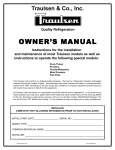
Quality Refrigeration
OWNER’S MANUAL
Instructions for the installation, operation
and maintenance of all Traulsen:
Reach-In Even Thaw Refrigerator Models*
Reach-In Models*
RET132EUT-FHS, RET132EUT-HHS, RET232EUT-FHS, RET232EUT-HHS,
RET232NUT-FHS & RET232NUT-HHS
*For roll-in even-thaw models please refer to form number TR35867.
This Traulsen unit is built to our highest quality standards. We build our refrigerators, freezers and heated
cabinets this way as a matter of pride. This philosophy has made Traulsen the leader in commercial
refrigeration since 1938. We thank you for your choice and confidence in Traulsen equipment and we know
you will receive many years of utility from this equipment.
All Traulsen units are placed on a permanent record file with the service department. In the event of any
future questions you may have, please refer to the model and serial number found on the name tag affixed
to the unit. Should you need service, however, call us on our toll free number, 800-825-8220 between 7:30
am and 4:30 pm CST, Monday thru Friday. It is our pleasure to help and assist you in every possible way.
INSTALLER
COMPLETE THE FOLLOWING INFORMATION PRIOR TO UNIT INSTALLATION
INITIAL START DATE:
SERIAL NO.
MODEL TYPE:
COMPANY/INDIVIDUAL NAME:
INSTALLER:
FORM NUMBER TR35849 REV. 7/05
P/N 375-60214-00
TABLE OF CONTENTS
I.
II.
III.
IV.
V.
THE SERIAL TAG
RECEIPT INSPECTION
INSTALLATION
a-Location
b-Packaging
c-Installing Legs or Casters
d-Tray Slides
e-Cord & Plug
f-Power Supply
g-Wiring Diagram
h-Clearance
OPERATION
a-Even-Thaw Overview
b-Expected Performance
c-Even-Thaw Operation
d-Batch Loading
e-Process Loading
f-Interior Arrangements
g-Adjusting The Temperature Scale
h-Operator Controls, Blower Switch
i-Call Service Light
CARE & MAINTENANCE
a-Cleaning The Condenser
b-Hinge Replacement
c-Replacing The Gaskets
d-Cleaning The Exterior
e-Cleaning The Interior
Page 1
Page 2
Page 2
Page 2
Page 2
Page 2
Page 3
Page 3
Page 3
Page 3
Page 3
Page 3
Page 3
Page 3
Page 3
Page 3
Page 4
Page 4
Page 4
VI.
VII.
VIII.
IX.
X.
XI.
XII.
XIII.
XIV.
XV.
OTHER
a-Service Information
b-Spare Parts
c-Warranty Registration
GEN’L USE, OPERATION & SERVICE SUMMARY
EXPECTED THAW PERFORMANCE/
OPERATIONAL TROUBLESHOOTING
a-Introduction
b-Test Parameters
c-Test Results
d-Results as a Function of Product Mix
e-Incomplete Thawing
f-Equipment Issues
g-Other Causes Of Extended Thaw Times
TROUBLE SHOOTING GUIDE
SPARE PARTS LIST
WIRING DIAGRAM - ALL ONE SECTION MODELS
WIRING DIAGRAM - MODELS RET232NUT ONLY
WIRING DIAGRAM - MODELS RET232EUT ONLY
WARRANTY INFORMATION
INDEX
Page 5
Page 5
Page 5
Page 6
Page 7
Page 7
Page 7
Page 7
Page 7
Page 7
Page 7-8
Page 8
Page 9
Page 10
Page 11
Page 12
Page 13
Page 14
Page 4
Page 4
Page 5
Page 5
Page 5
I. THE SERIAL TAG
FORT WORTH, TX.
SERIAL
VOLTS
MODEL
Hz
PH
TOTAL CURRENT
AMPS
MINIMUM CIRCUIT
AMPS
MAXIMUM OVERCURRENT PROTECTION
LIGHTS
WATTS
HEATERS
AMPS
AMPS
REFRIGERANT
DESIGN PRESSURE
TYPE
HIGH
OZ
LOW
REFRIGERANT
DESIGN PRESSURE
TYPE
HIGH
OZ
LOW
370-60294-00 REV (A)
-1-
The serial tag is a permanently affixed sticker on
which is recorded vital electrical and refrigeration data
about your Traulsen product, as well as the model
and serial number. This tag is located in the upper
right interior compartment on all reach-in/pass-thru
and roll-in/roll-thru refrigerator, freezer and dual-temp
models. For hot food models, this tag is located on
the top of the unit behind the louvers to protect it
from the heat.
READING THE SERIAL TAG
• Serial = The permanent ID# of your Traulsen
• Model = The model # of your Traulsen
• Volts = Voltage
• Hz = Cycle
• PH = Phase
• Total Current = Maximum amp draw
• Minimum Circuit = Minimum circuit ampacity
• Lights = Light wattage
• Heaters = Heater amperage (Hot Food units only)
• Refrigerant = Refrigerant type used
• Design Pressure = High & low side operating
pressures and refrigerant charge
• Agency Labels = Designates agency listings
II. RECEIPT INSPECTION
III. INSTALLATION (cont’d)
All Traulsen products are factory tested for performance and are free from defects when shipped. The
utmost care has been taken in crating this product to
protect against damage in transit. All interior fittings
have been carefully secured and the legs or casters
are boxed and strapped inside to prevent damage.
Door keys will be attached to the handle with a nylon
strip. The handle is protected by an easily removable
nylon netting.
III. c - INSTALLING LEGS OR CASTERS:
lieu of legs are available as an optional accessory for
the same models. These are shipped from the factory
packed inside a cardboard box which is strapped to
one of the shelves. Remove the nylon strap and open
the box, it should contain either four (4) legs or four
(4) casters and sixteen (16) bolts.
You should carefully inspect your Traulsen unit for
damage during delivery. If damage is detected, you
should save all the crating materials and make note
on the carrier’s Bill Of Lading describing this. A freight
claim should be filed immediately. If damage is subsequently noted during or immediately after installation, contact the respective carrier and file a freight
claim. Under no condition may a damaged unit be returned to Traulsen without first obtaining written permission (return authorization).
To install the legs or casters, first raise and block the
reach-in a minimum of 7” from the floor. For installing legs, thread the legs into the threaded holes on
the bottom of the cabinet (see figure 1). Be certain
that all legs are tightly secured (legs and casters
should be tightened to 300 inch/pounds, max). When
the unit is set in its final position, it is important for
proper operation that the unit be level. The legs are
adjustable for this purpose, turn the bottom of the leg
counter-clockwise to raise it, clockwise to lower it.
Level the unit from front to back as well as side to side
in this manner, using a level placed in the bottom of
the cabinet.
WARNING: THE CABINET MUST BE BLOCKED AND
STABLE BEFORE INSTALLING LEGS OR CASTERS.
III. INSTALLATION
III. a - LOCATION:
Select a proper location for your Traulsen unit, away
from extreme heat or cold. Allow enough clearance
between the unit and the side wall in order to make
use of the door stay open feature at 120° (self-closing
feature operates up to 90°). The door(s) must be able
to open a minimum of 90° in order to make use of the
maximum clear door width available.
Fig. 1
III. b - PACKAGING:
All Traulsen units are shipped from the factory bolted
to a sturdy wooden pallet and packaged in a durable
cardboard container. The carton is attached to the
wooden skid with the use of large staples. These
should first be removed to avoid scratching the unit
when lifting off the crate.
Please note that Traulsen units are not designed to be
moved while on legs. If the unit requires moving, a
pallet jack or forklift should be used to prevent damage. For installing casters, the casters are “plate”
type, and require the use of four (4) bolts each to secure them firmly to the cabinet bottom at each corner
(see figure 2). The caster bolts are tightened using a
1/2” socket wrench.
Most exterior stainless steel surfaces have a protective vinyl covering to prevent scratching during manufacturing, shipping and installation. After the unit is
installed in place of service, remove and discard the
covering from all surfaces.
To remove the wooden pallet, first if at all possible, we
suggest that the cabinet remain bolted to the pallet
during all transportation to the point of final installation. The bolts can then be removed with a 3/4” socket
wrench. Avoid laying the unit on its front, side or back
for removal of the pallet.
Fig. 2
NOTE: Traulsen does not recommend laying the unit
down on its front, side or back. However, if you must
please be certain to allow the unit to remain in an upright position afterwards for 24 hours before plugging
it in so that the compressor oils and refrigerant may
settle.
III. d - TRAY SLIDES:
Reach-In models are supplied with fourteen (14) pairs
of #1 type tray slides on 4” centers. These are shipped
installed from the factory, and are easily removable
for cleaning without tools.
6” high stainless steel legs are supplied standard for
all Traulsen reach-in Even-Thaw models. Casters in
-2-
III. INSTALLATION (cont’d)
IV. OPERATION (cont’d)
IV. c - EVEN THAW OPERATION:
The Traulsen Even-Thaw cabinet is a refrigerator, with two
important additional features: 1) the ability to introduce
small amounts of heat into the cabinet, and 2) increased
air flow, indicated by the presence of blowers mounted behind the mullion.
III. e - CORD & PLUG:
Most self-contained models are supplied with a cord &
plug attached. It is shipped coiled at the top of the cabinet, secured by a nylon strip. For your safety and protection, all units supplied with a cord and plug include a
special three-prong grounding plug on the service cord. Select only a dedicated electrical outlet with
grounding plug for power source. NOTE: Do not under
any circumstances, cut or remove the round grounding
prong from the plug, or use an extension cord.
The Even-Thaw refrigerator operates continually, the introduction of frozen product lowers the cabinet temperature
below the heater setpoint temperature (37°F). This prompts
the refrigeration system to turn OFF, and the heaters to turn
ON. Anytime the cabinet air temperature is below the heater
setpoint temperature, additional heat is added. Heater operation is controlled proportionally, i.e. the colder the cabinet temperature, the longer the heaters remain in operation. When the cabinet air temperature reaches above the
heater setpoint temperature, the heaters turn OFF.
III. f - POWER SUPPLY:
The supply voltage should be checked prior to connection to be certain that proper voltage for the cabinet wiring is available (refer to the serial tag to determine correct unit voltage). Make connections in accordance with
local electrical codes. Use qualified electricians.
When the cabinet air temperature reaches the upper refrigerator setpoint temperature (40°F), the refrigeration cycle
is initiated. As long as product does not lower the cabinet
temperature below the lower refrigeration setpoint temperature (37°F), the cabinet will continue to cycle between 38°F
and 40°F. Upon completion of a thaw cycle, the thawed
product should then be removed from the Even-Thaw cabinet and placed in a dedicated storage refrigerator.
Use of a separate, dedicated circuit is required. Size
wiring to handle indicated load and provide necessary
overcurrent protector in circuit (see amperage requirements on the unit’s serial tag).
III. g - WIRING DIAGRAM:
Refer to the wiring diagram for any service work performed on the unit. Should you require one, please contact Traulsen Service at (800) 825-8220, and provide the
model and serial number of the unit involved.
IV. d - BATCH LOADING:
The Even-Thaw model can accommmodate any size partial
load, or up to twenty eight (28) 18” x 26” pans of product.
Use of aluminum pans is highly recommended. Product
should be placed on pans in one layer only to allow for
proper air flow.
III. h - CLEARANCE:
In order to assure optimum performance, the condensing unit of your Traulsen unit MUST have an adequate
supply of air for cooling purposes. Therefore, the operating location must either have a minimum of 12” clearance overhead of the condensing unit or allow for unrestricted air flow at the back of the unit. Clearance of at
least 12” above is required in order to perform certain
maintenance tasks.
When completely loaded with frozen product (at approximately -5°F), the interior cabinet air temperature will begin
to drop and approach the product temperature as a result.
When this occurs the heaters begin operation in order to
return the cabinet temperature back up to the heater
setpoint temperature (37°F). This portion of the thaw cycle
may take place for approximately 8 to 12 hours. With a full
product load the interior cabinet temperature should remain at or below 37°F for approximately 8 to 12 hours of
the expected 18-24 hour total thaw cycle time.
IV. OPERATION
IV. a - EVEN-THAW OVERVIEW:
The “Even-Thaw” refrigerator was specially designed
to thaw frozen food product under safe, temperature
controlled conditions. It is not intended as a storage
refrigerator.
IV. e - PROCESS LOADING:
If the cabinet is unloaded as needed and replaced with
frozen product, the average cabinet temperatures remain
higher. A fully loaded cabinet with the refrigeration system cycling from 38°F to 40°F thaws product faster than
one maintaining operation at below 32°F air temperatures
for several hours.
NOTE: USING THIS REFRIGERATOR FOR STORAGE OF
UNCOVERED PRODUCT IS NOT RECOMMENDED.
IV. b - EXPECTED PERFORMANCE:
The Traulsen Even-Thaw refrigerator is designed to thaw a
full load of frozen food product (see BATCH LOADING for
guidelines) in approximately 18 to 24 hours. However, be
aware that actual thawing times will vary depending upon
a number of variables, such as product type, product packaging, density, spacing, etc. Please note that some other
loading variables, such as product location, are not important to thawing and do not effect thaw cycle duration.
IV. f - INTERIOR ARRANGEMENTS:
Each reach-in Even-Thaw model includes 14 pairs of #1 tray
slides (16 gauge stainless steel angle type) for bottom support of either: (1) 18” x 26” pan per pair of tray slides or (2)
14” x 18” pans per pair of tray slides, per section.
-3-
IV. OPERATION (cont’d)
V. CARE & MAINTENANCE
IV. g - ADJUSTING THE TEMPERATURE SCALE:
The Traulsen Even-Thaw model is preset at the factory
to operate within strict temperature parameters. Should
these settings require adjustment, please contact our
Service Department at (800) 825-8220.
V. a - CLEANING THE CONDENSER:
The most important thing you can do to insure a long,
reliable service life for your Traulsen is to regularly clean
the condenser coil.
The condensing unit requires regularly scheduled cleaning to keep the finned condenser clean of lint and dust
accummulation. Keeping the condenser clean allows
the cabinet to operate more efficiently and use less energy.
IV. h - OPERATOR CONTROLS, BLOWER SWITCH:
As delivered from the factory, all RET models are preset
to operate as described in section IV B. However, if
needed the unit can also be set to operate as a high capacity refrigerator.
To clean the condenser, first disconnect electrical power
to the cabinet and lift up the front louver assembly. To
lift this, remove the two screws located on both sides at
the bottom of the louver assembly (see figure 3). Once
the screws are removed, the panel can be pivoted upwards allowing full access to the front facing condenser
(see figure 4). Vacuum or brush any dirt, lint or dust
from the finned condenser coil, the compressor and
other cooling system parts. If significant dirt is clogging the condenser fins, use compressed air to blow
this clear.
To accomplish this a Blower Switch is located behind the
cabinet louvers towards the center. It is labeled ON/OFF.
As delivered, this is in the ON position, allowingthe unit
to operate in the even-thaw mode. When in the OFF position, this disables two internal mullion blowers, allowing
the unit to operate as a high capacity refrigerator.
Return the Blower Switch to the ON position prior to attempting another even-thaw batch. Failure to do so will
result in increased thaw times.
IV. i - CALL SERVICE LIGHT:
This red light is located above the front panel thermometer. If illuminated, it may indicate a failure or problem with
one of the temperature sensing probes inside the EvenThaw unit. If one of the temperature sensing probes fail,
the unit will default to a preset refrigeration cycle in an attempt to maintain safe product temperatures. The refrigeration system and fans will continue to function.
Lower louver assembly and replace the screws to hold
it in place.
Fig. 3
If the light is illuminated, the unit WILL NOT function in the
thaw mode until the faulty component is repaired. If illuminated, contact your authorized service agent.
Fig. 4
V. b - HINGE REPLACEMENT:
Both the door and hinge can be easily removed from the
cabinet. To remove the door, remove the plug at the
bottom of the top hinge. Inside the hinge there is a small
screw which secures the door in place. Remove this
with a flat head screwdriver and the door can then be
lifted off the hinge. To remove the door portion of the
hinge from the door, lift off the hinge cover and then
remove the three Phillips head screwswhich secure the
hinge in place on the door. To remove the cabinet portion of the hinge, remove the three Phillips head screws
which hold it in place. On solid door units, the top
hinge(s) contains a microswitch for controlling the
interior lighting.
To reassemble the hinge reverse the previous procedure.
-4-
V. CARE & MAINTENANCE (cont’d)
VI. OTHER
V. c - REPLACING THE GASKETS:
To remove the gasket to be replaced, grasp it firmly
by one corner and pull it out. Before attempting to
install a new gasket, both the unit and the gasket itself must be at room temperature. Insert the four corners first by using a rubber mallet (or hammer with a
block of wood). After the corners are properly inserted,
work your way towards the center from both ends by
gently hitting with a mallet until the gasket is completely seated in place (see figure 5 for proper gasket
placement).
VI. a - SERVICE INFORMATION:
Before calling for service, please check the following:
Is the electrical cord plugged in?
Is the fuse OK or circuit breaker on?
Is the power switch “ON”?
If after checking the above items and the unit is still
not operating properly, please contact an authorized
Traulsen service agent. A complete list of authorized
service agents was provided along with your Traulsen
unit. If you cannot locate this, you may also obtain
the name of a service agent from the Tech Service page
of our website: www.traulsen.com.
If service is not satisfactory, please contact our inhouse service department at:
Traulsen
4401 Blue Mound Road
Fort Worth, TX 76106
(800) 825-8220
Fig. 6
Traulsen reserves the right to change specifications
or discontinue models without notice.
NOTE: The gasket may appear too large, but if it is
installed as indicated above it will slip into place.
VI. b - SPARE PARTS:
Spare or replacement parts may be obtained through
a parts supplier or one of our authorized service
agents. A complete list of authorized service agents
accompanies this manual and is also posted on our
company’s official website @ www.traulsen.com.
V. d - CLEANING THE EXTERIOR:
Exterior stainless steel should be cleaned with warm
water, mild soap and a soft cloth. Apply with a dampened cloth and wipe in the direction of the metal grain.
Avoid the use of strong detergents and gritty, abrasive cleaners as they may tend to mar and scratch the
surface. Do NOT use cleansers containing chlorine,
this may promote corrosion of the stainless steel.
VI. c - WARRANTY REGISTRATION:
For your convenience, the warranties on your new
Traulsen unit may be registered with us by one of two
methods. Completing the enclosed warranty card
(shipped with the unit), or by filling out the on-line
warranty registration form located on the Technical
Service page of our website (www.traulsen.com).
Care should also be taken to avoid splashing the unit
with water, containing chlorinated cleansers, when
mopping the floor around the unit.
For stubborn odor spills, use baking soda and water
(mixed to a 1 TBSP baking soda to 1 pint water ratio).
V. e - CLEANING THE INTERIOR:
For cleaning both stainless steel and anodized aluminum interiors, the use of baking soda as described in
section “V. d” is recommended. Use on breaker strips
as well as door gaskets. All interior fittings are removable without tools to facilitate cleaning.
-5-
VII. GENERAL USE, OPERATION & SERVICE SUMMARY
VI. a - INTRODUCTION/OVERVIEW:
The Traulsen Even Thaw is designed to be used as a
thawing cabinet. While it may be utilized in a
refrigeration mode, that is not its intended use. Its
function is to hold the cabinet temperature in the
range from 38 to 40 degrees to thaw product within
the food-safe temperature zone. It has not been
configured to hold colder product temperatures in the
35 to 38 deg F range as desired by some customers.
VI. b - LOADING GUIDELINES:
The Even-Thaw model can accommodate any size
partial load, or up to (28) 18” x 26” pans of product (for
example approximately 672 lbs. of chicken). Use of aluminum pans is highly recommended. Product should be
placed on pans in one layer only to allow for proper airflow. With a full load thaw time will be between 22 & 24
hours. Overloading and/or double wrapping product will
extend thaw times.
Frozen product placed into the unit will pull the
cabinet temperature below the heater set point (37
deg.) and the unit will begin to function in the thaw
mode. This prompts the refrigeration system to turn
OFF, and the heaters to turn ON. The fans remain ON,
circulating this cold air around the product, allowing
for rapid thawing. When cabinet air temperature
reaches the upper set point (38 deg. although the
product is actually much colder), the heaters turn OFF.
VI. c - LED LIGHTS:
The controller has two LED lights that can be useful. One
is marked H, which will be lit when in the Refrigeration
mode. The other is marked G and will be lit during the
Thaw mode. When the H LED is lit the controller will
supply line voltage to the compressor relay coil closing
the N/O contacts in turn supplying line voltage to the
condensing unit. When the G LED is lit the controller
will supply between 3 to 30 VDC to the solid-state relay
coil closing the N/O contacts in turn supplying line
voltage to the mullion heater.
As the cabinet temperature reaches the heater set
point, the heat will be cycled off while the internally
generated heat from the circulation fans continues to
add heat to the cabinet. If sufficient cold capacity or
possibly other frozen product is added to the unit and
subsequently lowers the cabinet temperature more
than 1 degree below the heater set point, the heat will
again turn on to thaw the product.
VI. d - CALL SERVICE LIGHT:
If lit, this indicates that one of the two temperature
sensors is either OPEN or SHORTED. To check the
resistance value per given temperature is correct place
the sensor in an ice bath (32 deg.). The resistance value
should be 100 ohms + 2%. There is a cabinet sensor
inside the heater/blower chamber and another sensor in
the evaporator coil.
If the cold capacity of the product no longer sufficiently
pulls down the cabinet temperature below the heater
set point, the cabinet temperature will slowly rise to
attain the evaporator coil cut-in set point (41 deg.) and
energize the refrigeration system. The unit will remain
in the refrigeration mode until the cabinet
temperature pulls down to the compressor cut-out set
point (38 deg.). The unit will continue to operate and
cycle in the refrigeration mode.
The units incorporate a mode switch located behind
the louvered panel. Switching to the Refrigeration
mode (switch OFF) will turn off two internal blower fans
and will reduce the Thaw mode (switch ON)
performance. Subsequently, switching to the Thaw
mode will have reduced refrigeration performance.
The controller has been preset at the factory and
should not require any adjustments. Traulsen
engineering EXPECTS no changes be made to any set
points or parameter settings without discussing the
situation and obtaining approval to do so. Modifying
the default set points could disrupt the operation/
functional programming algorithm and result in erratic
unit operation.
-6-
VIII. EXPECTED THAW PERFORMANCE/OPERATIONAL TROUBLESHOOTING
VIII. a - INTRODUCTION:
Even thaw performance is a function of many factors,
especially those involving product types and loading.
As a result, actual thaw times will vary as even similar
sized loads of the same product will exhibit some
differences in their thawing characteristics.
VIII. f - EQUIPMENT ISSUES:
If improper loading has been eliminated as a possible
cause for extended thaw cycle times, there are
several system checks which can be done to diagnose
the Traulsen Even-Thaw unit.
First, the amp draw should be checked early in the
thaw cycle. Shortly after loading the unit with frozen
product, the electronic control LED, “G”, should be
illuminated as the cabinet temp will probably be in the
30 to 34 degree F range as per the control read-out.
At this time, full heat should be on. This is a 1300 watt
heater, 115 vac, is about 11.3 amps. Add 4 blowers at
1.1 amps and a few amps for the controls and the total
amp draw should be approximately 16 to 16.5 amps.
VIII. b - TEST PARAMETERS:
To provide a general performance baseline, Traulsen
performed some controlled testing in our lab which
may provide the operator with an approximate idea on
what to expect from their Even-Thaw unit. Full load
batches of frozen product were used as follows:
ONE SECTION MODELS
336 lbs. of chicken, distributed between 14 tray levels.
Each level consisted of 24 lbs. of product loaded into
two pans (four 6 lb. pkgs. of frozen product total per
level/two 6 lb. pkgs. per tray).
When the cabinet temperature reaches 36°F, the LED
“G” will pulse indicating the heat is now being
applied at a 50% level. At 37°F, the LED “G” will be
turned off indicating thaw heat is off. This cycle will
repeat until the cabinet temperature stabilizes between
37-41°F. When the cabinet temperature exceeds 41°F,
the LED “H” illuminates indicating that the cabinet has
switched to refrigeration cycle. The cabinet will now
cycle between 37-41°F in order to maintain cabinet
temperature.
TWO SECTION MODELS
672 lbs. of chicken, distributed between 28 tray levels.
Each level consisted of 24 lbs. of product loaded into
two pans (four 6 lb. pkgs. of frozen product total per
level/two 6 lb. pkgs. per tray).
Also, be certain that the thaw switch has not been
turned OFF. This is located behind the louvers and
has a protective guard around it. This switch can turn
OFF 2 of the 3 mullion blowers and reduce airflow
which reduces thaw capability. In addition, the blower
wattage actually adds heat to the unit and helps
augment the units thawing capability.
VIII. c - TEST RESULTS
Under these actual load parameters, the one-section
model generally required approximately 19-22 hours
in order to completely thaw the entire load. The twosection model required approximately 24-26 hours to
completely thaw the entire load.
VIII. g - OTHER CAUSES OF EXTENDED THAW TIMES:
Some frozen products are often stored in large,
irregularly shaped packages. If used, these should
always be located along the outside wall with the
largest packages being placed closest to, but not
directly against, the wall. It is IMPERATIVE that such
large packages not be placed up against the center
mullion air ducts. This could result in blocked airflow.
REDUCED AIR MOVEMENT EQUATES TO LONGER
THAWING TIMES.
VIII. d - RESULTS AS A FUNCTION OF PRODUCT MIX:
The above thaw times were based upon a mixed load
of different chicken products typically found in many
establishments. It is important to note that initially, all
tests performed were based on a mixed load of
product. This consisted of approximately 1/4 nuggets,
1/4 strips, 1/4 to 1/3 breasts. This MIXED batch thawed
in the times listed above. In actual operation, thaw
batches consisting of a single type of product, or other
ratios of different products may require more time for
thawing. Both this and larger size loads can both
contribute to longer thaw times.
Care should also be taken to avoid pushing other pkgs.
of frozen product up against the mullion sheet metal
ducts. Airflow could be blocked resulting in a similar
extended thaw time situation.
VIII. e - INCOMPLETE THAWING:
In operation, incomplete thawing (i.e. bags of product
in which not every piece was completely thawed) has
been found to usually be the result of those pkgs.
respective pan level having had restricted airflow due
to overloading (from stacked pkgs. or irregular shaped
packages that blocks air from getting to the pkgs.
closest to the cabinet interior side wall or rear).
Allowing for proper air-flow around each pkgs. of
frozen product should eliminate this situation from
occurring.
Another scenario to avoid is for packages to be placed
inadvertently up against the outside walls. They will
also block air flow down the sides of the unit. This is
especially an issue with the right side wall
because when the unit returns to normal refrigerated
operation mode, the cold air flows from the upper right
ceiling evaporator outlet, down the wall, and then
mixes into the cabinet, distributed by all the mullion
blowers. If the right wall is blocked, and especially if
blocked near the top right of the cabinet, the cold
-7-
VIII. OPERATIONAL TROUBLESHOOTING (cont’d)
VIII. g - OTHER CAUSES OF EXTENDED THAW TIMES (cont’d):
evaporator exit air can be short circuited on to the top two or three upper right hand levels and be routed right back
to the return evaporator inlet duct. Therefore, those upper shelves could get very cold and perhaps a substantial
amount of product on the right side could become very cold and possibly even refreeze (as the
evaporator outlet air temperature is 20 degrees F).
IX. TROUBLE SHOOTING GUIDE
FIND YOUR PROBLEM HERE
REMEDY
1. Condensing unit fails to start
a. Check if cord & plug has been disconnected.
2. Condensing unit operates for
prolonged periods or continuously.
a.
b.
c.
d.
3. Food compartment is too warm.
a. Check doors and gaskets for proper seal
4. Condensation on the exterior surface.
a. Check door alignment and gaskets for proper seal.
5. Compressor hums but does not start.
a. Call for service.
6. “Call Service” light is lit.
a. Call for service. A temperature sensing probe may have
failed.
7. Excessively long product thaw times.
a. Review sections “VIII. e” thru “VIII. g”.
b. Call for service.
Are doors closing properly?
Dirty condenser or filter. Clean properly.
Evaporator coil iced. Needs to defrost.
Shortage of refrigerant, call service.
-8-
X. SPARE PARTS LIST
PART NUMBER
APPLIES TO MODEL(S)
PART NAME AND/OR DESCRIPTION
341-60105-00
RET132EUT-FHS
Full Height Door Gasket
SFO-17357-00
RET232EUT-FHS
Full Height Door Gasket
341-60060-00
RET232NUT-HHS
Half Height Door Gasket
341-09501-00
RET232NUT-FHS
Full Height Door Gasket
325-60003-00
RET132EUT & RET232EUT
Filter Drier
325-60003-03
RET232NUT
Filter Drier
325-60080-08
RET132EUT
TXV Valve 134a
325-60080-07
RET232NUT & RET232EUT
TXV Valve 134a
337-60006-00
RET132EUT & RET232NUT
Run Capacitor
337-60006-02
RET232EUT
Run Capacitor
378-29776-00
RET132EUT & RET232NUT
Light Bulb
378-40414-00
RET232EUT
Light Bulb
324-60027-00
All Models
Even-Thaw Controller
337-60324-00
RET132EUT & RET232NUT
Relay 2-Pole, 30 Amp
337-60324-01
RET232EUT
Relay 2-Pole, 30 Amp
337-60308-00
All Models
Sensor Probe
337-60309-00
RET132EUT & RET232NUT
Transformer
337-60309-01
RET232EUT
Transformer
337-60311-00
RET132EUT & RET232NUT
Solid State Relay
337-60311-01
RET232EUT
Solid State Relay
337-29447-00
All Models
Defogger Switch
344-60126-00
All Models
Thermometer
378-60013-00
All Models
Call Service Light
346-28924-42
All Models
Lock Keys T-42
346-13186-42
All Models
Lock Cylinder
346-13189-00
All Models
Lock Bolt
346-60017-00
All Models
Lock Keeper
346-60019-00
All Models
Lock Keeper Bracket
344-13140-01
All Models
6” High Plate Caster
351-25542-00
All Models
Caster Bolt (4 required per caster)
344-37690-00
All Models
Door Handle, Stainless Steel
344-28488-00
All Models
Hinge Cam
344-28486-00
All Models
Hinge Cover
SER-28583-00
All Models
Hinge Assembly
344-13168-01
All Models
6” High Stainless Steel Adjustable Leg
701-60933-00
RET232EUT
#1 Type Tray Slide for 18” x 26” Pans
701-60032-00
RET132EUT & RET232NUT
#1 Type Tray Slide for 18” x 26” Pans
-9-
XI. WIRING DIAGRAM
ALL ONE SECTION MODELS ONLY
-10-
XII. WIRING DIAGRAM
MODELS RET232NUT-FHS & RET232NUT-HHS ONLY
-11-
XIII. WIRING DIAGRAM
MODELS RET232EUT-FHS & RET232EUT-HHS ONLY
-12-
XIV. WARRANTY INFORMATION
STANDARD DOMESTIC WARRANTY
TRAULSEN & CO., INC. warrants new equipment to the original purchaser, when installed within the United States against
defective material and workmanship for one (1) year from the date of original installation. Under this warranty, TRAULSEN
& CO., INC. will repair or replace, at its option, including service and labor, all parts found to be defective and subject to
this warranty. The compressor part is warranted for an additional four (4) years. During this period TRAULSEN & CO.,
INC. will supply replacement compressor(s) if deemed defective, however, all installation, recharging and repair costs
will remain the responsibility of the owner.
This warranty does not apply to damage resulting from fire, water, burglary, accident, abuse, misuse, transit, acts of
God, attempted repairs, improper installation by unauthorized persons, and will not apply to food loss.
THERE ARE NO ORAL, STATUTORY OR IMPLIED WARRANTIES APPLICABLE TO TRAULSEN, INCLUDING BUT NOT LIMITED TO, ANY IMPLIED WARRANTY OF MERCHANTABILITY OR FITNESS FOR ANY PARTICULAR PURPOSE WHICH EXTEND BEYOND THE DESCRIPTION ON THE FACE HEREOF. TRAULSEN SHALL HAVE NO OBLIGATION OR LIABILITY FOR
CONSEQUENTIAL OR SPECIAL DAMAGES, GROWING OUT OF OR WITH RESPECT TO THE EQUIPMENT OR ITS SALE,
OPERATION OR USE, AND TRAULSEN NEITHER ASSUMES NOR AUTHORIZES ANYONE ELSE TO ASSUME FOR IT ANY
OBLIGATION OR LIABILITY IN CONNECTION WITH THE EQUIPMENT OR ITS SALE, OPERATION OR USE OTHER THAN
AS STATED HEREIN.
INTERNATIONAL COMMERCIAL WARRANTY
(for Canadian warranties see domestic US warranty)
TRAULSEN & CO., INC. warrants to the original purchaser the Refrigeration Equipment manufactured and sold by it to be free
from defects in material and workmanship under normal use and service for a period of one (1) year from date of shipment. Under
this warranty, TRAULSEN & CO., INC. will reimburse the purchaser for the replacement of any part of said equipment (excluding
dryers & refrigerant gas) which then proves to be defective. This warranty is void if said equipment or any part thereof has been
subject to misuse, damage in transit, accident, negligence or alteration.
TRAULSEN’S standard warranty does not apply to Export Sales. Rather, for a period of one (1) year from date of original
installation not to exceed Fifteen (15) months from date of shipment from factory, TRAULSEN:
will replace, F.O.B. factory, any defective parts normally subject to warranty.
will not cover the cost of packing, freight or labor such costs being the sole responsibility of the dealer.
THIS WARRANTY IS IN LIEU OF ALL OTHER WARRANTIES EITHER EXPRESSED OR IMPLIED AND CONSTITUTES
TRAULSEN’S FULL OBLIGATION AND LIABILITY. WARRANTIES NOT AVAILABLE ON REMOTE MODELS.
-13-
XV. INDEX
A
B
Batch Loading
Blower Switch
C
Call Service Light
Cleaning
Casters
Cord & Plug
Clearance
Condenser, Cleaning The
M
Mullion Air Ducts
4
4
N
6
5-6
2
3
3
4
D
E
Even-Thaw Operation
Evaporator Outlet
Extended Thaw Times, Causes Of
3
6
6
F
Fan Switch
6
G
Gasket Assembly
Gaskets, Replacing The
4
4
H
Heaters
Hinge, Replacement
3
4
I
Inside Door Pan
Interior Arrangements
6
O
Operational Troubleshooting
7
P
Power Supply
Process Loading
Product Mix - Issues
3
4
6
R
Refrigerations System
Return Authorization
3
2
S
Serial Tag
Spare Parts List
1
9
T
Temperature Scale Adjustment
Troubleshooting
Tray Slides
4
6-7
3, 7
U
4
3
V
Vinyl, Protective Covering
2
W
Warranty Statement
12
Warranty, Registration
Wiring DiagramS
5
10-11
J
X
K
L
LED Lights
Legs
Loading Guidelines
Louver Assembly
Y
Vertical Gasket Retainer
6
2
6
4
Z
-14-
4
HOURS OF OPERATION:
Monday thru Friday 7:30 am - 4:30 pm CST
Traulsen
4401 Blue Mound Road Fort Worth, TX 76106
Phone: (800) 825-8220 Fax-Svce: (817) 740-6757
Website: www.traulsen.com
Quality Refrigeration
© 2005 Traulsen - All Rights Reserved