1
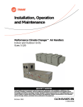
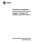
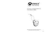
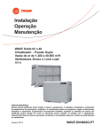
Digital Display Zone Sensor
Literature Order Number: VAV-SVN05B-EN
Ordering number: Single Setpoint: X13790464-01(41901120)
Specifications
Input Power
NEC Class 2, 18-32 Vac 50/60Hz, 24 Vac nominal, 1 VA max
Size
2.8 x 4.5 x 1.2 in. (71.1 x 114.3 x 27.8 mm) including button
heights
Mounting
Vertically flush mount or mount on standard vertical 2 x 4
in. (50.8 x 101.6 mm) device box
Communication Jack
Accessible through bottom of cover
Environmental
Operational: Temperature range 32 to 120°F (0 to 49°C)
Humidity: 5 to 95% non-condensing
Storage: Temperature range –4 to 130°F (-20 to 54°C)
Wiring Diagram
Digital Display Zone Sensor Wiring Terminals
TB1
VAV 4.2
VV550
VV551
MP501
ZN511
ZN517
ZN521
TB1
AC POWER
1
24V AC*
TB1–1
2
24V GND*
TB1–2
TB2
1
ZONE TEMP
2
SENSOR GND
3
SETPOINT
24V
24V
GND
GND
TB3
ZONE SENSOR
TB3–1
2.8"
˚F
˚C
SETPOINT OVERRIDE
4.5"
2.1"
3.3"
24VAC
GND
CANCEL
INPUTS
IN 1
SET
SET
IN 2
TB2
COMM 5
COMM 5
A
A
B
B
TB3–3
Model Diagram
ON
GND
GND
8. Plug holes through the wall behind the sensor to prevent
undesirable airflow.
24VAC
ZN
TB3–2
7. “Sensor Setpoint”output can not be verified with an ohm
meter. Connection to a UCM is necessary to verify
operation.
AH540
AH541
GND
ZONE
6. Sensor must be connected to a UCM and powered up for
at least 1 hour to achieve maximum accuracy.
4
TB3
1
COMM+
TB2–1
2
COMM–
TB2–2
+
–
*Note: Wiring backwards will result in product failure.
Pre-Installation Notes
1. All wiring must be in accordance with NEC and local
building codes.
2. Do not run low-voltage wiring in the same conduit with
high voltage power wiring.
3. Sharing the 24V Class 2-power source from the UCM is
the preferred practice and simplifies installation. See
wiring diagram above and wiring requirements under
Item 4 at right. Use caution to be sure 24V and GND are
connected to the proper terminals when connecting to
the UCM.
4. If a separate 24V Class 2 power source is used to power
the Digital Zone Sensor, terminals TB1-2 (24V GND) and
TB2-2 (Sensor GND) must be jumpered together at the
sensor for the sensor to operate. However, the use of a
transformer with a supply voltage of greater than 150V to
ground as the separate 24V Class 2 power source is not
recommended because its output should be grounded to
building ground (following NEC requirements for Class 2
devices). This additional grounding can affect the
operation and/or damage the Digital Zone Sensor.
5. The sensor display will not be enabled with 24V
connection only. Sensor signal wiring to the UCM must
be connected for the display to function.
WARNING
Installation Instructions
1. Choose mounting location. Choose a spot on an
interior wall near the return air grille about five feet above
the floor. Air should circulate freely and be of average
temperature for the zone. Avoid areas such as:
y behind doors.
y on outside walls or walls facing uncontrolled areas.
y in direct sunlight or near sources of radiant heat that could
affect temperature measurement.
y in-line with discharge air from unit being controlled.
2. Remove cover. Remove zone sensor cover by easing the
tip of a small screwdriver into the top rear center slot
closest to the wall. Gently move the top of the screwdriver
towards you. Excessive force is not recommended for
cover removal!
3. Mount base. Remove zone sensor cover from base and
mount base on wall or 2 x 4 device box.
4. Connect wires. Connect wires as shown in the wiring
diagram. For wire lengths less than 75 feet, an 18 gage, 5
or 6 conductor cable may be used. For wire lengths
greater than 75 feet, use 18 gage, 2-conductor cable for
the power wiring (TB1), and 18 gage, 3 conductor
cable for signal wiring (TB2). Avoid routing wires near
sources of electrical noise such as motors, fluorescent
lights, LAN wiring, etc. In some high noise environments,
signal wires may require shielding. The communication
jack should be wired with the cable appropriate for the
system being installed.
5. Replace Cover. Place zone sensor cover back on the
base and snap securely into place.
Hazardous Voltage!
Disconnect all electric power, including remote disconnects before servicing. Follow proper lockout/tagout procedures
to ensure the power can not be inadvertently energized. Failure to disconnect power before servicing could result in
death or serious injury.
© 2004 American Standard, Inc. All rights reserved
Operating Instructions
Idle Display
y No action
♦ Continuously displays the current zone temperature or
setpoint
Change Setpoint
y Repeatedly press UP or DOWN arrow button
♦ SETPOINT flashes
♦ Display increases or decreases
♦ Release and system returns to the idle display
Begin Timed Override
y Press and hold the ON button until OVERRIDE appears
♦ Timed override begins
♦ System shows the idle display and OVERRIDE
Cancel Timed Override
y Hold CANCEL button until OVERRIDE disappears
♦ Timed override is cancelled
♦ System returns to the idle display
Service Instructions
Balancing Functions:
The * and ** functions allow balancing functionality at the zone sensor. See table below:
Engage
Disengage
Display Override Function Depends on Controller Type
Function
Function
Shows
UCM 4.x
VV550/551
Press “ON” and “UP”
Press “UP” or “DOWN”
Drive air valve to
Drive air valve to
simultaneously until
until normal
*
maximum primary
minimum primary
screen goes blank
display returns
airflow
airflow
Press “ON” and “DOWN”
simultaneously until
screen goes blank
Press “UP” or “DOWN”
until normal
display returns
Change display units (°F or °C)
y Hold UP and DOWN arrow buttons until screen goes blank
y Release buttons
♦ Display shows °F and °C (current unit flashing)
y Press UP or DOWN button to select °F and °C
♦ Selected unit begins flashing
♦ System returns to the idle display
Change idle display from room temperature display
to continuous setpoint display mode
y Hold UP and DOWN arrow buttons until screen goes blank
y Release buttons
♦ Display shows °F and °C (current unit flashing)
y Hold UP and DOWN arrow buttons until screen goes blank
y Release buttons
♦ Displays °F or °C (not flashing)
y Press UP or DOWN arrow buttons
♦ SETPOINT flashes
♦ Display times out and returns in the continuous
setpoint display mode
Adjust the setpoint offset
y Hold UP and DOWN arrow buttons until screen goes blank
y Release buttons
♦ Display shows °F and °C (current unit flashing)
y Hold UP and DOWN arrow buttons until screen goes blank
(con’t., next column)
Literature Order Number
Trane
A business of American Standard Companies
www.trane.com
For more information contact
your local Trane office or
e-mail us at [email protected]
**
Drive unit to unoccupied
(Both flow and
temperature setpoints)
Drive air valve to
maximum primary
airflow
Adjust the setpoint offset (con’t.)
y Release buttons
♦ Displays °F or °C (not flashing)
y Hold UP and DOWN arrow buttons until screen goes blank
y Release buttons
♦ Display shows the setpoint adjust mode
y Hold UP and DOWN arrow buttons
♦ Setpoint offset value changes
♦ System returns to the idle display
Adjust the room temperature display offset
y Hold UP and DOWN arrow buttons until screen goes blank
y Release buttons
♦ Display shows °F and °C (current unit flashing)
y Hold UP and DOWN arrow buttons until screen goes blank
y Release buttons
♦ Displays °F or °C (not flashing)
y Hold UP and DOWN arrow buttons until screen goes blank
y Release buttons
♦ SETPOINT flashes
♦ Display shows the setpoint adjust mode
y Hold UP and DOWN arrow buttons until screen goes blank
y Release buttons
♦ Display shows temperature offset display
y Press UP or DOWN arrow button
♦ Temperature offset value changes
♦ System returns to the current display mode
VAV-SVN05B-EN
File Number
SV-TD-VAV-000-SVN05B-EN-0804
Supersedes
VAV-SVN05A-EN
Stocking Location
Electronic Only
Trane has a policy of continuous product and product data improvement and reserves the right to change design
and specifications without notice. Only qualified technicians should perform the installation and servicing of
equipment referred to in this publication.