1
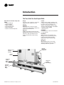
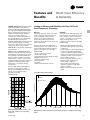
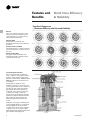
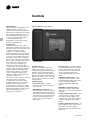
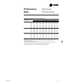
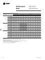
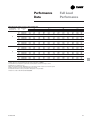
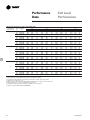
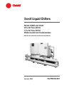
Scroll Liquid Chillers
Model CGWF and CCAF
20 to 60 Tons (60 Hz)
17 to 50 Tons (50 Hz)
Water-Cooled and Condenserless
Built For the Industrial and Commercial Markets
January 2004
CG-PRC012-EN
Introduction
The Trane 20-60 Ton Scroll Liquid Chiller
More Than Just Another “Improved”
Chiller
— Advanced Design
— Better Reliability
— Superior Efficiency
— New CH530 Controls
— Better Availability
— Easier To Install and Operate
Design
The Trane scroll compressor is the most
advanced scroll compressor in the
industry.
Reliability
64 percent fewer compressor parts,
compared to reciprocating compressors,
mean long and reliable life.
Efficiency
CGWF scroll chillers meet and exceed
ASHRAE Standard 90.1 full and part load
efficiencies. Part load efficiencies are
simply unmatched by reciprocating
chillers.
Control
CH530 controls enable scrolling access
to inputs and operating information via
the LCD touch-screen display. Jobspecific communication options allow
greater reporting flexibility. The CH530 is
compatable with LonMark
communications.
Availability
Fast ship cycles on both stock and builtto-order specials.
Installation
Small unit size, factory wiring, easy
lifting provisions, and start-up control
logic mean quick and easy setup.
Chillers fit through standard singlewidth door.
Operation
Smart safety features and over 60
diagnostic displays mean easy and
virtually trouble-free operation.
Microprocessor
Operator
Interface
Rugged
Trane Scroll
Compressor
Control
Panel
Condenser
Leaving
Water
Piping
Evaporator
Leaving
Water Piping
Condenser
Entering
Water
Piping
© 2004 American Standard Inc. All rights reserved.
CG-PRC012-EN
Contents
Introduction
2
Features and Benefits
4
World Class Efficiency and Reliability
Options
Controls
8
Application Considerations
12
Model Number
13
General Data
14
Selection Procedure
15
Performance Data
16
Full Load Performance
Part Load Performance
Adjustment Factors
Pressure Drops
Electrical Data and Connections
27
Typical Wiring Diagram
Field Layout
CG-PRC012-EN
Dimensional Data
32
Weights
37
Mechanical Specifications
38
3
Features and
Benefits
Trane Value Means Fast Availability,
Easy Installation and Quality Service
Packed Stock For Fast Delivery
When your project is a fast-track job,
Trane can help. A wide range of chillers
are stocked and can be shipped soon
after receipt of your order.
Build To Order
Need a special chiller fast? Think Trane
scroll chillers. New manufacturing
technology and inventory control means
the fastest delivery schedule in the
industry. Wide array of standard options
provides the right chiller for the job fast.
Installation
• Only one power connection hook-up —
for fast and inexpensive installation.
• Integrated Comfort™ system means
only single pair connections are
required for control interfaces and
therefore, lower total installation costs.
• Factory refrigerant and oil charged
units help speed installation.
• All units easily fit through a standard
single width door.
• CH530 provides a wealth of
information.
• Factory testing of all Trane equipment
ensures the system works, allowing
smoother start-up & reducing follow-up
costs.
The standard ARI rating condition
(54/44°F and 85°F/3.0 gpm per ton) and
IPLV are ARI certified. All other ratings,
including the following, are outside the
scope of the certification program and
are excluded:
• Glycol.
• 50 Hz.
• Condenserless models CCAF.
4
Easy Serviceability
Trane 20 through 60 ton scroll chillers
are designed with service personnel in
mind. All major components are
replaceable without complete unit
disassembly. Plus, CH530 provides
diagnostic capability to aid service
personnel in analyzing problems.
Therefore, if a problem does occur, the
chiller can be up and running in a shorter
period of time.
Single-Source Responsibility
A wide range of products designed for
complete compatibility are available with
the scroll chillers. Your entire building
comfort system can be completed using
components from Trane.
The Added Value of Applications
Expertise
You get a quality chiller, properly
selected and applied in a properly
designed system. That means a comfort
system that works, the first time!
Water Chiller Systems Business Unit
CG-PRC012-EN
Features and
Benefits
ASHRAE Standard 90.1 All Trane chillers
meet and exceed the new efficiency
levels mandated by ASHRAE Standard
90.1. This new standard requires higher
efficiencies than past technologies can
deliver. It mandates higher efficiency
levels for scroll water chillers in
comparison to reciprocating chillers. In
fact, energy efficiency is so paramount
the US Federal Government has
adopted standard 90.1. Federal Executive
Order mandates energy consuming
devices procured must be in the top 25%
of their class. In the case of chillers,
ASHRAE 90.1 is the product standard for
measurement.
Risk. Not only has ASHRAE 90.1 been
adopted by the US Federal Government,
it’s expected to be adopted domestically,
if not globally, in the future. Make sure
that your chillers as well as your entire
HVAC system complies, or you may be
caught retrofitting your project with new
equipment and paying extra design
dollars if the code changes during
construction.
Trane’s CGWF was designed with the
end user’s requirements in mind.
Efficiency and reliability were primary
design concerns with this latest
generation machine.
World Class Efficiency
& Reliability
Leading in Efficiency and Reliability with State-Of-The-Art
Scroll Compressor Technology
Efficiency
The energy efficiency of the scroll chiller
results in energy costs lower than any
other comparable chiller. Full load
efficiencies are improved beyond
reciprocating chillers, but part load
efficiencies are simply unmatched by any
other manufacturer.
Reliability
The Trane scroll chiller with many new
improvements, now brings an exciting
new compressor to the commercial
market — the Trane scroll compressor.
Trane has designed the scroll
compressor to be a leader in reliability.
HERE’S HOW:
Superior efficiencies are obtained by
combining many of the traditional scroll
chiller energy efficient features with the
Trane scroll compressor technology.
HERE’S HOW:
• Simple design with 64 percent fewer
parts than equal capacity reciprocating
compressor.
• Scroll compliance allows liquid and dirt
to pass through without damaging
compressor (liquid slugging resistant).
• Advanced microelectronics protect both
compressor and motor from typical
electrical fault conditions.
• Scroll compressors have less than a
third the torque variations of a
reciprocating compressor.
• Years of laboratory testing have
optimized compressor and chiller
systems reliability.
• Water-cooled scroll chillers are factory
tested.
• Scroll compressor’s positive
displacement design
• Dual refrigerant circuits (40-60 ton units)
• Multiple compressors
• Optimum system design
• Reduced friction
• No valves
• Advanced heat transfer surfaces
Scroll Chiller Energy Usage Savings
Operating Torque
Typical Reciprocating
Chiller
10-20% Annual Energy Savings
Kilowatt Hours
Scroll Chiller
Chiller Load (%)
Chart illustrates low torque variation of the
Trane scroll compressor vs reciprocating
compressor.
CG-PRC012-EN
Graph illustrates Trane scroll chiller’s superior annual energy costs vs typical reciprocating
chillers.
5
Features and
Benefits
World Class Efficiency
& Reliability
Trane Scroll Compressor
— Maximum Efficiency with Enhanced Reliability
General
The scroll compressor has two scrolls.
The top scroll is fixed and the bottom
scroll orbits. Each scroll has walls in a
spiral shape that intermesh.
Inlet-First Orbit
As the bottom scroll orbits, two
refrigerant gas pockets are formed and
enclosed.
Compression-Second Orbit
The refrigerant gas is compressed as the
volume is reduced closer to the center of
the scroll.
Discharge-Third Orbit
The gas is compressed further and
discharged through a small port in the
center of the fixed scroll.
Scroll Principal Components
This is a cutaway view of a hermetic,
scroll compressor, showing the relative
positions of the principal components.
Shown is a Trane 10-ton, 3600 rpm, 60 Hz
[3000 rpm, 50 Hz] scroll compressor as
an example.
The principle of operation of this
example compressor is as follows: The
suction gas is drawn into the compressor
at A. The gas then passes through the
gap between the rotor and stator, B,
cooling the motor, before it enters the
compressor housing, C. Here, the
velocity of the gas is reduced, causing a
separation of the entrained oil from the
gas stream. The gas then enters the
intake chamber, D, that encircles the
scrolls.
Finally, the suction gas is drawn into the
scroll assembly where it is compressed
and discharged into the dome of the
compressor. The dome of this example
compressor acts as a hot gas muffler
which dampens the pulsations before the
gas enters the discharge line, E.
6
CG-PRC012-EN
Features and
Benefits
Options
Hot Gas Bypass: Hot gas bypass option
allows unit operation below the
minimum step of unit unloading. The
regulator valve, along with all associated
refrigerant piping and electrical wiring,
are factory installed and tested on one
refrigeration circuit. Unit does not start in
hot gas bypass mode. If the unit operates
in bypass mode for 30 minutes without a
call for cooling, it will pump down and
shut off. Unit starts immediately upon a
further call for cooling.
Chilled Water Reset: Front panel settable
control, microprocessor based control
strategy, and field-installed sensor for
ambient temperature based reset are
included in this option. Return water
reset sensor is standard, but panel
controller and control strategy must be
ordered as an option.
Tracer Summit Communication
Interface: Permits bi-directional
communication to the Trane Integrated
Comfort system.
LonTalk LCI-C Communication Interface:
Provides the LonMark chiller profile
inputs/outputs for use with a generic
building automation system.
Remote Input Options
Remote chilled water setpoint input
(4-20mA/2-10Vdc), compressor inhibit
which locks out the second compressor
on each circuit reducing the kW draw or
both.
Options
Ice Making Controls: In ice-making
mode, the unit will operate fully loaded
in response to jobsite supplied contact
closure. Ice making will terminate when
the return fluid temperature falls below
an adjustable setpoint (minimum 20°F
[-6.7°C]). When not in ice making mode,
unit will provide modulating capacity
control based on leaving chilled fluid
temperature (20-55°F) [-6.7°C to 12.8°C].
Unit Mounted Disconnect Switch: Nonfused molded case disconnect switch
factory installed in control panel for
disconnecting main three-phase power.
Isolators: Neoprene-in-shear isolators for
field installation under unit frame.
Sound Attenuation: Factory-installed
acoustical attenuation for applications
where extremely low sound level is
required.
Water Regulating Valves: Field-installed
valves provide means for control of head
pressure.
Outdoor Temperature Sensor: Fieldinstalled outdoor temperature sensor
with an adjustable setpoint provides
means for low ambient lockout.
Condenser Water Temperature Sensor:
Factory installed temperature sensor
provided for microprocessor display.
Control Output Options
Programmable relays provided to
indicate: Compressor running, maximum
capacity, chiller limit mode, warning
(informational diagnostic), alarm latching
(shutdown diagnostic), alarm
nonlatching (shutdown diagnostic),
alarm latching or nonlatching.
CG-PRC012-EN
7
Controls
Human Interfaces
The Trane water-cooled 20-60 ton scroll
CGWF chiller offers an easy-to-use
operator interface panel, the DynaView.
Figure C1. DynaView operator interface
DynaView is an LCD touchscreen display
that is navigated by file tabs. This is an
advanced interface that allows the user
to access any important information
concerning setpoints, active
temperatures, modes, electrical data,
pressures, and diagnostics.
Safety Controls
A centralized main processor offers a
higher level of machine protection. Since
the safety controls are smarter, they limit
compressor operation to avoid
compressor or evaporator failures,
thereby minimizing nuisance shutdown.
Tracer™ Chiller Controls (CH530) directly
senses the control variables that govern
the operation of the chiller: evaporator
pressure and condenser pressure. When
any one of these variables approaches a
limit condition where damage may
occur to the unit or shutdown on a
safety, Tracer Chiller Controls takes
corrective action to avoid shutdown and
keep the chiller operating. This happens
through compressor shedding. Tracer
Chiller Controls optimizes total chiller
power consumption during normal
operating conditions. During abnormal
operating conditions, the
microprocessor will continue to optimize
chiller performance by taking the
corrective action necessary to avoid
shutdown. This keeps cooling capacity
available until the problem can be
solved. Whenever possible, the chiller is
allowed to perform its function; making
chilled water. Overall, the safety controls
help keep the building or process
running and out of trouble.
Standalone Controls
Interface to standalone units is very
simple; only a remote auto/stop for
scheduling is required for unit operation.
Signals from the chilled water pump
contactor auxiliary or a flow switch are
wired to the chilled waterflow interlock.
Signals from a time clock or some other
remote device are wired to the external
auto/stop input.
Standard Features
• External Auto/Stop — A jobsite
provided contact closure will turn the
unit on and off.
• Chilled Water Flow Interlock — A
jobsite provided contact closure from a
chilled water pump contactor and/or a
flow switch is required and will allow
unit operation if a load exists and flow
is proven. This feature will allow the
unit to run in conjunction with the
pump system.
• Emergency Stop — A jobsite supplied
contact opening wired to this input will
turn the unit off and require a manual
reset of the unit microcomputer. This
closure is typically triggered by a
jobsite supplied system such as a fire
alarm.
• Chilled Water Pump Control — Unit
controls provide an output to control
the chilled water pump(s). One contact
closure to the chiller is all that is
required to initiate the chilled water
system.
• Chilled Water Temperature Reset —
Reset can be based on return water
temperature or outdoor air temperature
(optional).
• Condenser Water Pump Control — Unit
controls provide an output to control
the condenser water pump(s). One
contact closure to the chiller is all that is
required to initiate the chilled water
system.
• Condenser Water Flow Protection — A
jobsite supplied contact closure from a
flow switch or pressure switch is
required and will shut down the unit if
flow is lost.
8
CG-PRC012-EN
Controls
Easy Interface to A Generic Building
Management System
Controlling the scroll CGWF chiller with
building management systems is stateof-the-art, yet simple with either the
LonTalk Communications Interface for
Chillers (LCI-C) or Generic Building
Management System Hardwire Points.
Simple Interface with Other Control
Systems
CH530 controls afford simple interface
with other control systems, such as time
clocks, building automation systems,
and ice storage systems. This means
you have the flexibility to meet job
requirements while not having to learn a
complicated control system. This setup
has the same standard features as a
stand-alone water chiller, with the
possibility of having additional optional
features.
What are LonTalk, Echelon, and
LonMark?
LonTalk is a communications protocol
developed by the Echelon Corporation.
The LonMark association develops
control profiles using the LonTalk
communication protocol. LonTalk is a
unit level communications protocol,
unlike BACNet used at the system level.
LonTalk Communications
Interface for Chillers (LCI-C)
LonTalk Communications Interface for
Chillers (LCI-C) provides a generic
automation system with the LonMark
chiller profile inputs/outputs. The inputs/
outputs include both mandatory and
optional network variables. Note:
LonMark network variable names are in
parentheses when different from chiller
naming convention.
Chiller Inputs:
• Chiller Enable/Disable
• Chilled Liquid Setpoint (Cool Setpoint)
• Compressor Inhibit
• Chiller Mode (Ice Making)
Compressor Inhibit
Locks out the second compressor on
each circuit, reducing the kW draw.
Ice Making
Provides interface with ice making
control systems. Please refer to page 11
for more information.
Chiller Outputs:
• On/Off
• Active Setpoint
• Average Percent RLA
• Compressor Inhibit
• Compressor Starts
• Compressor Run Times
• Leaving Chilled Water Temperature
• Entering Chilled Water Temperature
• Evaporator Refrigerant Temperature
• Evaporator Refrigerant Pressure
• Evaporator Water Pump Request &
Flow Status
• Leaving Condenser Water Temperature
• Entering Condenser Water Temperature
• Condenser Refrigerant Temperature
• Condenser Refrigerant Pressure
• Condenser Water Pump Request &
Flow Status
• Outdoor Air Temperature (CCAF)
• Alarm Descriptor
• Chiller Status
Active Setpoint
Indicates the current value of the leaving
water temperature setpoint
Chiller Status
Indicates the running modes and states
of the chiller, i.e. Running in alarm mode,
chiller enabled, chiller being locally
controlled, etc…
Generic Building Management
System Hardwire Points
GBAS may be achieved via hardware
input/output as well. The input/outputs
are as follows:
Chiller Hardwire Inputs Include:
• Chiller Enable/Disable
• Circuit Enable/Disable
• External Chilled Water Setpoint
• Compressor Inhibit
• Ice Making Enable
Programmable Relays and Alarms
The unit provides seven output options,
of which four can be chosen.
a) Compressor running indication
b) Maximum capacity
c) Chiller limit mode
d) Warning informational diagnostic
indication
e) Alarm latching shutdown diagnostic
indication
f) Alarm nonlatching shutdown
diagnostic indication
g) Alarm latching or nonlatching
shutdown diagnostic indication
Average Percent RLA
Provides the current capacity level via %
RLA
Compressor Starts and Run Times
Provides the number of starts and run
time for each compressor
Alarm Descriptor
Provides alarm messages based on predetermined criteria
Chiller Enable/Disable
Allows for chiller to be started or
stopped depending on if certain
operating conditions are met.
Chilled Water Setpoint
Allows for the external setting
independent of the front panel setpoint
to adjust the leaving water temperature
setpoint.
CG-PRC012-EN
9
Controls
Tracer Summit controls — Interface
With The Trane Integrated Comfort
System (ICS)
Trane Chiller Plant Control
The Tracer Summit Chiller Plant Building
Management System with Chiller Plant
Control provides building automation
and energy management functions
through stand-alone control. The Chiller
Plant Control is capable of monitoring
and controlling your entire chiller plant
system.
Application software available:
• Time-of-day scheduling
• Demand limiting
• Chiller sequencing
• Process control language
• Boolean processing
• Zone control
• Reports and logs
• Custom messages
• Run time and maintenance
• Trend log
• PID control loops
And of course, the Trane Chiller Plant
Control can be used on a stand-alone
basis or tied into a complete building
automation system.
10
When the scroll CGWF chiller is used in
conjunction with a Trane Tracer™
Summit system, the unit can be
monitored and controlled from a remote
location. The chiller can be controlled to
fit into the overall building automation
strategy by using time of day
scheduling, timed override, demand
limiting, and chiller sequencing. A
building owner can completely monitor
the chiller from the Tracer system, since
all of the monitoring information
indicated on the unit controller’s
microcomputer can be read off the
Tracer system display. In addition, all the
powerful diagnostic information can be
read back at the Tracer system. Best of
all, this powerful capability comes over a
single twisted pair of wires! The scroll
liquid chillers can interface with many
different external control systems, from
simple stand-alone units to ice making
systems.
A single twisted pair of wires tied directly
between the CGWF chiller and a Tracer™
Summit system provides control,
monitoring and diagnostic capabilities.
Control functions include auto/stop,
adjustment of leaving water temperature
setpoint, compressor operation lockout
for kW demand limiting and control of
ice making mode. The Tracer system
reads monitoring information such as
entering and leaving evaporator water
temperatures and outdoor air
temperature. Over 60 individual
diagnostic codes can be read by the
Tracer system. In addition, the Tracer
system can provide sequencing control
for up to 25 units on the same chilled
water loop. Pump sequencing control
can be provided from the Tracer system.
Tracer ICS is not available in conjunction
the external setpoint capability.
Required Options
Tracer Interface
External Trane Devices Required
Tracer Summit™, Tracer 100 System or
Tracer Chiller Plant Control
Additional Features That May Be Used
Ice Making Control
CG-PRC012-EN
Controls
Trane Chiller Plant Automation
Trane’s depth of experience in chillers
and controls makes us a well-qualified
choice for automation of chiller plants
using scroll liquid chillers. The chiller
plant control capabilities of the Trane
Tracer Summit® building automation
system are unequaled in the industry.
Our chiller plant automation software is
fully pre-engineered and tested. It is a
standard software application, not
custom programming which can prove
to be difficult to support, maintain, and
modify.
Energy Efficiency
Trane chiller plant automation
intelligently sequences starting of
chillers to optimize the overall chiller
plant energy efficiency. Individual chillers
are designated to operate as base, peak,
or swing based on capacity and
efficiency. Sophisticated software
automatically determines which chiller
to run in response to current conditions.
The software also automatically rotates
individual chiller operation to equalize
runtime and wear between chillers.
Trane chiller plant automation enables
unique energy-saving strategies. An
example is controlling pumps, and
chillers from the perspective of overall
system energy consumption. The
software intelligently evaluates and
selects the lowest energy consumption
alternative.
CG-PRC012-EN
Keeping Operators Informed
A crucial part of efficiently running a
chiller plant is assuring that the
operations staff is instantly aware of
what is happening in the plant. Graphics
showing schematics of chillers, piping,
pumps, and towers clearly depict the
chiller plant system, enabling building
operators to easily monitor overall
conditions. Status screens display both
current conditions and upcoming
automated control actions to add or
subtract chiller capacity. CGWF and
other chillers can be monitored and
controlled from a remote location.
Tracer Summit features standard report
templates listing key operating data for
troubleshooting and verifying
performance. Reports for each type of
Trane chiller and three and six-chiller
systems are also standard. Detailed
reports showing chiller runtimes aid in
planning for preventative maintenance.
Swift Emergency Response
We understand the importance of
maintaining chilled water production
while protecting your chillers from costly
damage. If no water flow is detected to a
chiller’s piping, the start sequence is
aborted to protect the chiller. The next
chiller in the sequence is immediately
started to maintain cooling.
In the event of a problem, the operator
receives an alarm notification and
diagnostic message to aid in quick and
accurate troubleshooting. A snapshot
report showing system status just prior
to an emergency shutdown helps
operators determine the cause. If
emergency conditions justify an
immediate manual shutdown, the
operator can override the automatic
control.
Easy Documentation for Regulatory
Compliance
Comprehensive documentation of
refrigerant management practices is
now a fact of life. Trane chiller plant
automation generates the reports
mandated in ASHRAE Guideline 3.
Integrated Comfort™ Capabilities
When integrated with a Tracer Summit
building management system
performing building control, Trane chiller
plant automation coordinates with
Tracer Summit applications to optimize
the total building operation. With this
system option, the full breadth of Trane’s
HVAC and controls experience are
applied to offer solutions to many facility
issues. If your project calls for an
interface to other systems, Tracer
Summit can share data via BACnet™, the
ASHRAE open systems protocol.
Ice Making Systems Controls
An ice making option may be ordered
with the 20-60 ton scroll liquid chiller.
CH530 will accept a command to initiate
ice making. When in the ice making
mode, the chiller will be fully loaded and
will continue to operate until the ice
command is removed or the evaporator
entering water temperature reaches the
active ice termination setpoint. If
terminated on the evaporator entering
water temperature, CH530 will not allow
the chiller to restart until the ice making
command is removed.
Additional Options That May Be Used In
Conjunction
Failure Indication Contacts
Communications Interface (For Tracer
Systems)
Chilled Water Temperature Reset
11
Application
Considerations
Unit Location
Units should be installed indoors where
exposure to rain or water splash is
minimal. A level foundation or flooring
must be provided which will support at
least 150 percent of the operating weight
of the unit. The chiller foundation must be
rigid to reduce vibration transmission to a
minimum. Use of vibration isolators is
recommended for applications with
sensitive vibration and noise criteria.
Allow service clearance for compressor
removal as well as evaporator and
condenser tube removal.
Condenser Water Limitations
Water-cooled scroll chillers start and
operate satisfactorily over a range of load
conditions with uncontrolled entering
water temperature.
Reducing the condenser water
temperature is an effective method of
lowering the power input required.
However, by reducing the condenser
water temperature beyond certain limits,
the effect causes a reduction in the
pressure drop across the thermal
expansion valve to a point when system
instability may occur.
In general, continuous machine operation
with entering condenser water
temperature below 60°F [15.5°C] is not
recommended. When the condenser
water temperature is expected to drop
below 60°F [15.5°C], it is recommended
that some form of condenser water
temperature control be used to ensure
optimal machine performance.
12
Water Treatment
Use of untreated or improperly treated
water in chillers may result in scaling,
erosion, corrosion, algae or slime. It is
recommended that the services of a
qualified water treatment specialist be
engaged to determine what treatment, if
any, is advisable. Trane assumes no
responsibility for the results of untreated,
or improperly treated water.
Water Pumps
Avoid specifying or using 3600 rpm, 60
Hz [3000 rpm, 50 Hz] condenser water
and chilled water pumps. Such pumps
may operate with objectional noise and
vibration. In addition, a low frequency
beat may occur due to the slight
difference in operating rpm between
water pumps and scroll compressor
motors. Where noise and vibration-free
operation is important, Trane
encourages the use of 1750 rpm, 60 Hz
[1450 rpm, 50 Hz] pumps.
Remote Condenser
Remote condensers should be located
as close as possible to the chiller to
ensure minimum pressure drops of
discharge refrigerant. If non-Trane
condensers are provided, a subcooling
circuit must be provided in order to
achieve cataloged performances
(16°F [-8.9°C] subcooling).
CG-PRC012-EN
Model Number
Description
Model Number Description
CGW F 020 4 C A0 U
1,2,3 4 5,6,7 8 9 10,11 12
A
13
Digits 01, 02, 03, – Chiller series
CGWF = Water cooled scroll
chiller
CCAF = Scroll compressor chiller
(condenserless)
Digits 04, – Development sequence
Digits 05, 06, 07 – Unit nominal tonnage
020 = 20 Nominal tons
025 = 25 Nominal tons
030 = 30 Nominal tons
040 = 40 Nominal tons
050 = 50 Nominal tons
060 = 60 Nominal tons
Digit 08 – Unit voltage
G = 208-230/60/3
D = 380/60/3
N = 400/50/3
4 = 460/60/3
5 = 575/60/3
Digit 09 – Ship Cycle
C = Made to order
(C) = Packed stock (Contact BU)
Digit 10, 11 – Design sequence
XX = Factory/ABU assigned
Digit 12 – Agency listing
N = No agency listing
U = C/UL listing
Digit 13 – Pressure vessel code
A = ASME code
C = Canadian code
Digit 14 – Shipping package
A = Ship via flat bed truck
B = Ship w/shrink wrap bag and skid
C = Ship w/skid
Digit 15 – Condenser temperature range
0 = None - CCAF units
1 = Standard 60-90°F [15.6-32.2°C]
entering water temp
4 = High 90-130°F [32.2-54.4°C] entering
water temp
CG-PRC012-EN
A
14
1
15
C L
16 17
1
18
D
19
0
20
N
21
N
22
Digit 16 – Condenser tube material
N = None - CCAF units
C = Std copper finned tubes
Digit 17 – Condenser water connections
N = None - CCAF units
L = Left hand cond water connections
(default)
R = Right hand cond water connections
Digit 18 – Evaporator temperature range
1 = Standard cooling 40-60°F [4.4-15.6°C]
2 = Ice making 26-39°F [-3.3-3.9°C]
3 = Low temp 10-25°F [-12.2-(-3.9)°C]
4 = Standard cooling/Ice making 20-60°F
[-6.7-15.6°C]
Digit 19 – Power line connection type
T = Terminal block
D = Non-fused disconnect switch
Digit 20 – Short circuit rating
0 = No short circuit rating
1 = With short circuit rating
Digit 21 – Control input options
N = No options
R = Remote chilled water setpoint input
C = Remote compressor inhibit and/or
icemaking input
B = Remote CWS and compressor
inhibit/icemaking input
Digit 22 – Control output options
N = No options
P = Programmable relays for remote
alarm, run, etc.
Digit 23 – Auxiliary sensor options
0 = None
1 = Condenser water temp sensors
(CGWF only)
2 = Outdoor temp sensor CWR or Amb Lockout
3 = Both condenser and outdoor
temp sensor
0
23
0
24
N
25
0 X 0
26 27 28
X
29
Digit 24 – Communication options
0 = None
3 = Tracer Summit interface
5 = LonTalk LCI-C interface
Digit 25 – Hot gas bypass
N = NO HGBP valve/function
H = HGBP function included
Digit 26 – Sound attenuator
0 = No sound attenuator
1 = Sound attenuator - factory installed
Digit 27 – Ship-with accessories isolators, WRV
X = No ship-with accessories
N = Neoprene isolators
A = 1.5" 2-way water reg valve x 1
B = 2" 2-way water reg valve x 1
C = 2.5" 2-way water reg valve x 1
D = 1.5" 2-way water reg valve x 2
E = 2" 2-way water reg valve x 2
F = 2.5" 2-way water reg valve x 2
G = Neo isolators + 1.5" WRV x 1
H = Neo isolators + 2" WRV x 1
J = Neo isolators + 2.5" WRV x 1
K = Neo isolators + 1.5" WRV x 2
L = Neo isolators + 2" WRV x 2
M = Neo isolators + 1.5" WRV x 2
Digit 28 – Ship-with accessories - flow
switches
0 = No flow switches
1 = 150 psi NEMA-1 flow switch
(FS4-3) x 1
2 = 150 psi NEMA-1 flow switch
(FS4-3) x 2
4 = 150 psi NEMA-4 flow switch
(FS8-W) x 1
5 = 150 psi NEMA-4 flow switch
(FS8-W) x 2
Digit 29 – Design special
X = Unit has no special features
S = Unit has special design feature
13
General Data
Table GD-1. General data — CGWF water-cooled chiller
Size
Compressor
Quantity (1)
Nominal Size (tons) (2)
Steps of Unloading (%)
Evaporator
Water Storage
(gallons)
(liters)
Min. Flow
(gpm)
(L/s)
Max. Flow
(gpm)
(L/s)
Condenser
Water Storage
(gallons)
(liters)
Min. Flow
(gpm)
(L/s)
Max. Flow
(gpm)
(L/s)
General Unit
Refrigerant
No. of Independent
Refrigerant Circuits
Refrigerant
(pound)
Charge
(kilogram)
Oil Charge
(pints)
(liters)
20
25
30
2
10/10
100,50
2
10/15
100,60
12
45
24
1.5
72
4.5
11
42
30
1.9
90
5.7
16
61
36
2.3
108
6.8
5.0
18.9
30
1.9
90
5.7
6.1
23.2
36
2.3
108
6.8
R-22
1
50
22.7
16
7.6
40
50
60
2/2
10-15/10-15
100,80,60,30
2/2
15-15/15-15
100,75,50,25
13
49
48
3.0
144
9.1
21
80
60
3.8
180
11.4
40
151
84
4.7
252
17.3
7.6
28.9
50
3.2
146
9.2
11.7
44.2
60
3.8
180
11.4
13.9
52.7
72
4.5
216
13.6
14.0
53.1
90
5.7
325
20.5
R-22
R-22
R-22
R-22
R-22
1
50
22.7
22
10.4
1
90
40.8
28
13.2
2
50/50
22.7/22.7
16/16
7.6/7.6
2
50/50
22.7/22.7
22/22
10.4/10.4
2
75/75
34/34
28/28
13.3/13.3
50
60
2/2
10-15/10-15
100,80,60,30
2/2
15-15/15-15
100,75,50,25
2
2/2
15/15 10-10/10-10
100,50 100,75,50,25
Notes
1. Data containing information on two circuits shown as follows: CKT 1/CKT 2
2. Nominal compressor sizes based on 60 Hz.
Table GD-2. General data — CCAF compressor chiller
Size
Compressor
Quantity (1)
Nominal Size (tons) (2)
Steps of Unloading (%)
Evaporator
Water Storage
(gallons)
(liters)
Min. Flow
(gpm)
(L/s)
Max. Flow
(gpm)
(L/s)
General Unit
Refrigerant
No. of Independent
Refrigerant Circuits
Refrigerant
(pound)
Charge
(kilogram)
Oil Charge
(pints)
(liters)
20
25
30
40
2
10/10
100,50
2
10/15
100,60
12
45
24
1.5
72
4.5
11
42
30
1.9
90
5.7
16
61
36
2.3
108
6.8
13
49
48
3.0
144
9.1
21
80
60
3.8
180
11.4
19
72
84
4.7
252
17.3
R-22
R-22
R-22
R-22
R-22
R-22
1
6
2.7
16
7.6
1
8
3.6
22
10.4
1
12
5.4
28
13.2
2
6/6
2.7/2.7
16/16
7.6/7.6
2
8/8
3.6/3.6
22/22
10.4/10.4
2
12/12
5.5/5.5
28/28
13.3/13.3
2
2/2
15/15 10-10/10-10
100,50 100,75,50,25
Notes:
1. Data containing information on two circuits shown as follows: CKT 1/CKT 2
2. Nominal compressor sizes based on 60 Hz.
14
CG-PRC012-EN
Selection
Procedures
The chiller capacity tables on the
following pages cover the most
frequently encountered leaving water
temperatures. For temperature drops
other than 10°F [5.6°C], refer to Table
SP-1, Performance Adjustment Factors,
shown below.
Additional chiller selections and
performance information can be
obtained through your local Trane sales
office.
To select a Trane water-cooled scroll
chiller, the following information is
required:
1. Design load in tons of refrigeration
2. Design chilled water temperature drop
3. Design leaving chilled water
temperature
4. Entering condenser water temperature
Evaporator flow rate (gpm) can be
determined by using the following
formula:
gpm =
Tons x 24
Chilled Water DT (F)
Condenser flow rate (gpm) can be
determined by using the following
formula:
gpm =
24 x (tons + (0.285 x compressor kW)
Condenser Water DT (F)
Table SP-1. Performance adjustment factors
Fouling Water
Evap.
Cond.
Factor Delta T Capacity GPM
kW
GPM
8
0.997
1.231 1.000 0.997
0.00010
10
1.000
1.000 1.000 1.000
12
1.007
0.829 1.001 1.006
14
1.012
0.714 1.001 1.010
16
1.017
0.628 1.002 1.014
Note:
This selection procedure is for water only as the
solution.
Scroll Liquid Chiller — (CGWF) —
Selection Example:
Given:
System Load = 40 tons
Leaving Chilled Water Temperature
(LCWT) = 44°F [6.7°C]
Entering Condenser Water Temperature
(EWT) = 85°F [29.4°C]
Leaving Condenser Water Temperature
(LWT) = 95°F [35°C]
Chilled Water Temperature Drop
= 10°F [5.6°C]
1. From Table PD-1 (Performance Data), a
CGWF 40 at the given conditions will
produce 39.4 tons with a compressor
power input of 30.3 kW and a unit EER
of 15.6.
2. To determine the evaporator and
condenser water pressure drops, the
flow rates (gpm) must be determined.
Using the formula above, this unit
would require an evaporator flow rate
of 95 gpm and a condenser flow rate
of 115 gpm. (Compressor kW is found
in the same table as the capacity.) The
Evaporator Pressure Drop Curve,
Chart PD-1, indicates that 95 gpm
through a 40 ton evaporator results in
a pressure drop of 13.8 feet of water.
The Condenser Pressure Drop curve,
Chart PD-2, indicates 115 gpm through
a 40 ton condenser results in a
pressure drop of 14 feet of water.
3. The final unit selection is:
— Quantity (1) CGWF 40
— Cooling Capacity = 39.4 tons
— Entering/Leaving Chilled Water
Temperatures = 54/44°F [12.2/6.7°C]
Compressor Chiller – (CCAF) – Selection
Example:
Select the unit for the following
conditions:
A compressor chiller is required to
produce 45 tons when matched with an
air-cooled condenser. The leaving chilled
water temperature is 44°F [6.7°C]. The
evaporator temperature differential is
10°F [5.6°C]. The ambient temperature is
95°F [35°C].
1. Select the nominal unit size. The
performance data is tabulated by
leaving chilled water temperature. For
example, the standard unit capacities
at 44°F [6.7°C] leaving chilled water
temperature are found on page 21.
The system that best meets the
tonnage requirement is a CCAF 50
matched with a CAUC C50. The unit
capacity is 47.1 tons with a kW input of
56.3. The compressor chiller EER is
10.0.
2. Calculate the required chilled water
flow rate.
3. gpm =
Tons x 24
Chilled Water DT (F)
From this example,
gpm = 47.1 x 24 = 113
10
4. Determine the evaporator water
pressure drop. The evaporator water
pressure drop is located on page 22.
Entering the evaporator chart at 113
gpm, the pressure drop for a CCAF 50
evaporator is 7.9 feet.
5. Unit Selection
— Evaporator water pressure drop =
13.8 feet
The above procedure shows the
proper selection for this example is a
CCAF 50 with a CAUB C50 condenser
operating as follows:
— Cooling water flow = 115 gpm
— Capacity = 47.1
— Condenser water pressure drop =
14 feet
— Entering/leaving chilled water
temperature = 54/44°F [12.2/6.7°C]
— Compressor power input = 30.3 kW
— Chilled water flow rate = 113 gpm
— Unit EER = 15.6
— Evaporator water pressure drop =
7.9 feet
— Chilled water flow rate = 95 gpm
— Compressor power input = 56.3
— Unit EER = 10.0
CG-PRC012-EN
15
Performance
Data
Full Load
Performance
Table PD-1. 60 Hz CGWF performance data in English units
Evaporator
Leaving Water
Temperature (F)
40
42
44
46
48
50
Unit
Size
20
25
30
40
50
60
20
25
30
40
50
60
20
25
30
40
50
60
20
25
30
40
50
60
20
25
30
40
50
60
20
25
30
40
50
60
Tons
19.2
23.8
28.3
38.0
47.0
57.7
20.0
24.7
29.4
39.5
48.9
59.9
20.8
25.7
30.6
41.1
50.8
62.1
21.5
26.6
31.7
42.6
52.8
64.4
22.4
27.6
32.9
44.2
54.7
66.7
23.2
28.7
34.1
45.9
56.8
69.1
75
kW
13.8
17.2
20.7
27.3
34.1
42.1
13.9
17.3
20.8
27.4
34.2
42.3
13.9
17.4
20.8
27.5
34.4
42.5
14.0
17.4
20.9
27.6
34.5
42.6
14.0
17.5
21.0
27.8
34.6
42.8
14.1
17.6
21.1
27.9
34.8
43.0
EER
16.7
16.5
16.4
16.8
16.6
16.4
17.3
17.1
17.0
17.3
17.2
17.0
17.3
17.7
17.6
17.9
17.7
17.6
18.5
18.3
18.2
18.5
18.4
18.1
19.1
19.0
18.8
19.1
19.0
18.7
19.7
19.6
19.5
19.8
19.6
19.3
Tons
19.0
23.2
27.6
37.2
46.0
56.4
19.8
24.2
28.7
38.7
47.8
58.5
20.5
25.1
29.9
40.2
49.7
60.7
21.3
26.1
31.0
41.7
51.6
63.0
22.1
27.0
32.2
43.3
53.6
65.2
22.9
28.0
33.4
44.9
55.5
67.6
80
kW
14.5
18.1
21.7
28.7
35.8
44.2
14.6
18.2
21.8
28.8
36.0
44.4
14.7
18.3
21.9
28.9
35.1
44.6
14.7
18.3
22.0
29.0
36.3
44.8
14.8
18.4
22.1
29.2
35.4
45.0
14.8
18.5
22.1
29.3
36.5
45.1
Entering Condenser Water Temperature (F)
85
EER
Tons
kW
EER
Tons
15.7
18.6
15.4
14.6
18.1
15.4
22.7
19.1
14.3
22.1
15.3
27.0
22.9
14.1
26.3
15.6
36.5
30.2
14.5
35.5
15.4
44.9
37.7
14.3
43.8
15.3
55.0
46.5
14.2
53.7
16.3
19.3
15.4
15.1
18.9
15.9
23.6
19.2
14.8
23.0
15.8
28.0
23.0
14.7
27.3
16.1
37.8
30.3
15.0
36.9
16.0
46.7
37.9
14.8
45.6
15.8
57.2
46.7
14.7
55.7
16.8
19.9
15.4
15.5
19.6
16.5
24.5
19.1
15.4
23.9
16.4
29.2
22.9
15.3
28.4
16.7
39.4
30.3
15.6
38.4
16.5
48.6
37.8
15.4
47.4
16.3
59.4
46.8
15.2
57.9
17.4
20.9
15.5
16.2
20.4
17.1
25.5
19.3
15.8
24.9
16.9
30.3
23.1
15.7
29.5
17.3
40.8
30.6
16.0
39.9
17.1
50.4
38.2
15.9
49.2
16.9
61.5
47.1
15.7
60.0
18.0
21.6
15.6
16.7
21.1
17.6
26.4
19.4
16.4
25.8
17.5
31.4
23.2
16.2
30.7
17.8
42.4
30.7
16.6
41.4
17.7
52.3
38.3
16.4
51.1
17.4
63.7
47.3
16.2
62.2
18.6
22.4
15.6
17.2
21.9
18.2
27.4
19.4
16.9
26.8
18.1
32.6
23.3
16.8
31.8
18.4
43.9
30.8
17.1
42.9
18.2
54.3
38.5
16.9
53.0
18.0
66.0
47.5
16.7
64.5
90
kW
16.1
20.1
24.1
31.8
39.7
49.0
16.2
20.2
24.2
32.0
39.9
49.2
16.3
20.3
24.3
32.1
40.1
49.4
16.3
20.3
24.4
32.3
40.2
49.6
16.4
20.4
24.5
32.4
40.4
49.8
16.5
20.5
24.6
32.5
40.5
50.0
EER
13.5
13.2
13.1
13.4
13.2
13.1
14.0
13.7
13.6
13.9
13.7
13.6
14.5
14.2
14.0
14.4
14.2
14.1
15.0
14.7
14.5
14.8
14.7
14.5
15.5
15.2
15.0
15.3
15.2
15.0
16.0
15.7
15.6
15.8
15.7
15.5
Tons
17.7
21.6
25.6
34.6
42.7
52.3
18.4
22.4
26.6
36.0
44.4
54.3
19.1
23.3
27.7
37.4
46.2
56.4
19.9
24.2
28.7
38.9
48.0
58.5
20.6
25.2
29.9
40.4
49.8
60.7
21.4
26.1
31.0
41.9
51.7
62.9
95
kW
17.1
21.2
25.4
33.6
41.0
51.7
17.1
21.3
25.5
33.8
42.1
51.9
17.2
21.4
25.6
33.9
42.3
52.1
17.3
21.5
25.7
34.1
42.4
52.3
17.3
21.6
25.8
34.2
42.6
52.5
17.4
21.6
25.0
34.3
42.8
52.8
EER
12.4
12.2
12.1
12.4
12.2
12.1
12.9
12.6
12.5
12.8
12.7
12.6
12.9
13.1
13.0
13.3
13.1
13.0
13.8
13.5
13.4
13.7
13.6
13.4
14.3
14.0
13.9
14.2
14.0
13.9
14.8
14.5
14.4
14.6
14.5
14.3
Notes:
1. Rated in accordance with ARI Standard 550/590-98 with fouling factors of 0.0001 in the evaporator and 0.00025 in the condenser.
2. Consult Trane representative for performance at temperatures outside of the ranges shown.
3. kW input is for compressors only.
4. EER = Energy Efficiency Ratio (Btu/watt-hout). Power inputs include compressors and control power.
5. Ratings are based on an evaporator temperature drop of 10°F.
6. Interpolation between points is permissible. Extrapolation is not permitted.
16
CG-PRC012-EN
Performance
Data
Full Load
Performance
Table PD-2. 60 Hz CGWF performance data in Metric units
Evaporator
Leaving Water
Temperature (C)
6
8
10
Unit
Size
20
25
30
40
50
60
20
25
30
40
50
60
20
25
30
40
50
60
kWo
70.4
87.1
104.0
139.5
172.4
211.0
75.7
93.5
111.4
150.3
185.3
226.0
80.8
99.9
119.0
159.9
197.9
240.7
25
kWi
14.2
17.7
21.2
28.0
35.0
43.2
14.3
17.8
21.4
28.2
35.2
43.5
14.4
17.9
21.5
28.4
35.5
43.8
Entering Condenser Water Temperature (C)
30
COP
kWo
kWi
COP
kWo
5.0
67.7
15.5
4.4
64.7
4.9
83.5
19.4
4.3
79.8
4.9
99.6
23.2
4.3
95.1
5.0
133.9
30.7
4.4
128.1
4.9
165.3
38.3
4.3
157.9
4.9
202.2
47.3
4.3
193.1
5.3
72.7
15.7
4.6
69.6
5.3
89.8
19.5
4.6
85.8
5.2
106.8
23.4
4.6
102.0
5.3
144.5
30.9
4.7
138.3
5.3
177.7
38.6
4.6
169.9
5.2
216.8
47.6
4.6
207.2
5.6
77.7
15.8
21.7
74.4
5.6
95.9
19.6
21.5
91.8
5.5
114.1
23.6
21.4
109.1
5.6
153.8
31.2
21.8
147.3
5.6
185.9
35.2
23.3
181.7
5.5
231.0
48.0
21.2
221.0
35
kWi
17.1
21.8
25.6
33.8
42.2
52.0
17.3
21.5
25.7
34.1
42.5
52.4
17.4
21.6
25.9
34.3
42.8
52.8
COP
3.8
3.7
3.7
3.8
3.7
3.7
4.0
4.0
4.0
4.1
4.0
4.0
4.3
4.8
4.2
4.3
4.2
4.2
Notes:
1. Rated in accordance with ARI Standard 550/590-98 with fouling factors of 0.0176 in the evaporator and
0.044 in the condenser.
2. Consult Trane representative for performance at temperatures outside of the ranges shown.
3. kWi input is for compressors only.
4. COP = Coefficient of Performance (kWo/total kW). Total kW include compressors and control power.
5. Ratings are based on an evaporator temperature drop of 5.6°C.
6. Interpolation between points is permissible. Extrapolation is not permitted.
CG-PRC012-EN
17
Performance
Data
Full Load
Performance
Table PD-3. 50 Hz CGWF performance data in English units
Evaporator
Leaving Wate
Temperature (F)
42
44
46
48
50
Unit
Size
20
20
25
30
40
50
60
20
25
30
40
50
60
20
25
30
40
50
60
20
25
30
40
50
60
20
25
30
40
50
60
Tons
19.2
16.8
20.7
24.6
33.2
41.0
50.4
17.4
21.5
25.6
34.5
42.6
52.3
18.1
22.4
26.6
35.8
44.3
54.2
18.8
23.2
27.6
37.2
45.9
56.1
19.5
24.1
28.6
38.6
47.6
58.1
75
kW
13.8
11.1
13.9
16.7
21.9
27.4
33.8
11.1
13.9
16.7
22.0
27.5
33.9
11.2
13.9
16.7
22.0
27.6
34.0
11.2
14.0
16.8
22.0
27.6
34.1
11.2
14.0
16.8
22.1
27.7
34.2
EER
16.7
18.1
17.9
17.7
18.2
17.9
17.9
18.8
18.6
18.4
18.9
18.6
18.5
19.5
19.2
19.1
19.6
19.3
19.1
20.2
19.9
19.7
20.3
20.0
19.8
20.9
20.6
20.4
21.0
20.7
20.4
Tons
19.0
16.4
20.3
24.1
32.5
40.1
49.3
17.1
21.1
25.1
33.8
41.7
51.2
17.7
21.9
26.0
35.1
43.3
53.1
18.4
22.7
27.0
36.4
45.0
55.0
19.1
23.6
28.0
37.8
46.7
57.0
80
kW
14.5
11.7
14.6
17.5
23.1
28.9
35.6
11.7
14.7
17.6
23.2
29.0
35.7
11.8
14.7
17.6
23.2
29.0
35.8
11.8
14.7
17.7
23.2
29.1
35.9
11.8
14.8
17.7
23.3
29.1
36.0
Entering Condenser Water Temperature (F)
85
EER
Tons
kW
EER
Tons
15.7
18.6
15.4
14.6
18.1
16.8
16.0
12.4
15.5
15.6
16.6
19.8
15.5
15.4
19.4
16.5
23.6
18.5
15.3
23.0
16.9
31.8
24.4
15.6
31.0
16.7
39.2
30.5
15.5
38.3
16.7
48.2
37.5
15.4
47.1
17.4
16.7
12.4
16.1
16.3
17.3
20.6
15.5
16.0
20.1
17.1
24.5
18.5
15.9
24.0
17.5
33.0
24.5
16.2
32.2
17.3
40.8
30.6
16.0
39.9
17.2
50.1
37.6
16.0
48.9
18.1
17.3
12.4
16.7
16.9
17.9
21.4
15.5
16.6
20.9
17.7
25.5
18.6
16.5
24.9
18.2
34.3
24.5
16.8
33.5
17.9
42.4
30.6
16.6
41.4
17.8
51.9
37.7
16.5
50.8
18.8
18.0
12.5
17.3
17.6
18.5
22.2
15.5
17.2
21.7
18.4
26.5
18.6
17.0
25.9
18.8
35.6
24.6
17.4
34.8
18.6
44.0
30.7
17.2
43.0
18.4
53.9
37.8
17.1
52.6
19.4
18.7
12.5
18.0
18.3
19.2
23.1
15.6
17.8
22.6
19.0
27.5
18.7
17.6
26.8
19.5
37.0
24.6
18.0
36.1
19.2
45.7
30.8
17.8
44.6
19.0
55.8
37.9
17.7
54.5
90
kW
16.1
13.1
16.3
19.5
25.9
32.2
39.6
13.2
16.4
19.6
25.9
32.3
39.7
13.2
16.4
19.6
26.0
32.4
39.8
13.2
16.4
19.7
26.0
32.4
40.0
13.2
16.5
19.7
26.1
32.5
40.1
EER
13.5
14.3
14.2
14.1
14.4
14.3
14.3
14.9
14.8
14.7
14.9
14.8
14.8
15.4
15.3
15.2
15.5
15.4
15.3
16.0
15.9
15.8
16.1
15.9
15.8
16.6
16.4
16.3
16.6
16.5
16.3
Tons
17.7
15.3
18.9
22.5
30.2
37.4
46.0
15.9
19.6
23.4
31.4
38.9
47.7
16.5
20.4
24.3
32.7
40.4
49.5
17.2
21.2
25.2
34.0
42.0
51.4
17.8
22.0
26.2
35.3
43.6
53.3
95
kW
17.1
13.9
17.3
20.7
27.4
34.1
41.9
13.9
17.3
20.7
27.5
34.2
42.0
14.0
17.4
20.8
27.5
34.3
42.1
14.0
17.4
20.8
27.6
34.3
42.2
14.0
17.4
20.9
27.6
34.4
42.3
EER
12.4
13.1
13.1
13.0
13.2
13.1
13.2
13.7
13.6
13.5
13.7
13.6
13.7
14.2
14.1
14.0
14.2
14.2
14.1
14.7
14.6
14.5
14.8
14.7
14.6
15.3
15.1
15.1
15.3
15.2
15.1
Notes:
1. Rated in accordance with ARI Standard 550/590-98 with fouling factors of 0.00010 in the evaporator and 0.00025 in the condenser.
2. Consult Trane representative for performance at temperatures outside of the ranges shown.
3. kW input is for compressors only.
4. EER = Energy Efficiency Ratio (Btu/watt-hour). Power inputs include compressors and control power.
5. Ratings are based on an evaporator temperature drop of 10°F.
6. Interpolation between points is permissible. Extrapolation is not permitted.
18
CG-PRC012-EN
Performance
Data
Full Load
Performance
Table PD-4. 50 Hz CGWF performance data in Metric units
Evaporator
Leaving Water
Temperature (C)
6
8
10
Unit
Size
20
20
25
30
40
50
60
20
25
30
40
50
60
20
25
30
40
50
60
kWo
70.4
59.4
73.4
87.3
117.6
145.3
178.4
63.7
78.6
93.5
126.0
155.6
190.4
68.1
84.0
99.9
134.8
166.4
203.0
25
kWi
14.2
11.4
14.2
17.0
22.4
28.0
34.5
11.4
14.3
17.1
22.5
28.2
34.7
11.4
14.3
17.2
22.6
28.3
34.9
Entering Condenser Water Temperature (C)
30
COP
kWo
kWi
COP
kWo
5.0
67.7
15.5
4.4
64.7
5.2
57.0
12.6
4.5
54.5
5.2
70.5
15.7
4.5
67.5
5.1
83.9
18.7
4.5
80.3
5.2
112.9
24.8
4.6
108.0
5.2
139.7
30.9
4.5
133.7
5.2
171.7
38.0
4.5
164.0
5.6
61.2
12.6
4.9
58.5
5.5
75.6
15.7
4.8
72.3
5.5
89.9
18.8
4.8
86.1
5.6
121.0
24.8
4.9
115.8
5.5
149.5
31.0
4.8
143.2
5.5
183.3
38.2
4.8
175.6
6.0
65.4
12.6
5.2
62.7
5.9
80.8
15.8
5.1
77.4
5.8
96.2
18.9
5.1
92.2
6.0
129.5
24.9
5.2
124.2
5.9
160.1
31.1
5.1
153.4
5.8
195.3
38.4
5.1
187.2
35
kWi
17.1
14.0
17.3
20.7
27.5
34.2
41.9
14.0
17.4
20.8
27.8
34.3
42.2
14.0
17.5
20.9
27.7
34.5
42.4
COP
3.8
3.9
3.9
3.9
3.9
3.9
3.9
4.2
4.2
4.1
4.2
4.2
4.2
4.5
4.4
4.4
4.5
4.4
4.4
Notes:
1. Rated in accordance with ARI Standard 550/590-98 with fouling factors of 0.0176 in the evaporator and
0.044 in the condenser.
2. Consult Trane representative for performance at temperatures outside of the ranges shown.
3. kWi input is for compressors only.
4. COP = Coefficient of Performance (kWo/total kW). Total kW include compressors and control power.
5. Ratings are based on an evaporator and condenser temperature drop of 5.6°C.
6. Interpolation between points is permissible. Extrapolation is not permitted.
CG-PRC012-EN
19
Performance
Data
Full Load
Performance
Table PD-7. 60 Hz CCAF performance data in English units
Evaporator
Leaving Water
Temperature (F)
42
44
46
Unit
Size
20
20
25
25
30
30
40
40
50
50
60
60
20
20
25
25
30
30
40
40
50
50
60
60
20
20
25
25
30
30
40
40
50
50
60
60
Condenser
Size
CAUC-C20
CAUC-C25
CAUC-C25
CAUC-C30
CAUC-C30
CAUC-C40
CAUC-C40
CAUC-C50
CAUC-C50
CAUC-C60
CAUC-C60
CAUC-C80
CAUC-C20
CAUC-C25
CAUC-C25
CAUC-C30
CAUC-C30
CAUC-C40
CAUC-C40
CAUC-C50
CAUC-C50
CAUC-C60
CAUC-C60
CAUC-C80
CAUC-C20
CAUC-C25
CAUC-C25
CAUC-C30
CAUC-C30
CAUC-C40
CAUC-C40
CAUC-C50
CAUC-C50
CAUC-C60
CAUC-C60
CAUC-C80
Tons
19.4
19.7
24.1
24.5
28.8
29.2
38.7
39.1
47.6
48.4
56.9
57.5
20.0
20.4
24.9
25.3
29.7
30.2
39.9
40.3
49.1
50.0
58.7
59.3
20.7
21.0
25.7
26.2
30.7
31.2
41.1
41.6
50.6
51.6
60.5
61.2
85
kW
19.5
18.6
24.9
23.4
29.1
27.0
38.8
37.4
50.2
47.0
58.4
53.6
19.7
18.8
25.1
23.7
29.4
27.2
39.2
37.8
50.6
47.4
58.5
54.0
19.9
18.9
25.4
23.9
29.7
27.4
38.6
38.0
51.2
47.8
59.4
54.4
EER
11.8
12.6
11.5
12.5
11.8
12.9
11.9
12.5
11.3
12.3
11.6
12.8
12.1
12.9
11.8
12.7
12.1
13.2
12.1
12.7
11.6
12.6
12.0
13.1
12.4
13.2
12.1
13.1
12.3
13.6
12.7
13.1
11.8
12.9
12.2
13.4
Tons
18.4
18.7
22.8
23.3
27.3
27.8
36.7
37.1
45.1
46.0
54.0
54.7
19.0
19.3
23.6
24.1
28.2
28.8
37.8
38.3
46.6
47.5
55.7
56.5
19.6
20.0
24.3
24.9
29.1
29.7
39.0
39.5
48.0
49.1
57.5
58.3
Entering Condenser Air Temperature (F)
95
105
kW
EER
Tons
kW
21.6
10.1
17.3
23.9
20.6
10.8
17.6
23.0
27.6
9.9
21.5
30.6
26.0
10.7
22.0
28.9
32.2
10.1
25.7
35.7
29.9
11.1
26.3
33.2
43.0
10.2
34.5
47.8
41.6
10.6
35.0
46.2
55.6
9.7
42.5
61.8
52.2
10.5
43.5
58.2
64.8
10.0
50.9
71.8
59.6
11.0
51.8
66.4
21.8
10.4
17.8
24.2
20.8
11.0
18.2
23.2
27.9
10.1
22.2
30.9
26.3
10.9
22.7
29.2
32.6
10.3
26.6
36.1
30.2
11.4
27.2
33.5
43.4
10.4
35.6
48.2
42.0
10.9
36.1
46.6
56.2
9.9
43.9
62.2
52.6
10.8
44.9
58.6
65.4
10.2
52.6
72.6
60.0
11.3
53.5
66.8
22.0
10.6
18.4
24.4
21.0
11.3
18.8
23.4
28.2
10.3
22.9
31.2
26.5
11.2
23.5
29.5
32.9
10.6
27.5
36.4
30.4
11.7
28.2
33.8
43.8
10.6
36.8
48.8
42.2
11.2
37.3
47.0
56.6
10.1
45.3
62.8
53.2
11.0
46.4
59.0
66.0
10.4
54.3
73.2
60.6
11.5
55.2
67.4
EER
8.6
9.1
8.4
9.1
8.6
9.5
8.6
9.0
8.2
8.9
8.5
9.3
8.8
9.3
8.6
9.3
8.8
9.7
8.8
9.2
8.4
9.2
8.7
9.6
9.0
9.6
8.8
9.5
9.0
10.0
9.0
9.5
8.6
9.4
8.9
9.8
Tons
16.1
16.5
20.0
20.6
24.1
24.7
32.2
32.7
39.7
40.8
47.6
48.6
16.6
17.1
20.7
21.3
24.9
25.6
33.3
33.8
41.0
42.2
49.2
50.3
17.2
17.6
21.4
22.0
25.7
26.5
34.4
35.0
42.3
43.6
50.9
52.0
115
kW
26.6
25.5
34.0
32.1
39.6
36.9
53.2
51.4
68.4
64.6
79.8
73.8
26.8
25.7
34.3
32.4
40.0
37.2
53.6
51.8
69.0
65.2
80.6
74.4
27.1
25.9
34.6
32.6
40.4
37.5
54.0
52.2
69.8
65.6
81.2
75.0
EER
7.2
7.7
7.0
7.7
7.3
8.0
7.2
7.6
6.9
7.6
7.1
7.9
7.4
7.9
7.2
7.9
7.4
8.2
7.4
7.8
7.1
7.7
7.3
8.1
7.6
8.1
7.4
8.1
7.6
8.4
7.6
8.0
7.2
7.9
7.5
8.3
Notes:
1. Ratings based on sea level altitude and evaporator fouling factor of 0.00010.
2. Consult Trane representative for performance at temperatures outside of the ranges shown.
3. kW input is for compressors only.
4. EER = Energy Efficiency Ratio (Btu/watt-hour). Power inputs include compressors and control power.
5. Ratings are based on an evaporator temperature drop of 10°F.
6. Interpolation between points is permissible. Extrapolation is not permitted.
7. Rated in accordance with ARI Standard 550/590-98.
20
CG-PRC012-EN
Performance
Data
Full Load
Performance
Table PD-8. 60 Hz CCAF performance data in English units
Evaporator
Leaving Water
Temperature (F)
48
50
Unit
Size
20
20
25
25
30
30
40
40
50
50
60
60
20
20
25
25
30
30
40
40
50
50
60
60
Condenser
Size
CAUC-C20
CAUC-C25
CAUC-C25
CAUC-C30
CAUC-C30
CAUC-C40
CAUC-C40
CAUC-C50
CAUC-C50
CAUC-C60
CAUC-C60
CAUC-C80
CAUC-C20
CAUC-C25
CAUC-C25
CAUC-C30
CAUC-C30
CAUC-C40
CAUC-C40
CAUC-C50
CAUC-C50
CAUC-C60
CAUC-C60
CAUC-C80
Tons
21.3
21.7
26.5
27.0
31.6
32.2
42.4
42.8
52.2
53.2
62.4
63.1
21.9
22.3
27.3
27.9
32.6
33.2
43.6
44.1
53.7
54.8
64.3
65.1
85
kW
20.1
19.1
25.7
24.1
30.0
27.7
40.0
38.4
51.6
48.2
60.2
54.8
20.3
19.3
25.9
24.3
30.3
27.9
40.4
38.8
52.2
48.6
60.8
55.4
EER
12.6
13.5
12.3
13.4
12.6
13.9
12.6
13.3
12.1
13.2
12.4
13.8
12.8
13.8
12.6
13.7
12.8
14.2
12.9
13.6
12.3
13.5
12.6
14.0
Tons
20.2
20.6
25.1
25.7
30.1
30.7
40.2
40.7
49.5
50.6
59.3
60.2
20.8
21.2
25.9
26.5
31.0
31.7
41.4
42.0
51.0
52.2
61.1
62.1
Entering Condenser Air Temperature (F)
95
105
kW
EER
Tons
kW
22.2
10.8
19.0
24.6
21.2
11.6
19.4
23.6
28.4
10.5
23.7
31.5
26.7
11.5
24.3
29.6
33.2
10.8
28.4
36.8
30.7
11.9
29.1
34.1
44.4
10.8
37.9
49.2
42.6
11.4
38.5
47.4
57.2
10.3
46.7
63.4
53.6
11.3
47.9
59.6
66.6
10.6
56.0
74.0
61.8
11.8
57.0
67.8
22.5
11.0
19.6
24.9
21.4
11.8
20.1
23.8
28.7
10.8
24.4
31.8
26.9
11.8
25.1
29.9
33.6
11.0
29.3
37.2
30.9
12.2
30.0
34.3
44.8
11.0
39.1
49.6
43.0
11.7
39.7
47.8
57.8
10.5
48.1
64.0
54.0
11.5
49.4
60.0
67.4
10.8
57.8
74.6
61.4
12.1
58.8
68.4
EER
9.2
9.8
9.0
9.8
9.2
10.2
9.2
9.7
8.8
9.6
9.1
10.1
9.4
10.1
9.2
10.0
9.4
10.4
9.4
9.9
9.0
9.8
9.3
10.3
Tons
17.7
18.2
22.1
22.8
26.6
27.4
35.5
36.1
43.7
45.0
52.5
53.7
18.3
18.8
22.9
23.5
27.5
28.3
36.6
37.2
45.1
46.4
54.2
55.4
115
kW
27.3
26.2
34.9
32.9
40.7
37.8
54.6
52.6
70.2
66.2
82.0
75.4
27.6
26.4
35.2
33.1
41.1
38.1
55.0
53.0
71.0
66.6
82.8
76.0
EER
7.7
8.3
7.6
8.3
7.8
8.7
7.8
8.2
7.4
8.1
7.7
8.5
7.9
8.5
7.8
8.5
8.0
8.9
8.0
8.4
7.6
8.3
7.8
8.7
Notes:
1. Ratings based on sea level altitude and evaporator fouling factor of 0.00010.
2. Consult Trane representative for performance at temperatures outside of the ranges shown.
3. kW input is for compressors only.
4. EER = Energy Efficiency Ratio (Btu/watt-hour). Power inputs include compressors and control power.
5. Ratings are based on an evaporator temperature drop of 10°F.
6. Interpolation between points is permissible. Extrapolation is not permitted.
7. Rated in accordance with ARI Standard 550/590-98.
CG-PRC012-EN
21
Performance
Data
Full Load
Performance
Table PD-9. 60 Hz CCAF performance data in Metric units
Evaporator
Leaving Water
Temperature (C)
6
8
10
Unit
Size
20
20
25
25
30
30
40
40
50
50
60
60
20
20
25
25
30
30
40
40
50
50
60
60
20
20
25
25
30
30
40
40
50
50
60
60
Condenser
Size
CAUC-C20
CAUC-C25
CAUC-C25
CAUC-C30
CAUC-C30
CAUC-C40
CAUC-C40
CAUC-C50
CAUC-C50
CAUC-C60
CAUC-C60
CAUC-C80
CAUC-C20
CAUC-C25
CAUC-C25
CAUC-C30
CAUC-C30
CAUC-C40
CAUC-C40
CAUC-C50
CAUC-C50
CAUC-C60
CAUC-C60
CAUC-C80
CAUC-C20
CAUC-C25
CAUC-C25
CAUC-C30
CAUC-C30
CAUC-C40
CAUC-C40
CAUC-C50
CAUC-C50
CAUC-C60
CAUC-C60
CAUC-C80
kWo
69.4
70.7
86.2
87.8
103.0
104.7
138.4
140.0
170.2
173.5
203.5
206.0
73.5
74.8
91.3
93.3
109.1
111.1
146.1
148.0
179.9
183.7
215.1
217.9
77.4
78.9
96.4
98.7
115.2
117.5
154.0
156.0
189.7
193.9
227.2
230.4
30
kWi
19.8
18.9
25.3
23.8
29.6
27.4
39.5
38.1
51.0
47.8
59.2
54.5
20.2
19.2
25.8
24.3
30.2
27.8
39.5
38.6
52.0
48.5
60.4
55.3
20.6
19.6
26.2
24.6
30.7
28.3
40.9
39.3
52.9
49.3
61.6
56.1
COP
3.5
3.7
3.4
3.7
3.5
3.8
3.5
3.7
3.3
3.6
3.4
3.8
3.6
3.9
3.5
3.8
3.6
4.0
3.7
3.8
3.4
3.8
3.5
3.9
3.7
4.0
3.7
4.0
3.7
4.1
3.7
3.9
3.6
3.9
3.7
4.1
kWo
66.2
67.3
82.1
84.0
98.2
100.3
131.9
133.6
162.3
165.7
194.1
197.0
70.0
71.5
86.8
89.1
104.0
106.3
139.3
141.3
171.5
175.6
205.4
208.6
73.8
75.4
92.0
94.2
110.1
112.7
147.0
149.3
181.1
185.6
216.9
220.8
Entering Condenser Air Temperature (C)
35
40
kWi
COP
kWo
kWi
21.7
3.0
62.5
23.8
20.7
3.2
63.8
22.9
27.8
2.9
77.8
30.5
26.2
3.2
79.7
28.8
32.4
3.0
93.1
35.6
30.1
3.3
95.3
33.1
43.3
3.0
124.8
47.6
41.9
3.2
126.8
46.0
56.0
2.9
153.8
61.5
52.5
3.1
157.6
57.9
65.2
3.0
184.2
71.6
59.9
3.3
187.6
66.1
22.1
3.1
66.2
24.3
21.1
3.4
67.7
23.3
28.3
3.1
82.4
31.0
26.6
3.3
84.6
29.3
33.0
3.1
98.9
36.2
30.5
3.5
101.4
33.6
44.0
3.1
132.2
48.5
42.4
3.3
134.3
46.7
56.9
3.0
162.8
62.5
53.4
3.3
167.0
58.7
66.3
3.1
195.1
72.8
61.0
3.4
198.6
67.0
22.6
3.3
70.0
24.7
21.5
3.5
71.9
23.6
28.8
3.2
87.2
31.6
27.0
3.5
89.7
29.7
33.7
3.3
104.6
36.9
31.0
3.6
107.3
34.0
44.9
3.3
139.6
49.2
43.1
3.4
142.0
47.4
57.9
3.1
171.8
63.5
54.1
3.4
176.6
59.6
67.6
3.2
206.4
74.1
61.6
3.6
210.2
67.9
COP
2.6
2.8
2.5
2.8
2.6
2.9
2.6
2.7
2.5
2.7
2.6
2.8
2.7
2.9
2.6
2.9
2.7
3.0
2.7
2.9
2.6
2.8
2.7
3.0
2.8
3.0
2.7
3.0
2.8
3.1
2.8
3.0
2.7
3.0
2.8
3.1
kWo
58.7
60.3
73.1
75.2
87.9
90.2
117.5
119.5
144.8
149.0
173.6
177.5
62.3
63.9
77.6
79.9
93.2
96.1
124.6
126.9
153.3
158.0
184.3
188.4
65.9
67.8
82.4
84.7
98.9
101.8
131.7
134.0
162.3
167.1
195.0
199.4
45
kWi
26.2
25.1
33.5
31.7
39.1
36.4
52.4
50.7
67.5
63.7
78.7
72.7
26.7
25.5
34.1
32.1
39.8
36.9
53.2
51.4
68.7
64.6
80.0
73.8
27.1
25.9
34.6
32.5
40.4
37.4
54.1
52.1
69.8
65.4
81.4
74.7
COP
2.2
2.4
2.2
2.4
2.2
2.5
2.2
2.3
2.1
2.3
2.2
2.4
2.3
2.5
2.3
2.5
2.3
2.6
2.3
2.5
2.2
2.4
2.3
2.5
2.4
2.6
2.4
2.6
2.4
2.7
2.4
2.6
2.3
2.5
2.4
2.7
Notes:
1. Ratings based on sea level altitude and evaporator fouling factor of 0.0176.
2. Consult Trane representative for performance at temperatures outside of the ranges shown.
3. kWi input is for compressors only.
4. COP = Coefficient of Performance (kWo/total kW). Total kW include compressors and control power.
5. Ratings are based on an evaporator temperature drop of 5.6°C.
6. Interpolation between points is permissible. Extrapolation is not permitted.
7. Rated in accordance with ARI Standard 550/590-98.
22
CG-PRC012-EN
Performance
Data
Part Load
Performance
Table PD-5. Part-load performance for CGWF 20-60 ton – 60 Hz in English units
Unit Size
20
25
30
40
50
60
Tons
kW
EER
Tons
kW
EER
Tons
kW
EER
Tons
kW
EER
Tons
kW
EER
Tons
kW
EER
100%
19.9
15.2
15.5
24.5
19.0
15.4
29.2
22.8
15.3
39.4
30.1
15.6
48.6
37.6
15.4
59.4
46.5
15.2
IPLV
20.3
20.5
20.3
20.7
19.6
19.8
Notes:
1. IPLV values are rated in accordance with ARI Standard 550/590-98.
2. EER and IPLV values include compressor and control kW.
3. kW input is for compressors only.
Table PD-6. Part-load performance for CGWF 20-60 ton – 50 Hz in English units
Unit Size
20
25
30
40
50
60
Tons
kW
EER
Tons
kW
EER
Tons
kW
EER
Tons
kW
EER
Tons
kW
EER
Tons
kW
EER
100%
16.7
12.4
16.1
20.6
15.5
16.0
24.5
18.5
15.9
33.0
24.5
16.2
40.8
30.6
16.0
50.1
37.6
16.0
IPLV
21.0
20.9
20.7
21.3
20.3
20.4
Notes:
1. IPLV values are rated in accordance with ARI Standard 550/590-98.
2. EER and IPLV values include compressor and control kW.
3. kW input is for compressors only.
CG-PRC012-EN
23
Performance
Data
Adjustment
Factors
Figure PAF-1. Ethylene glycol performance adjustment factors
Figure PAF-2. Propylene glycol performance adjustment factors
24
CG-PRC012-EN
Performance
Data
Adjustment
Factors
Figure PAF-3. Ethylene glycol and propylene glycol solution freezing points
Table PAF-1. Pressure drop correction factor
Leaving
Water
Temperature
0
10
20
30
40
50
60
0
NA
NA
NA
NA
1.00
1.00
1.00
10
NA
NA
NA
1.15
1.12
1.09
1.05
Percent of Ethylene Glycol
20
30
NA
NA
NA
1.38
1.26
1.34
1.22
1.30
1.19
1.26
1.16
1.23
1.09
1.12
40
1.50
1.46
1.42
1.38
1.34
1.31
1.16
50
1.60
1.55
1.51
1.47
1.42
1.39
1.21
40
1.63
1.55
1.46
1.39
1.33
1.28
1.13
50
1.90
1.74
1.62
1.53
1.45
1.39
1.20
Table PAF-2. Pressure drop correction factor
Leaving
Water
Temperature
0
10
20
30
40
50
60
CG-PRC012-EN
0
NA
NA
NA
NA
1.00
1.00
1.00
10
NA
NA
NA
1.11
1.07
1.04
1.00
Percent of Propylene Glycol
20
30
NA
NA
NA
1.42
1.24
1.34
1.19
1.28
1.15
1.23
1.11
1.19
1.03
1.08
25
Performance
Data
Pressure Drops
Chart PD-1. CGWF evaporator
Chart PD-2. CGWF condenser
26
CG-PRC012-EN
Electrical Data
and Connections
Table E-1. Electrical data for CGWF water-cooled chillers
Unit
Size
20
25
30
40
50
60
Rated
Voltage
208-230/60
380/60
460/60
575/60
400/50
208-230/60
380/60
460/60
575/60
400/50
208-230/60
380/60
460/60
575/60
400/50
208-230/60
380/60
460/60
575/60
400/50
208-230/60
380/60
460/60
575/60
400/50
208-230/60
380/60
460/60
575/60
400/50
Unit Wiring Data
Minimum
Maximum
Circuit Ampacity
Fuse Size
77
110
38
50
32
45
27
40
32
50
99
150
51
70
43
60
35
50
42
50
117
150
61
80
52
70
41
50
50
80
145
175
72
80
60
70
51
60
60
90
185
225
95
110
80
100
65
80
78
110
221
250
115
125
98
110
77
90
94
125
Recommended
Dual Element Fuse Size
100
50
40
40
50
125
70
60
45
45
150
80
70
50
80
175
90
70
70
90
225
110
100
80
125
250
150
110
90
150
Quantity
2-10
1-10
1-15
2-15
4-10
2-10
2-15
4-15
Compressor
RLA
Each
34
17
14
12
14
52/34
27/17
23/14
18/12
22/14
52
27
23
18
22
34
17
14
12
14
52/34
27/17
23/14
18/12
22/14
52
27
23
18
22
LRA
Each
251
142
117
94
110
376/251
215/142
178/117
143/94
174/110
376
215
178
143
174
251
142
117
94
110
376/251
215/142
178/117
143/94
174/110
376
215
178
143
174
Controls
Compressor
RLA
Each
39
20
17
14
17
58/39
31/20
26/17
21/14
25/17
58
31
26
21
25
39
20
17
14
17
58/39
31/20
26/17
21/14
25/17
58
31
26
21
25
LRA
Each
251
142
117
94
117
376/251
215/142
178/117
143/94
178/117
376
215
178
143
178
251
142
117
94
117
376/251
215/142
178/117
143/94
178/117
376
215
178
143
178
kW
0.16
0.16
0.16
0.16
0.16
0.16
0.16
0.16
0.16
0.16
0.16
0.16
0.16
0.16
0.16
0.24
0.24
0.24
0.24
0.24
0.24
0.24
0.24
0.24
0.24
0.24
0.24
0.24
0.24
0.24
Table E-2. Electrical data for high temperature condenser CGWF chillers and CCAF compressor chillers
Unit
Size
20
25
30
40
50
60
Rated
Voltage
208-230/60
380/60
460/60
575/60
400/50
208-230/60
380/60
460/60
575/60
400/50
208-230/60
380/60
460/60
575/60
400/50
208-230/60
380/60
460/60
575/60
400/50
208-230/60
380/60
460/60
575/60
400/50
208-230/60
380/60
460/60
575/60
400/50
Unit Wiring Data
Minimum
Maximum
Circuit Ampacity
Fuse Size
88
125
45
60
38
50
32
45
38
50
112
150
59
80
50
70
40
60
48
70
131
175
70
100
59
80
47
60
56
80
166
200
85
100
72
80
60
70
72
80
209
250
110
125
93
110
75
90
90
110
247
300
132
150
111
125
89
110
106
125
Recommended
Dual Element Fuse Size
110
60
50
40
50
150
80
70
60
70
175
90
80
60
80
200
100
90
70
90
250
150
110
90
110
300
150
125
100
125
Quantity
2-10
1-10
1-15
2-15
4-10
2-10
2-15
4-15
Controls
kW
0.16
0.16
0.16
0.16
0.16
0.16
0.16
0.16
0.16
0.16
0.16
0.16
0.16
0.16
0.16
0.24
0.24
0.24
0.24
0.24
0.24
0.24
0.24
0.24
0.24
0.24
0.24
0.24
0.24
0.24
Notes:
1. Minimum circuit ampacity is 125% of the largest compressor RLA, plus 100% of the remaining compressor(s) RLA, per NEC 440-32 and NEC 440-33.
2. Maximum fuse size is 225% of the largest compressor RLA, plus 100% of the remaining compressor(s) RLA, per NEC 440-33.
3. Recommended dual element fuse size is 175% of the largest compressor RLA, plus 100% of remaining compressor(s) RLA, per NEC 440-33.
4. Use copper conductors only.
5. Voltage Utilization Range: Rated Voltage
Utilization Range
208-230/60
188-253
380/60
342-418
460/60
414-506
575/60
517-633
400/50
360-440
6. Local codes may take precedence.
7. If unit is ordered with the High Condenser Entering Water Temperature Range (90-130), use CCAF electrical information.
CG-PRC012-EN
27
Electrical Data
Typical Wiring
and Connections Diagram
28
CG-PRC012-EN
Typical Wiring
Electrical Data
and Connections Diagram
CG-PRC012-EN
29
Electrical Data
and Connections Field Layout
30
CG-PRC012-EN
Electrical Data
and Connections Field Layout
CG-PRC012-EN
31
Dimensional
Data
Size
20 Ton
25 Ton
30 Ton
A
2"
(51)
2"
(51)
2 1/2"
(64)
B
8 1/2"
(216)
8 1/2"
(216)
7 3/4"
(197)
C
4'-8"
(1423)
4'-8"
(1423)
4'-6 1/2"
(1384)
CGWF 20-30 Ton
D
1'-3 3/8"
(391)
1'-3 3/8"
(391)
1'-5 3/8"
(441)
E
4 1/8"
(105)
4 1/8"
(105)
2 1/4"
(57)
F
8 5/8"
(218)
8 5/8"
(218)
12"
(305)
G
5 5/8"
(143)
5 5/8"
(143)
8"
(203)
H
2' 7 3/8"
(797)
2' 7 3/8"
(797)
2' 8 3/16"
(818)
Notes:
1. Dimensions in ( ) are in millimeters.
2. Dimensional tolerance ± 1/4” (6.4).
3. These dimensions for left hand condenser connections.
32
CG-PRC012-EN
Dimensional
Data
Size
40 Ton
50 Ton
A
2 1/2"
(64)
3"
(76)
B
1'-3 3/4"
(400)
1'-3 1/2"
(394)
CGWF 40-50 Ton
C
6'-5 1/2"
(1968)
6'-5"
(1956)
D
1'-4 1/4"
(413)
1'-6 1/8"
(480)
E
4 3/8"
(111)
2 1/2"
(64)
Notes:
1. Dimensions in ( ) are in millimeters.
2. Dimensional tolerance ± 1/4” (6.4).
3. These dimensions for left hand condenser connections.
CG-PRC012-EN
33
Dimensional
Data
34
CGWF 60 Ton
CG-PRC012-EN
Dimensional
Data
Unit Size
20 Ton
25 Ton
30 Ton
A
8 1/2”
8 1/2”
7 3/4”
B
3’-11 1/2”
3’-11 1/2”
3’-10 3/4”
Unit Size
20 Ton
25 Ton
30 Ton
A
216
216
197
B
1207
1207
1187
CCAF 20-30 Ton
English Dimensions
C
D
2”
2’-0”
2”
1’-11 3/4”
2 1/2”
2’-1 7/8”
Metric Dimensions (mm)
C
D
51
610
51
603
64
657
E
1’-3 1/2”
1’-3 1/2”
1’-5 3/8”
F
3’-3”
3’-10”
3’-10”
E
394
394
441
F
1041
1041
1168
Notes:
1. Add 3/4” (19 mm) for units with insulation.
2. Dimensional tolerance ± 1/4” (6.4).
3. Tube installation at either end of evaporator.
CG-PRC012-EN
35
Dimensional
Data
CCAF 40-60 Ton
Unit Size
40 Ton
50 Ton
60 Ton
A
5’-1 3/4”
5’-1 1/2”
5’-1 1/2”
B
1’-3 3/4”
1’-3 1/2”
1’-3 1/2”
English Dimensions
C
1’-11 1/4”
2’-1 1/8”
2’-0 7/8”
D
2 1/2”
3”
3”
E
3’-5”
3’-10”
3’-10”
F
1’-4 1/4”
1’-6 1/8”
1’-6 1/8”
Unit Size
40 Ton
50 Ton
60 Ton
A
1568
1562
1562
B
400
394
394
Metric Dimensions (mm)
C
591
638
632
D
64
76
76
E
1041
1168
1168
F
413
480
460
Notes:
1. Dimensions in ( ) are in millimeters.
2. Add 3/4” (19 mm) for units with insulation.
3. Dimensional tolerance ± 1/4” (6.4).
4. Tube installation at either end of evaporator.
36
CG-PRC012-EN
Weights
Table W-1. Weights, CGWF chillers
Unit
Operating Wt.
Shipping Wt.
(pounds)
(kilogram)
(pounds)
(kilogram)
20
1694
768
1522
690
25
1757
797
1600
726
30
2249
1020
2014
914
40
2746
1246
2366
1073
50
2977
1350
2626
1191
60
3905
1771
3376
1531
30
1274
579
1836
834
40
1509
685
1792
814
50
1808
821
2166
984
60
1982
900
2494
1133
Table W-2. Weights, CCAF compressor chillers
Unit
Operating Wt.
Shipping Wt.
CG-PRC012-EN
(pounds)
(kilogram)
(pounds)
(kilogram)
20
1004
456
1430
649
25
1079
490
1605
729
37
Mechanical
Specifications
General
All scroll chillers are factory tested and
monitored for power and control
operation (CGWF only). CGWF units ship
with a full operating charge of refrigerant
and oil. CCAF units ship with a full
operating charge of oil. Exposed
surfaces are painted with an air-dry
beige primer-finisher prior to shipment.
Compressor-Motor
Direct-drive, hermetic, 3600 rpm, 60 Hz
[3000 rpm, 50 Hz] fixed compression,
scroll compressors (20 to 30 tons - two
compressors; 40 to 60 tons - four
compressors). Each compressor has:
centrifugal oil pump, oil level sightglass,
oil charging valve, two point lubrication
for each motor bearing, flooded
lubrication for the journal and thrust
bearings, and a check valve on the scroll
discharge port.
Motor is suction gas-cooled,
hermetically sealed, two-pole, squirrel
cage induction type.
Evaporator
Shell and tube design with seamless
copper tubes roller expanded into tube
sheets. Designed, tested and stamped in
accordance with ASME Code for
refrigerant side working pressure of 300
psig. Water side working pressure is 300
psig for CGWF 20-50 and CCAF 20-60,
215 psig for CGWF 60. One water pass
with a series of internal baffles. Each
shell includes drain connections,
entering and leaving temperature
sensors, and ¾ inch Armaflex II (or
equal) insulation (K= 0.26).
Condenser (CGWF only)
Shell and tube design with seamless
internally enhanced copper tubes.
Designed, tested and stamped in
accordance with ASME Code (CGWF 60
only) the refrigerant side working
pressure of 450 psig. Water side
working pressure is 300 psig for CGWF
20-50, 150 psig for CGWF 60. Two pass
construction with six-inch diameter shell
(20 to 30 tons). One pass construction
with two separate condensers connected
in series (40 to 60 tons). Each condenser
includes a subcooler circuit. Tubes are
cleanable and replaceable.
Refrigerant Circuit
Each refrigeration circuit shall be
completely independent and shall
include liquid line and discharge line
service valves, filter dryer, combination
moisture indicator-sightglass, charging
port, insulated suction line, liquid line
solenoid valve and thermal expansion
valve.
Isolation valves provide means of
isolating refrigerant charge in either the
high or low pressure side while
servicing. One refrigerant circuit on
20 to 30 tons; two refrigerant circuits on
40 to 60 tons.
Condenserless units (CCAF) shall be
equipped with discharge check valve
and moisture indicator sightglass.
38
Unit Controls (CH530)
The microprocessor-based control panel
is factory-installed and factory-tested.
Chilled water reset based on return
water is standard.
The CH530 microprocessor
automatically acts to prevent unit
shutdown due to abnormal operating
conditions associated with low
evaporator refrigerant temperature, high
condensing temperature, and/or motor
current overload. If an abnormal
operating condition continues and the
protective limit is reached, the machine
should shut down.
The panel includes machine protection
shutdown requiring manual reset for the
following conditions:
• low evaporator refrigerant temperature
and pressure
• high condenser refrigerant pressure
• critical sensor or detection circuit faults
• motor current overload
• high compressor discharge
temperature
• lost communication between main
processor and LLID
• electrical distribution faults: current loss
or phase reversal
• external and local emergency stop
• starter contactor interrupt failure
The panel also includes machine
protection shutdown with automatic
reset for the following correctable
conditions:
• power loss
• loss of evaporator or condenser water
flow
When a fault is detected, the control
system conducts more than 60
diagnostic checks and displays results.
The display will identify the fault,
indicate date, time, and operating mode
at time of occurrence, and provide type
of reset required and a help message.
The diagnostic history will display the
last ten diagnostics with their times and
dates of occurrence.
CG-PRC012-EN
Mechanical
Specifications
DynaView Panel
Factory-mounted to the control panel
door, the operator interface has an LCD
touch-screen display for operator input
and information output. This interface
provides access to the following
information: evaporator report,
condenser report, compressor report,
ASHRAE Guideline 3 report, main,
chiller, feature setting, manual control
setting and display setting. All
diagnostics and messages are displayed
in “clear language.”
Data contained in available reports
includes:
• water and air temperatures
• refrigerant pressure and temperatures
• flow switch status
• compressor starts and run-time
All necessary settings and setpoints are
programmed into the microprocessorbased controller via the operator
interface. The controller is capable of
receiving signals contemporaneously
from a variety of control sources, in any
CG-PRC012-EN
combination, and priority order of
control sources can be programmed.
The control source with priority
determines active setpoints via the
signal it sends to the control panel.
Control sources may be:
• the local operator interface (standard)
• a 4-20 mA or 2-10 VDC signal from an
external source (interface optional;
control source not supplied)
• Trane Tracer Summit™ system
(interface optional)
• LonTalk LCI-C (interface optional;
control source not supplied)
Starter
The unit control panel contains both a
control section and a starter section. The
panel is a painted, NEMA 1 enclosure.
The starter section contains: top access
for power wiring, single point power
hook-up, three-phase solid-state
overload protection, customer wired
grounding lug, and control power
transformer with fused protection.
39
Literature Order Number
CG-PRC012-EN
File Number
CG-PRC012-EN 104
Trane
A business of American Standard Companies
www.trane.com
Supersedes
CG-PRC011-EN 102
Stocking Location
Inland
For more information contact your local sales office
or e-mail us at [email protected]
Trane has a policy of continuous product and product data improvement and reserves the right to change
design and specifications without notice.