1
Enterprise Networking Solution
User Guide
Gigabit Uplink Web Smart Switch
TL-SL2210WEB/TL-SL2218WEB
TL-SL2428WEB/TL-SL2452WEB
COPYRIGHT & TRADEMARKS
Specifications are subject to change without notice.
is a registered trademark
of TP-LINK TECHNOLOGIES CO., LTD. Other brands and product names are trademarks of their
respective holders.
No part of the specifications may be reproduced in any form or by any means or used to make
any derivative such as translation, transformation, or adaptation without permission from TP-LINK
TECHNOLOGIES CO., LTD. Copyright © 2012 TP-LINK TECHNOLOGIES CO., LTD. All rights reserved.
http://www.tp-link.com
FCC STATEMENT
This equipment has been tested and found to comply with the limits for a Class A digital device,
pursuant to part 15 of the FCC Rules. These limits are designed to provide reasonable protection
against harmful interference when the equipment is operated in a commercial environment. This
equipment generates, uses, and can radiate radio frequency energy and, if not installed and used in
accordance with the instruction manual, may cause harmful interference to radio communications.
Operation of this equipment in a residential area is likely to cause harmful interference in which case
the user will be required to correct the interference at his own expense.
This device complies with part 15 of the FCC Rules. Operation is subject to the following two
conditions:
111
This device may not cause harmful interference.
222
This device must accept any interference received, including interference that may cause
undesired operation.
Any changes or modifications not expressly approved by the party responsible for compliance could
void the user’s authority to operate the equipment.
CE Mark Warning
This is a Class A product. In a domestic environment, this product may cause radio interference, in
which case the user may be required to take adequate measures.
Copyright & Trademarks
I
Related Document
This User Guide is also available in PDF on our website. To obtain the latest
product information, please visit the official website:
http://www.tp-link.com
About this User Guide
This User Guide describes the hardware characteristics, installation methods
and the points that should be attended to during installation. This User Guide is
structured as follows:
Chapter 1 Introduction. This chapter describes the external components of
the Switch.
Chapter 2 Installation. This chapter illustrates how to install the Switch.
Chapter 3 Lightning Protection. This chapter illustrates how to prevent
lightning damage.
Chapter 4 Connection. This chapter illustrates how to do the physical connection of the Switch.
Chapter 5 Function Description. This chapter describes the functions supported by the switch family and presents the network concepts referred in this
Guide.
Chapter 6 Web Management. This chapter gives an explanation to the terms
in WEB interface and describes the configuring suggestions of the Switch.
Appendix A Troubleshooting.
Appendix B Table of Factory Defaults.
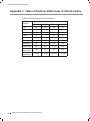
Appendix C Table of Funtion Differences of Switch Family.
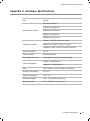
Appendix D Hardware Specifications.
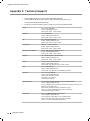
Appendix E Technical Support.
II
Related Document
Audience
This User Guide is for:
Network Engineer
Network Administrator
Conventions
Due to the similarity in structure of TL-SL2210WEB/TL-SL2218WEB/TL-SL2428WEB/
TL-SL2452WEB Gigabit Uplink Web Smart Switch series, in this User Guide we
take TL-SL2210WEB as an example to illustrate Chapter 2 Installation, Chapter 3
Lightning Protection, Chapter 4 Connection and Chapter 6 WEB Management.
This Guide uses the specific formats to highlight special messages. The following
table lists the notice icons that are used throughout this guide.
Remind to be careful. A caution indicates a potential which may result in
device damage.
Remind to take notice. The note contains the helpful information for a
better use of the product.
Remind to get further information. The further information provides you
more details about the product.
Audience
III
Contents
Chapter 1
Introduction ——————————————— 01
1.1
Product Overview ............................................................................................ 01
1.2
Features ............................................................................................................... 01
1.3
Appearance ........................................................................................................ 02
Chapter 2
Installation ———————————————— 05
2.1
Package Contents ............................................................................................ 05
2.2
Safety Precautions ........................................................................................... 05
2.3
Installation Tools............................................................................................... 08
2.4
Product Installation ......................................................................................... 08
Chapter 3
Lightning Protection ———————————— 10
3.1
Cabling Reasonably......................................................................................... 10
3.2
Connect to Ground.......................................................................................... 12
Chapter 4
Connection ——————————————— 13
4.1
Ethernet Port ..................................................................................................... 13
4.2
SFP Port ............................................................................................................... 13
4.3
Verify Installation ............................................................................................. 14
4.4
Power On............................................................................................................. 14
Chapter 5
Function Description ———————————— 15
5.1
System Setting .................................................................................................. 15
5.1.1
5.1.2
System Setting .......................................................................................... 15
File Transfer ................................................................................................ 15
5.1.3
5.1.4
5.2
Reboot & Reset.......................................................................................... 15
User ............................................................................................................... 15
Port Setting ........................................................................................................ 15
5.2.1
5.2.2
5.2.3
5.2.4
Port Parameter .......................................................................................... 15
Port Statistic and Port Status ............................................................... 16
Storm Control ............................................................................................ 16
Port Description ....................................................................................... 16
5.3
IV
Contents
Network Setting ............................................................................................... 17
5.3.1
5.3.2
Network Setting ....................................................................................... 17
Aging Time and Dynamic Address Table ......................................... 17
5.3.3
5.3.4
Static MAC Address Table ...................................................................... 18
Filtering MAC Address Table ................................................................ 18
5.3.5
5.3.6
5.4
5.4.1
Dynamic Binding...................................................................................... 18
Ping ............................................................................................................... 19
VLAN Setting ..................................................................................................... 19
VLAN Mode ................................................................................................ 19
5.5
Port Trunking ..................................................................................................... 20
5.6
Priority Setting .................................................................................................. 20
5.6.1
Priority Mode ............................................................................................. 20
5.6.2
5.6.3
5.6.4
5.7
Port-Based Priority ................................................................................... 20
Port Default Priority ................................................................................ 21
802.1p Priority ........................................................................................... 21
Port Mirroring .................................................................................................... 21
5.8
Virtual Cable Test .............................................................................................. 21
Chapter 6
WEB Management ————————————— 22
6.1
Overview ............................................................................................................. 22
6.2
Connecting to the Device ............................................................................. 22
6.2.1
6.2.2
6.3
Getting Started ......................................................................................... 22
Login the Switch....................................................................................... 25
Setting the Device ........................................................................................... 25
6.3.1
6.3.2
6.3.3
6.3.4
System Setting .......................................................................................... 28
Port Setting ................................................................................................ 30
Network Setting ....................................................................................... 35
VLAN Setting.............................................................................................. 41
6.3.5
6.3.6
6.3.7
6.3.8
Port Trunking ............................................................................................. 45
Priority Setting .......................................................................................... 46
Port Mirroring ............................................................................................ 48
Virtual Cable Test ...................................................................................... 49
Appendix A Troubleshooting ————————————— 50
Appendix B Table of Factory Defaults —————————— 51
Appendix C Table of Function Differences of Switch Family — 53
Appendix D Hardware Specifications —————————— 54
Appendix E Technical Support ————————————— 55
Contents
V
Gigabit Uplink Web Smart Switch
CCCCCCCCCC Introduction
1111
Product Overview
The TL-SL2210WEB/TL-SL2218WEB/TL-SL2428WEB/TL-SL2452WEB Gigabit Uplink Web
Smart Switch is compliant with the IEEE802.3 Ethernet protocols. The EIA-standardized
framework and smart configuration capacity can provide flexible solutions for variable
scale of networks.
This switch family is equipped with powerful management interface, via which system,
port, network, VLAN, truck and priority can be configured.
The TL-SL2210WEB/TL-SL2218WEB/TL-SL2428WEB/TLSL2452WEB Gigabit Uplink
Web Smart Switch provides 8/16/24/48 10/100Mbps Fast Ethernet ports, 1/1/2/2
10/100/1000Mbps Gigabit Ethernet ports and 1/1/2/2 SFP ports respectively, which
extends the connecting area and increases the networking flexibility.
1111 Features
¾¾ Compliant with IEEE802.3, IEEE802.3u, IEEE802.3ab and IEEE802.3z Standards
¾¾ IEEE 802.3x flow control for full-duplex
¾¾ Back pressure flow control for half-duplex
¾¾ Store-and-Forward switching method
¾¾ Support N-Way adaptive mode
¾¾ Support up 200 meters of Cat. 5 cables at the transmission speed of 10Mbps
¾¾ Support MAC address table of 8K entries
¾¾ Support MAC address learning and aging time
¾¾ Support port-based VLAN and IEEE802.1Q tag VLAN
¾¾ Support trunks
¾¾ Support management via WEB browser
¾¾ Support port-based priority and IEEE 802.1p priority
¾¾ Support static MAC address and filtering MAC address
¾¾ Support dynamic binding of MAC address
¾¾ Support port security, storm control and port monitoring
¾¾ Support virtual cable test
¾¾ Support static switch IP address and dynamic switch IP address through DHCP client
¾¾ Support system upgrading, configuration uploading and backup through TFTP server
01
Introduction
Gigabit Uplink Web Smart Switch
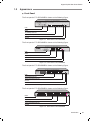
1111 Appearance
■■
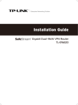
Front Panel
The front panel of TL-SL2210WEB is shown as the following figure.
R
TL-SL2210WEB
8+2G Web-Smart Switch
1
Link
Power
System
2
3
5
4
7
6
8
GIGA
SFP
Link/Act
Act
1
2
3
4
5
6
7
8
100M
1000M
Link/Act
RESET
GIGA
10/100Mbps
10/100/1000Mbps
1000Mbps
LEDs
RESET
10/100Mbps RJ45 Port
10/100/1000Mbps RJ45 Port
SFP Port
FFFFFFFFFFF Front Panel of TL-SL2210WEB
The front panel of TL-SL2218WEB is shown as the following figure.
R
TL-SL2218WEB
Power
16+2G Gigabit Web-Smart Switch
System
1
3
5
7
9
2
4
6
8
10 12 14 16
11 13 15
Link
Act
100Mbps
GIGA
1
3
5
7
9
11
13
15
2
4
6
8
10
12
14
16
GIGA
Link/Act
SFP
RESET
Link/Act
1000Mbps
LEDs
RESET
10/100Mbps RJ45 Port
10/100/1000Mbps RJ45 Port
SFP Port
FFFFFFFFFFF Front Panel of TL-SL2218WEB
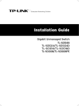
The front panel of TL-SL2428WEB is shown as the following figure.
Power
TL-SL2428WEB
Link
24+4G Gigabit Web-Smart Switch
Act
System
1
3
5
7
9
11
13
15
17
19
21
23
GIGA1
2
4
6
8
10
12
14
16
18
20
22
24
GIGA2
100M
1
3
5
7
9
11
13
15
17
19
21
23
GIGA1
2
4
6
8
10
12
14
16
18
20
22
24
GIGA2
SFP 1
SFP 2
SFP 1
Reset
1000M
SFP 2
LEDs
10/100Mbps RJ45 Port
10/100/1000Mbps RJ45 Port
SFP Port
Reset
FFFFFFFFFFF Front Panel of TL-SL2428WEB
The front panel of TL-SL2452WEB is shown as the following figure.
1
2
3
4
5
6
7
8
9
10
11
12
13
14
15
16
17
18
19
20
21
22
23
24
25
26
27
28
29
30
31
32
33
34
35
36
37
38
39
40
41
42
43
44
45
46
47
48
GIGA1 GIGA2
1
3
5
7
9
11
13
15
17
19
21
23
25
27
29
31
33
35
37
39
41
43
45
47
GIGA1
2
4
6
8
10
12
14
16
18
20
22
24
26
28
30
32
34
36
38
40
42
44
46
48
GIGA2
R
TL-SL2452WEB
48+4G Gigabit Web-Smart Switch
Power
SFP 1
RESET
System
RESET
SFP 2
Link/Act
SFP 1
SFP 2
LEDs
10/100Mbps RJ45 Port
10/100/1000Mbps RJ45 Port
SFP Port
FFFFFFFFFFF Front Panel of TL-SL2452WEB
Introduction
02
Gigabit Uplink Web Smart Switch
RESET
Press this button for three seconds to reset the software setting back to factory
default setting.
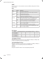
LEDs
LED
Power
System
Link/Act
100Mbps
1000Mbps
Status
Indication
On
The Switch is powered on
Off
The Switch is powered off or power supply is abnormal
On
The Switch works properly
Off
The Switch works improperly
On
A valid link is established on the port
Flashing
Data is being transmitted or received. (SFP port has Link/
Act LED only and must connect to 1000Mbps device.1
Off
No device is connected to the corresponding port
On
The corresponding port is running at 100Mbps
Off
There is no device linked to the corresponding port or the
port is running at 10Mbps
On
The corresponding port is running at 1000Mbps
Off
There is no device linked to the corresponding port or the
port is running at 100Mbps
Port Feature
Model
10/100Mbps RJ45 Port
10/100/1000Mbps RJ45 Port
SFP Port
TL-SL2210WEB
8
1
1
TL-SL2218WEB
16
1
1
TL-SL2428WEB
24
2
2
TL-SL2452WEB
48
2
2
10/100Mbps RJ45 Port
Designed to connect to the device with the bandwidth of 10Mbps or 100Mbps. Each
port has a corresponding Link/Act and 100Mbps LED.
10/100/1000Mbps RJ45 Port
Designed to connect to the device with the bandwidth of 10Mbps, 100Mbps or
1000Mbps. It has a corresponding Link/Act and 1000Mbps LED.
SFP Port
Designed to install SFP module. It has a corresponding Link/Act LED.
03
Introduction
Gigabit Uplink Web Smart Switch
■■
Rear Panel
The rear panel of TL-SL2210WEB/TL-SL2218WEB/TL-SL2428WEB/TL-SL2452WEB is
shown as the following figure.
Power Socket
FFFFFFFFFFF Rear Panel
Power Socket
Connect the female connector of the power cord here, and the male connector to
the AC power outlet. Please make sure the voltage of the power supply meets the
requirement of the input voltage.
Caution: Please use the provided power cord.
Introduction
04
Gigabit Uplink Web Smart Switch
CCCCCCCCCC Installation
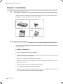
2222 Package Contents
Make sure that the package contains the following items. If any of the listed items is
damaged or missing, please contact your distributor.
One Gigabit Uplink Web Smart
Switch
One AC Power Cord
R
Power
System
TL-SL
2210W
Link
Act
100M
1
2
3
4
5
6
7
EB
Link/Act
8
1000M
GIGA
8+2G
1
Web-S
2
mart
Switch
3
4
5
RESET
10/100Mb
6
7
8
GIGA
SFP
ps
10/100/1000
Mbps
1000Mbps
Link/Act
This User Guide
Two Mounting Brackets and the
Fittings
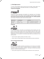
2222 Safety Precautions
To avoid any device damage and bodily injury caused by improper use, please observe
the following rules.
■■
Safety Precautions
■■
Keep the power off during the installation.
■■
■■
■■
Installation
Use only the power cord provided with the Switch.
Make sure that the supply voltage matches the specifications indicated on the rear
panel of the Switch.
■■
Ensure the vent hole is well ventilated and unblocked.
■■
Do not open or remove the cover of the Switch.
■■
05
Wear an ESD-preventive wrist strap, and make sure that the wrist strap has a good
skin contact and is well grounded.
Before cleaning the device, cut off the power supply. Do not clean it by the waterish
cloth, and never use any other liquid cleaning method.
Gigabit Uplink Web Smart Switch
Site Requirements
■■
To ensure normal eperation and long service life of the device, please install it in an
environment that meets the requirements described in the following subsection.
Temperature/Humidity
ȭ
ȭ
R
TL-SL2210WEB
8+2G Web-Smart Switch
1
2
3
5
4
7
6
8
GIGA
SFP
Link/Act
Power
Link
System
100M
Act
1
2
3
4
5
6
7
8
1000M
GIGA
Link/Act
RESET
10/100Mbps
10/100/1000Mbps
1000Mbps
Please keep a proper temperature and humidity in the equipment room. Too high/low
humidity may lead to bad insulation, electricity leakage, mechanical property changes
and corrosions. Too high temperature may accelerate aging of the insulation materials
and can thus significantly shorten the service life of the device. For normal temperature
and humidity of the device, please check the following table.
Environment
Temperature
Humidity
Operating
0℃ ~ 40℃
10% ~ 90%RH Non-condensing
Storage
-40℃ ~ 70℃
5% ~ 90%RH Non-condensing
Clearness
R
TL-SL2210WEB
8+2G Web-Smart Switch
1
Power
Link
System
100M
Act
2
3
5
4
7
6
8
GIGA
SFP
Link/Act
1
2
3
4
5
6
7
8
1000M
Link/Act
RESET
GIGA
10/100Mbps
10/100/1000Mbps
1000Mbps
The dust accumulated on the Switch can be absorbed by static electricity and result
in poor contact of metal contact points. Some measures have been taken for the
device to prevent static electricity, but too strong static electricity can cause deadly
damage to the electronic elements on the internal circuit board. To avoid the effect of
static electricity on the operation of the Switch, please attach much importance to the
following items:
■■
Dust the device regularly, and keep the indoor air clean.
■■
Keep the device well grounded and ensure static electricity has been transferred.
Electromagnetic Interference
R
TL-SL2210WEB
8+2G Web-Smart Switch
1
Power
Link
System
100M
Act
2
3
4
5
6
7
8
GIGA
SFP
Link/Act
1
2
3
4
5
6
7
8
1000M
GIGA
Link/Act
RESET
10/100Mbps
10/100/1000Mbps
1000Mbps
Electronic elements including capacitance and inductance on the device can be affected
by external interferences, such as conducted emission by capacitance coupling,
inductance coupling, and impedance coupling. To decrease the interferences, please
make sure to take the following measures:
■■
Use the power supply that can effectively filter interference from the power grid.
Installation
06
Gigabit Uplink Web Smart Switch
Keep the device far from high-frequency, strong-current devices, such as radio
transmitting station.
■■
Use electromagnetic shielding when necessary.
■■
Lightening Protection
R
TL-SL2210WEB
8+2G Web-Smart Switch
1
Power
Link
System
100M
Act
2
3
5
4
7
6
8
GIGA
SFP
Link/Act
1
2
3
4
5
6
7
8
1000M
GIGA
Link/Act
RESET
10/100Mbps
10/100/1000Mbps
1000Mbps
Extremely high voltage currents can be produced instantly when lightning occurs and the air
in the electric discharge path can be instantly heated up to 20,000℃. As this instant current
is strong enough to damage electronic devices, more effective lightning protection measures
should be taken.
■■
Ensure the rack and device are well earthed.
■■
Make sure the power socket has a good contact with the ground.
■■
Keep a reasonable cabling system and avoid induced lightning.
■■
Use the signal SPD (Surge Protective Device) when wiring outdoor.
Note: For detailed lightning protection measures, please refer to Chapter 3
Lightning Protection.
Installation Site
S
R
TL-SL2210WEB
8+2G Web-Smart Switch
1
Power
Link
System
100M
Act
2
3
4
5
6
7
8
GIGA
SFP
Link/Act
1
2
3
4
5
6
7
8
1000M
GIGA
Link/Act
RESET
10/100Mbps
10/100/1000Mbps
1000Mbps
When installing the device on a rack or a flat workbench, please note the following
items:
■■
■■
■■
07
Installation
The rack or workbench is flat and stable, and sturdy enough to support the weight
of 5.5kg at least.
The rack or workbench has a good ventilation system. The equipment room is well
ventilated.
The rack is well grounded. Keep the power socket less than 1.5 meters away from
the device.
Gigabit Uplink Web Smart Switch
2222 Installation Tools
■■
Phillips screwdriver
■■
ESD-preventive wrist wrap
■■
Cables
Note: These tools are not provided with our product. If needed, please self purchase
them.
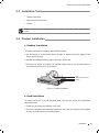
2222 Product Installation
■■
Desktop Installation
To install the device on the desktop, please follow the steps:
111Set the device on a flat surface strong enough to support the entire weight of the
device with all fittings.
222Remove the adhesive backing papers from the rubber feet.
333Turnover the device and attach the supplied rubber feet to the recessed areas on
the bottom at each corner of the device.
Feet
Bottom of the Device
Notch
000Mbps
1000M
bps
10/100/1
10/100
1000M
System
100M
Act
Power
1
2
3
4
5
6
7
8
Link/Ac
t
10WEB
Link
1
8+2G
2
Web -Sma
3
4
Link/Ac
t
Mbps
RESET
GIGA
5
6
7
8
GIGA
SFP
rt Swit
ch
TL-SL22
R
FFFFFFFFFFF Desktop Installation
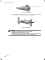
■■
Rack Installation
To install the device in an EIA standard-sized, 19-inch rack, follow the instructions
described below:
111Check the grounding and stability of the rack.
222Secure the supplied rack-mounting brackets to each side of the device with supplied
screws, as illustrated in the following figure.
Installation
08
Gigabit Uplink Web Smart Switch
Rack-mounting Bracket
Screw
R
Power
TL-SL221
0WEB
Link
Act
System
100M
1
2
3
4
5
6
7
8+2G
Link/Act
8
1
Web- Smar
2
t Switc
3
1000M
GIGA
h
4
5
6
7
RESET
10/100M
8
GIGA
SFP
bps
10/100/100
0Mbps
1000Mb
Link/Act
ps
FFFFFFFFFFF Bracket Installation
333After the brackets are attached to the device, use suitable screws (not provided) to
secure the brackets to the rack, as illustrated in the following figure.
Rack
R
Power
TL-SL221
0WEB
Link
Act
System
100M
1
2
3
4
5
6
7
Link/Act
8
1000M
GIGA
8+2G
1
Web- Smar
2
t Switc
3
h
4
5
RESET
10/100M
6
7
8
GIGA
SFP
bps
10/100/100
0Mbps
1000Mb
Link/Act
ps
FFFFFFFFFFF Rack Installation
Caution:
Please set 5~10cm gaps around the device for air circulation.
Please avoid any heavy thing placed on the device.
Please mount devices in sequence from the bottom to top of the rack and ensure a
certain clearance between devices for the purpose of heat dissipation.
■■
■■
■■
09
Installation
Gigabit Uplink Web Smart Switch
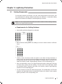
CCCCCCCCCC Lightning Protection
3333 Cabling Reasonably
In the actual network environment, you may need cable outdoors and indoors, and
the requirements for cabling outdoors and indoors are different. A reasonable cabling
system can decrease the damage of induced lightning to devices.
Note: It's not recommended using Ethernet cables outdoors. When cabling outdoors,
please use a signal lightning arrester.
■■
Requirements for Cabling Outdoors
■■
Aerial cabling without safeguard is not allowed.
■■
■■
■■
■■
It’s not allowed cabling down the building to connect network devices in different
floors.
Outdoor cables should be buried and paved to the indoor through basement. A
piece of steel wire should be paved underground along the pipe and connected to
the lightning protection terminal of the building for shielding. Before connecting the
cable to the device, install a signal lightning arrester on the corresponding port.
When an aerial cable is set up, the cable should be through a metal pipe (15m long
at least) before coming into the building. The two ends of this metal pipe should
be grounded. Before connecting the cable to the device, install a signal lightning
arrester on the corresponding port.
It’s not necessary to pave STP cables through pipes. The shielded layer of STP cable
should be well grounded. Before connecting the cable to the device, install a signal
lightning arrester on the corresponding port.
Lightning Protection
10
Gigabit Uplink Web Smart Switch
■■
Requirements for Cabling Indoors
When cabling indoors, keep a certain distance away from the devices that may cause
high-frequency interferences, such as down-conductor cable, powerline, power
transformer and electromotor.
■■
■■
The main cable should be paved in the metal raceway of the access shaft. When
cabling, keep the loop area formed by the cable itself as small as possible.
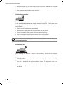
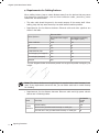
Requirements for the distance between Ethernet cable and other pipelines are
shown in the table.
Ethernet Cable
Other Pipelines
Min Parallel Net Length L
(mm1
Min Parallel-overlapping
Net Height H (mm1
Down-conductor
1000
300
PE
50
20
Service pipe
150
20
Compressed air pipe
150
20
Thermal pipe (not wrapped1
500
500
Thermal pipe (wrapped1
300
300
Gas pipe
300
20
The two diagrams below demonstrate parallel net length and parallel-overlapping net
height.
Note: The above minimum net length/height is required when metal raceway is not
used. If any requirements cannot be met, you can add a steel tube or metal raceway
for shielding.
■■
11
Requirements for the distance between Ethernet cable and high-power electric
devices are in following tables.
Min Parallel
Length
(mm1
Cable
Pave Way
<2kVA
powerline
Parallel cabling
130
One is in the grounded metal raceway or metal pipe
70
The both are in the grounded metal raceway or metal pipe
10
Lightning Protection
Gigabit Uplink Web Smart Switch
2~5kVA
powerline
Parallel cabling
300
One is in the grounded metal raceway or metal pipe
150
The both are in the grounded metal raceway or metal pipe
80
>5kVA
powerline
Parallel cabling
600
One is in the grounded metal raceway or metal pipe
300
The both are in the grounded metal raceway or metal pipe
150
Device
Min Distance (m1
Switch case
1.00
Transformer room
2.00
Elevator tower
2.00
Air-conditioner room
2.00
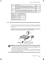
3.2 Connect to Ground
Connecting the device to ground is to quickly release the lightning over-voltage and
over-current of the device, which is also a necessary measure to protect the body from
electric shock.
In different environments, the device may be grounded differently. If the device is
installed in the normal environment, the device can be grounded via the PE (Protecting
Earth) cable of the AC power supply as shown in the following figure.
FFFFFFFFFFF Connecting to the Ground
Note:
The figure is to illustrate the application and principle. The power plug you get from
the package and the socket in your situation will comply with the regulation in your
country, so they may differ from the figure above.
If you intend to connect the device to the ground via the PE (Protecting Earth) cable
of AC power cord, please make sure the PE (Protecting Earth) cable in the electrical
outlet is well grounded in advance.
■■
■■
Lightning Protection
12
Gigabit Uplink Web Smart Switch
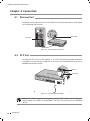
CCCCCCCCCC Connection
4444 Ethernet Port
Please connect the Ethernet port of the Switch to the network devices by RJ45 cables
as the following figure shown.
TL-SL2
210W
6
7
EB
Link/A
8
8+ 2G
W eb -S
1
ct
1000M
GIGA
RE SE
RJ45 Cable
T
RJ45 Port
R
Power
System
TL-SL221
0WEB
Link
Act
1
100M
2
3
4
5
6
7
8+2G
Link/Act
8
Web-
1
Smar
2
1000M
GIGA
t Switc
3
h
4
5
RESET
10/100M
6
7
8
GIGA
SFP
bps
10/100/10
00Mbps
1000Mb
ps
Link/Act
FFFFFFFFFFF Connecting the RJ45 Port
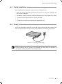
4444 SFP Port
Connect the SFP port to a SFP module. If an SFP transceiver(purchased separately)
is installed in a slot and has a valid link on the port, the associated RJ45 port will be
disabled and cannot be used.
8
GI GA
SF P
SFP Port
10/100
/1000M
bps
10 00 Mb
ps
Link/A
ct
SFP Module
R
Pow er
Syst em
TL-SL2
210W
Link
Act
100M
1
2
3
4
5
6
7
EB
Link/ Act
8
1000M
GIGA
8+2 G
1
We b-S
2
ma rt
Sw itc
3
h
4
5
RES ET
10/1 00M
6
7
8
GIG A
SFP
bps
10/100/100
0Mbps
1000 Mbp
s
Link/ Act
FFFFFFFFFFF Inserting the SFP Module
Note: SFP module supports hot-plugging, plug the SFP module into the SFP port
and the switch can identify it automatically. The SFP port must connect to 1000Mbps
device.
13
Connection
Gigabit Uplink Web Smart Switch
4444 Verify Installation
After completing the installation, please verify the following items:
■■
There are 5~10cm of clearance around the sides of the device for ventilation and
the air flow is adequate.
■■
The voltage of the power supply meets the requirement of the input voltage of the device.
■■
The power socket, device and rack are well grounded.
■■
The device is correctly connected to other network devices.
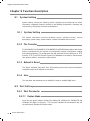
4444 Power On
Plug in the negative connector of the provided power cord into the power socket of the
device, and the positive connector into a power outlet as the following figure shown.
FFFFFFFFFFF Connecting to Power Supply
Note: The figure is to illustrate the application and principle. The power plug you get
from the package and the socket in your situation will comply with the regulation in
your country, so they may differ from the figure above.
Connection
14
Gigabit Uplink Web Smart Switch
CCCCCCCCCC Function Description
5555 System Setting
System setting contains the following topics: displaying and configuring the switch
information, upgrading firmware, backing up and loading configuration, rebooting and
soft-resetting, configuring username and password.
555555 System Setting
The system information contains hardware version, software version, system
description, system name, system location, contact information and run time.
555555 File Transfer
TL-SL2210WEB/TL-SL2218WEB/TL-SL2428WEB/TLSL2452WEB Gigabit Uplink Web Smart
Switch is equipped with the function of configuration backup, configuration loading
and system upgrading. The configuration file and executive file are transferred in TFTP
protocol. TFTP (Trivial File Transfer Protocol) is dedicated to transferring files between
two network stations. It’s based on UDP protocol.
555555 Reboot & Reset
The “Reset” indicates “Soft-reset” here. Soft-resetting restores the switch configuration
to default except the IP address of the switch.
555555 User
The username and password can be modified in order to exclude illegal users.
5555 Port Setting
555555 Port Parameter
55555555 Duplex Mode
Ports have the duplex modes: 10Mbps HD, 10Mbps FD, 100Mbps HD, 100Mbps FD and
1000Mbps FD (Giga port support). The First part indicates the transmission rate and
the second part indicates the duplex mode.
15
Fuction Description
Gigabit Uplink Web Smart Switch
¾¾ HD: half-duplex, the port supports transmission between the device and the client
in only one direction at a time.
¾¾ FD: full-duplex, the port supports transmission between the device and its link
partner in both directions simultaneously.
Auto negotiation is a protocol between two link partners that enables a port to
advertise its transmission rate and duplex mode to its partner.
55555555 Flow Control
Flow control enables lower speed devices to communicate with higher speed devices.
This is implemented by the higher speed device refraining from sending packets.
55555555 Port Security
If the port security is enabled, it will not learn new MAC address and only transmit the
frames from the MAC address list in the port’s static MAC address table.
555555 Port Statistic and Port Status
Port Statistic calculates the statistics of each port, such as how many frames, error
frames, broadcast frames it has received and so on.
Port Status indicates whether the port is linked, not linked or disabled, what speed and
duplex mode it is working on, and whether flow control is enabled or disabled.
555555 Storm Control
Storm control limits the amount of multicast, broadcast and UL (the address hasn't
been learned) frames accepted and forwarded by the device. When Layer 2 frames are
forwarded, broadcast, multicast and UL frames are flooded to all ports on the relevant
VLAN. This occupies bandwidth, and loads all nodes on all ports.
A Storm is a result of an excessive amount of these frames simultaneously transmitted
across a network by a single port. Forwarded message responses are heaped onto the
network, straining network resources or causing the network to time out. Storm control
is enabled for all ports by defining the packet type and the rate at which the packets
are transmitted. The system measures the incoming defined frame rates on each port,
and discards the frames when the rate exceeds a user-defined rate.
555555 Port Description
Use a description word to indicate the port.
Fuction Description
16
Gigabit Uplink Web Smart Switch
5555 Network Setting
The network module provides the function of setting the switch's IP address, dynamic
binding and aging time, configuring static MAC address and filtering MAC address,
displaying dynamic bound address and ping.
555555 Network Setting
An IP address is indispensable for a switch to be accessed. The TL-SL2210WEB/TLSL2218WEB/TL-SL2428WEB/TLSL2452WEB Gigabit Uplink Web Smart Switch provides
the configuration interface of IP address, netmask and default gateway.
DHCP (Dynamic Host Configuration Protocol) is dedicated for the DHCP client to obtain
IP configuration information from the DHCP server. Two types of information are
included in IP configuration information. One type is specific configuration information,
the other is IP address parameter. DHCP is based on client-server mode. The network
station that offers the IP configuration information is called DHCP server.
Make sure that a DHCP server is correctly connected to the network so as to activate
the DHCP client function of the switch firstly, then the switch will automatically obtain
IP address, netmask and default gateway from the DHCP server.
If more than one DHCP servers are available in the network, the switch will choose one
according to a specific algorithm.
Note: If no DHCP server is present in the network, the DHCP client fails to get IP
configuration information, the switch then restores the IP parameters to default in
several minutes to ensure a valid IP address being equipped.
555555 Aging Time and Dynamic Address Table
A dynamic MAC address table is maintained inside the switch. MAC address is the
physical address of a network device; it is six-bytes long and should be within in a
subnet. A network device can be identified by its MAC address.
A dynamic address table entry contains two items: MAC address and its corresponding
switch port. The dynamic address table is volatile. The dynamic address entry begins
to age once it has been added; it will be purged if it isn’t renewed in a specified length
of time, which is defined as aging time.
The aging time ranges from 0 to 3825 seconds for this switch family.
The default value is 300 seconds. Dynamic address table entry won’t age if 0 is set.
The aging time precision is 15 seconds.
17
Fuction Description
Gigabit Uplink Web Smart Switch
555555 Static MAC Address Table
A static MAC address table entry contains a MAC address and its corresponding switch
port. All the packets taking that MAC address as their destination will be forwarded to
the corresponding switch port.
The static MAC address won’t age, which differs from the dynamic MAC address. The
static MAC address table entry is always valid before it is deleted.
Supposing an entry, whose MAC address is 000AEB000001 and corresponding port
number is 1 and it is added to the static MAC address table. All the packets routing to
the address of 000AEB000001 egress for the switch port 1. This static entry obliges
the device of 000AEB000001 to be connected to port 1; otherwise, that device cannot
be accessed. Static MAC addresses are free of MAC learning, which enhances the
efficiency of packets forwarding. The MAC addresses already configured in static MAC
address table cannot be added to filtering MAC address table.
The capacity of static MAC address table capacity differs among different switches.
Appendix C lists the difference.
555555 Filtering MAC Address Table
A filtering MAC address excludes a device from being accessed through the switch. All
the packets taking the filtering MAC address as their destination will be discarded. The
filtering MAC address is applicable to all the switch ports. The configured filtering MAC
address can neither be added to static MAC address table, nor be bound by switch
ports.
555555 Dynamic Binding
A switch port in dynamic binding state can bind a specified number of MAC address.
Once the specified number is reached, the port transfers into secure state automatically
and stops binding MAC addresses. The bound MAC addresses won’t age, they can be
removed by disabling the dynamic binding or rebooting the switch.
The function of dynamic binding causes the switch port to acknowledge the devices
connecting to it after startup, and stores the connections (through binding MAC
addresses) in static state. This enhances the efficiency of packets forwarding and limits
the connecting device number of the switch port. Reboot the switch after configuring
the dynamic binding function. The switch will acknowledge and bind the latest
connecting devices. If the switch is managed through remote connection, please add
the MAC address of the management computer or that of the default gateway to the
static MAC address table; otherwise, the management channel may break down.
Fuction Description
18
Gigabit Uplink Web Smart Switch
555555 Ping
The ping function is to test the connectedness of the link between the switch and
destination.
5555 VLAN Setting
VLANs are logical subgroups with a Local Area Network (LAN) that combine user
stations and network devices into a single unit, regardless of the physical LAN segment
to which they are attached. VLANs allow network traffic to flow more efficiently within
subgroups.
VLANs use software to reduce the amount of time it takes for network changes,
additions, and moves to be implemented.
VLANs can be created per unit, per device, or through any other logical connection
combination, since they are software-based and not defined by physical attributes.
VLANs function at Layer 2. Since VLANs isolate traffic within the VLAN, a Layer 3 router
working at a protocol level is required to allow traffic flow between VLANs. Layer
3 routers identify segments and coordinate with VLANs. VLANs are Broadcast and
Multicast domains. Broadcast and Multicast traffic is transmitted only in the VLAN in
which the traffic is generated.
555555 VLAN Mode
There are 3 types of VLAN mode supporting in the switch:
1) Port VLAN
VLANs are divided based on ports.
2) IEEE802.1Q Tag VLAN
The IEEE802.1Q protocol defines a new format of the frame. It adds a tag header in
the original Ethernet frame, as follows:
FFFFFFFFFFF IEEE802.1Q frame
19
Fuction Description
Gigabit Uplink Web Smart Switch
IEEE802.1Q Tag VLAN is divided by VLAN ID (VID). When receiving a frame, the switch
checks the VID in the tag header of the frame to decide which VLAN it belongs to. If
the receiving frame doesn’t contain the tag header, the switch will assign a tag to the
frame, using the PVID of the port as its VID.
3) MTU VLAN
MTU VLAN(Multi-Tenant Unit VLAN) defines an uplink port. The uplink port will build up
several VLANs with each of the other ports. Each VLAN contains two ports-the uplink
port and one of the other ports in the switch, so the uplink port can communicate with
any other port but other ports can’t communicate with each other.
5555 Port Trunking
Trunk is Link Aggregation. It optimizes port usage by linking a group of ports together
to form a single trunk (aggregated groups). Bandwidth of the Trunk is the sum of
bandwidth of its member ports. There are some rules on using Trunk:
1) Before setting the Trunk, its member ports should be divided to the same VLAN, and
have the same PVID and drop untagged frame rule. Change of the Trunk setting will
not affect the VLAN setting. Trunks can not be set if the switch is in MTU VLAN mode
2) The Trunk member ports can’t enable port security and can’t be set as mirror or
mirrored port.
3) All of the Trunk member ports should be connected correctly; otherwise some ports
will not be able to work.
5555 Priority Setting
555555 Priority Mode
Three priority modes (disable, port-based and IEEE802.1p) are provided for this switch
family.
The priority rule can be set to be“Weighted” or “Fixed”. When priority rule is configured
as "weighted", a 1,2,4,8 weighting is applied to forward packets. When "fixed" is
selected, all packets with top priority egress for a switch port until that priority's queue
is empty, then the packets with next lower priority.
555555 Port-Based Priority
Four priority classes (lowest, lower, higher and highest) are available for a switch port
in port-based priority mode. The priority class of the port is applied to all the packets
entering from the port.
Fuction Description
20
Gigabit Uplink Web Smart Switch
555555 Port Default Priority
If IEEE802.1p priority mode is configured, when a switch port receives an untagged
frame (a frame without priority tag), the port's default priority tag will be inserted into
the frame before any other process.
555555 802.1p Priority
In IEEE802.1p priority mode, all packets are classified into four priority classes (lowest,
lower, higher and highest) according to the embedded priority tag. If an untagged
frame is received, the default priority tag of the port will be attached.
5555 Port Mirroring
Port mirroring monitors and mirrors network traffic by forwarding copies of incoming
and outgoing packets from one port to a monitoring port. Port mirroring enables switch
performs monitoring.
Network administrators can configure port mirroring by selecting a specific port from
which to copy all packets, and other ports to which the packets copied.
5555 Virtual Cable Test
The virtual cable test feature uses Time Domain Reflectometry (TDR) to test the
quality of the cables connected to the port. Some of the possible problems then can
be diagnosed include opens, shorts, cable impedance mismatch, bad connectors,
termination mismatch, and bad magnetics. It can also test the distance to the problem
location, with the precision of ±1 meter.
21
Fuction Description
Gigabit Uplink Web Smart Switch
CCCCCCCCCC WEB Management
6666 Overview
The Gigabit Uplink Web Smart Switch is managed via WEB pages. The smart and
friendly interfaces make the switch management an easy job.
6666 Connecting to the Device
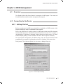
666666 Getting Started
Before connecting to the WEB server (switch), the installation of WEB browser, which
supports JavaScript, must be completed in the computer.
Due to the difference of parsing syntax, the WEB page shows may differ between
variable WEB browsers. Microsoft Internet Explorer of version 5.0 or higher is
recommended. If Netscape is selected, please ensure the latest version. To obtain
excellent display quality, a screen resolution of 1024 x 768 or higher is necessary.
The appropriate configuration of WEB browser must be ensured before switch
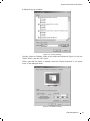
management. An example of configuration using IE on Windows XP is given below.
Firstly, select “Tool->Internet Options” on the menu, a dialog will pop up:
FFFFFFFFFFF Internet Options Dialog
Web Management
22
Gigabit Uplink Web Smart Switch
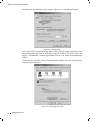
Secondly, click the “Settings” button hinted in Figure 6-1, a new dialog will appear:
FFFFFFFFFFF Settings Dialog
In the case of IE5.0, please check the option “Every visit to the page”; otherwise, some
wrong information may show in WEB pages. If the IE version is 6.0, “Every visit to the
page” or “Automatically” are both appropriate. Click the “OK” button and complete this
setting.
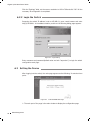
Thirdly, click the “Security” label of “Internet Options” dialog; press the “Custom Level”
button hinted in Figure 6-3.
FFFFFFFFFFF Internet Options Dialog
23
Web Management
Gigabit Uplink Web Smart Switch
A dialog will pop up as below.
FFFFFFFFFFF Security Settings
Fourthly, Select the “Medium” option of the combo box indicated in Figure 6-4, click the
“Reset” button, and click “OK” to quit.
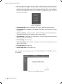
Fifthly, right-click the mouse on desktop, select the “Display Properties” in the popup
menu, a new dialog will show:
FFFFFFFFFFF Resolution Setting
Web Management
24
Gigabit Uplink Web Smart Switch
Click the “Settings” label, set the screen resolution to 1024 x 768 and click “OK”. All the
necessary IE configuration is completed.
666666 Login the Switch
Supposing the switch IP address is set as 192.168.0.1, open a web browser and enter
http://192.168.0.1 in the address location, and then the following dialog page appears:
FFFFFFFFFFF Login Dialog
Enter username and password (default value are both "supervisor") to login the switch
configuration main page.
6666 Setting the Device
After logging into the switch, the main page appears as the following. It contains three
parts:
FFFFFFFFFFF TL-SL2210WEB Main Page
111The main part of the page is the main window to display the configuration page.
25
Web Management
Gigabit Uplink Web Smart Switch
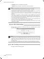
222The Port LED Indicator table lies at the top of the page. It provides a visual
representation of the ports on the switch front panel to display the status of the
ports. The ports, signed with number are the normal ports, signed with GIGA are the
Giga ports, signed with SFP are the SFP ports. The green icon indicates that the port
is linked; the gray icon indicates that the port is not linked; a gray icon with a black
bar indicates that the port is disabled; for the SFP port, a blue icon indicates that the
SFP module hasn’t been installed.
FFFFFFFFFFF Port LED Indicator Table (SFP uninstalled)
FFFFFFFFFFF Port LED Indicator Table (SFP installed)
Click on the icon of the port to open a new window, which shows the details of the port,
as shown below:
FFFFFFFFFFFFPort Status Table
FFFFFFFFFFFFSFP Status Table (uninstalled)
FFFFFFFFFFFFSFP Status Table (installed)
Web Management
26
Gigabit Uplink Web Smart Switch
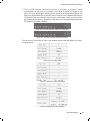
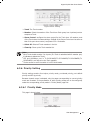
333On the left side of the page is the menu table. It contains 8 main menus. Each menu
has some submenus. Click on a menu, it will open its submenu and the main window
displays the configuration page of the submenu list first. Click on the submenu
you want to configure to open the corresponding configuration page. The menu
structure is as follows:
FFFFFFFFFFFFMain Menu
¾¾ System Setting: System Information, File Transfer, Reboot & Reset, and User.
¾¾ Port Setting: Port Parameter, Port Statistic, Port Status, Storm Control, and Port
Description.
¾¾ Network Setting: Switch IP Address, Static MAC Address, Filtering MAC Address,
Dynamic Binding, Bound MAC Address, Aging Time, and Ping.
¾¾ VLAN Setting: VLAN Mode, Port VLAN Setting, Tag VLAN Global Setting, Tag VLAN
Setting, and MTU VLAN Setting.
¾¾ Port Trunking: Port Trunking.
¾¾ Priority Setting: Priority Mode, Port-Based Priority, Port Default Priority, and
802.1p Priority Class.
¾¾ Port Mirroring: Port Mirroring.
¾¾ Virtual Cable Test: Virtual Cable Test.
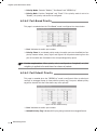
The following shows the main page of the TL-SL2218WEB, TL-SL2428WEB and TLSL2452WEB:
FFFFFFFFFFFFTL-SL2218WEB Main Page
27
Web Management
Gigabit Uplink Web Smart Switch
FFFFFFFFFFFFTL-SL2428WEB Main Page
FFFFFFFFFFFFTL-SL2452WEB Main Page
666666 System Setting
System setting contains four topics: system information, file transfer, reboot & reset
and user.
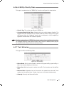
66666666 System Information
This page contains the following fields:
FFFFFFFFFFFFSystem Information
Web Management
28
Gigabit Uplink Web Smart Switch
¾¾ Software Version: Displays the installed software version number.
¾¾ Hardware Version: Displays the installed device hardware version number.
¾¾ System Description: Displays the device model number and name.
¾¾ System Name: Defines the user-defined device name.
¾¾ System Location: Defines the location where the system is currently running.
¾¾ Contact Information: Defines the contact information of switch manager.
¾¾ Run time: Shows the run time since last startup.
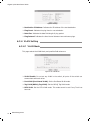
66666666 File Transfer
This page contains the following fields:
FFFFFFFFFFFFFile Transfer
¾¾ Transfer Type: Lists three types of file transfer supported by the switch.
¾¾ File Name: Identifies the file to be loaded or to be backed up on TFTP server.
¾¾ TFTP Server IP: Indicates the IP address of TFTP server.
Further explanation:
File transfer types:
■■
■■
■■
System Upgrading: Means downloading the executable file from TFTP server to
switch and upgrading the system.
Configuration Backup: Means backing up the current configuration of the switch to
TFTP server.
Configuration Loading: Means downloading the configuration from TFTP server to the
switch and update it.
Caution:
Please make sure the target file exits on TFTP server before downloading.
Please make sure the TFTP server is in operation.
Breaks should be avoided during file transfer; otherwise, the switch may get
damaged.
■■
■■
■■
29
Web Management
Gigabit Uplink Web Smart Switch
66666666 Reboot & Reset
This page is shown as below.
FFFFFFFFFFFFReboot & Reset
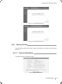
A prompt is displayed if a button is pressed. For example, if the button “Soft-reset” is
pressed, a message box will be activated as shown in Figure 6-20.
FFFFFFFFFFFFMessage Box
66666666 User
This page provides the interface of configuring username and password.
FFFFFFFFFFFFUser Configuration
You are suggested to retype the new password in "Confirm new password" box instead
of copying in order to avoid typing mistakes.
Note:
Only letters, numbers and punctuations can be input into username and password
field, the other characters are considered illegal. The length of username and
password ranges from 1 to 16 characters.
The initial username and password is supervisor/supervisor.
■■
■■
666666 Port Setting
Web Management
30
Gigabit Uplink Web Smart Switch
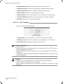
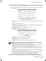
66666666 Port Parameter
This page contains the following fields:
FFFFFFFFFFFF Port Parameter
¾¾ Port Status: Indicates whether the port is operational or non-operational. "Enable"
indicates the port is operational and "Disable" indicates the port is non-operational.
If a port is unused for a long time, it can be set to be non-operational to cut down
energy costs.
Note: You can't manage the switch via the port, which is non-operational. Please set
the value of the management port to be “enable”.
¾¾ Port Security: "Enable" indicates the port will not learn new MAC address and only
transmits the frames from the MAC address it has learned. "Disable" indicates it will
learn new MAC address.
Caution: If you haven’t set the static MAC address, you can't enable all of the port
security, which will result in an inability to manage the switch.
¾¾ Flow Control: Indicates whether the flow control is enabled or disabled.
¾¾ Duplex Mode: Possible field values are Auto, 10Mbps HD, 10Mbps FD, 100Mbps
HD, 100Mbps FD and 1000Mbps FD (Giga port support), "HD" stands for halfduplex
and "FD" stands for full-duplex. “Auto” means auto negotiation.
Further explanation:
By operating on fields in the All Ports line expediently, you can set the values of all
ports in the corresponding field. Some other setting pages offer the same function.
Parameters of Trunk member ports are configured with default value (see the
Appendix B table) and cannot be configured here (see port 5 and 6 in the Figure
6-22 for example). For SFP, the Duplex Mode is set to “1000Mbps FD” and cannot be
modified.
■■
■■
31
Web Management
Gigabit Uplink Web Smart Switch
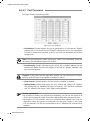
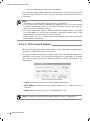
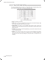
66666666 Port Statistic
This page displays the port statistic and it contains the following entries:
FFFFFFFFFFFFPort Statistic
¾¾ Tx Collisions: The number of collision events experienced by the port. This counter
is applicable in half-duplex only.
¾¾ Tx Ucast: The number of frames sent that have a unicast destination MAC address.
¾¾ Tx Mcast: The number of frames sent that have a multicast destination MAC
address.
¾¾ Tx Bcast: The number of frames sent that have a broadcast destination MAC
address.
¾¾ Rx (G Pkts): The number of good frames received.
¾¾ Rx Ucast: The number of frames received that have a unicast destination MAC
address.
¾¾ Rx Mcast: The number of frames received that have a multicast destination MAC
address.
¾¾ Rx Bcast: The number of frames received that have a broadcast destination MAC
address.
¾¾ Rx (B Bytes): The sum of bytes of frames received with an invalid length. The
frames with the length more than 1522 octets are counted as 1522 octets ones.
¾¾ Rx UnderSz: Total frames received with a length of less than 64 octets but with a
valid FCS.
¾¾ Rx OverSize: Total frames received with a length of more than max size octets but
with a valid FCS.
¾¾ Rx Jabber: Total frames received with a length of more than max size octets but
with an invalid FCS.
¾¾ RX64 B: Total frames received with a length of exactly 64 octets, including those
with errors.
¾¾ RX 65 to 127 B: Total frames received with a length of between 65 and 127 octets
inclusive, including those with errors.
Web Management
32
Gigabit Uplink Web Smart Switch
¾¾ RX 128 to 255 B: Total frames received with a length of between 128 and 255
octets inclusive, including those with errors.
¾¾ RX 256 to 511 B: Total frames received with a length of between 256 and 511
octets inclusive, including those with errors.
¾¾ RX 512 to 1023 B: Total frames received with a length of between 512 and 1023
octets inclusive, including those with errors.
¾¾ RX Bytes: The sum of bytes of frames received, not including those with errors.
Note: Each statistic counter has the max numerical value of about 1.8e+19, in
excess of this value, the counter will be reset to zero. You can also click on the
“Reset” button to reset all of the statistic counters to zero.
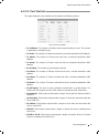
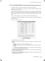
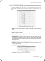
66666666 Port Status
This page displays the port status and it contains the following fields:
FFFFFFFFFFFFPort Status
¾¾ Port Status: Indicates whether the port is linked, not linked, or disabled.
¾¾ Speed (Mbps): Indicates the port speed with the unit of Mbps.
¾¾ Duplex Mode: Indicates the port is in duplex mode.
¾¾ Flow Control: Indicates whether flow control of the port is enable or disable.
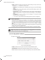
66666666 Storm Control
This page contains the following fields:
33
Web Management
Gigabit Uplink Web Smart Switch
FFFFFFFFFFFFStorm Control
¾¾ Broadcast Control: Enable or disable the broadcast control to limit the broadcast
frames.
¾¾ Multicast Control: Enable or disable the multicast control to limit the multicast
frames. Enabling multicast control will also enable broadcast control.
¾¾ UL Control: Enable or disable the UL control to limit the UL packets. Enabling UL
control will also enable broadcast control and multicast control.
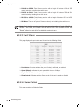
¾¾ Limit Rate: Indicates the maximum rate (kilobytes per second) at which the
controlled packets configured above are forwarded. For the 1000Mbps port, if set
the value of 64Kbps, the actual value is about 70Kbps.
Note: Parameters of Trunk member ports display the parameters of the Trunk
they belong to and it cannot be configured here (see port 5 and 6 in Figure 6-25
for example). You can configure parameters of the Trunk in the “Port Trunking”
page.
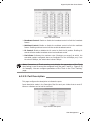
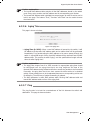
66666666 Port Description
This page configures the description to indicate the ports.
Input description words in the Description filed for each port. Notice that at most 15
letters or numbers can be held in each field.
FFFFFFFFFFFFPort Description
Web Management
34
Gigabit Uplink Web Smart Switch
666666 Network Setting
This page contains the following topics: switch IP address, static MAC address, filtering
MAC address, dynamic binding, bound MAC address, aging time and ping.
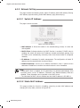
66666666 Switch IP Address
This page is shown as below:
FFFFFFFFFFFFSwitch IP Address
¾¾ MAC Address: Is firmed into switch in the manufacturing process; it is sole and
unchangeable.
¾¾ DHCP Client: Indicates whether the DHCP function is enabled. If DHCP client is
enabled, the switch will obtain the IP address, netmask and default gateway from
the DHCP server automatically; otherwise, these three items should be configured
manually.
¾¾ IP Address: Is necessary for switch management. The configuration of switch IP
address must be compliant with the subnet layout.
¾¾ Default Gateway: Serves as the default destination when a packet whose
destination IP address is not within the switch’s subnet is to be forwarded.
Note:
When DHCP client is enabled, the IP parameters are obtained automatically from
the DHCP server, so the “IP Address”, “Netmask” and “Default Gateway” fields are
disabled. These parameters can be queried on the DHCP server.
The initial state of DHCP client is disabled and the initial IP address is 192.168.0.1.
■■
■■
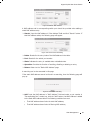
66666666 Static MAC Address
This page provides the function of adding, searching a static MAC address and
changing the entry state, as shown in Figure 6-28.
35
Web Management
Gigabit Uplink Web Smart Switch
FFFFFFFFFFFFStatic MAC address
A MAC address and its corresponding switch port should be provided when adding a
static MAC address entry.
¾¾ Search: Input the MAC address in “Mac Address” field and click “Search” button. If
that MAC address exists, the following page will appear:
FFFFFFFFFFFFA Successful Searching
¾¾ Index: Stands for the entry index of the MAC address in the table.
¾¾ Port: Stands for the switch port number.
¾¾ State: Indicates the entry in enabled state or disabled state.
¾¾ Operation: Provides the function of enabling, disabling or deleting an entry.
¾¾ Return: Return to the “Static MAC Address” page.
A searching can be also executed in this page.
If the static MAC address cannot be found in a searching, then the following page will
pop up:
FFFFFFFFFFFFA Failed Searching
¾¾ Add: Input the MAC address in “MAC Address” field and select a port number in
“Corresponding Port” combo box, click the “Add” button, that MAC address is added
to the static MAC address table if the following conditions are met:
■■
That MAC address doesn’t exist in static MAC address;
■■
That MAC address doesn’t exist in filtering MAC address;
Web Management
36
Gigabit Uplink Web Smart Switch
■■
There is enough space in static MAC address table.
The static MAC address table is divided into several pages. At most 10 entries can be
held in one page. The buttons “First”, “Previous” and “Next” can be used to browse the
whole table.
Note:
The capacity of the static MAC address is shown in “Appendix C”.
If an incorrect port number is selected when adding an entry, or the port number
is modified unexpectedly later, then the entries must be renewed; otherwise, the
packets cannot be forwarded correctly.
If a device, whose MAC address is added to static MAC address table, is connected
to a wrong switch port (not the port configured in static MAC address entry), all the
packets routing to the device cannot reach the device.
A MAC address cannot be added to static MAC address table and filtering MAC
address table simultaneously.
■■
■■
■■
■■
66666666 Filtering MAC Address
All the packets taking the filtering MAC address as their destination are discarded by
the switch no matter which port they enter from.
This page provides the function of adding, searching a filtering MAC address and
changing the entry state. The filtering MAC address entry is applicable to all switch
ports. The operating instruments, which are similar to “Static MAC Address”, are
omitted here.
FFFFFFFFFFFFFiltering MAC Address
¾¾ Index: Indicates the entry index of filtering MAC address table.
¾¾ MAC Address: Indicates the filtering MAC address to be configured or to be
searched.
¾¾ State: Indicates whether the entry is in enabled state or not.
Note: The capacity of filtering MAC address table is shown in “Appendix C”.
37
Web Management
Gigabit Uplink Web Smart Switch
66666666 Dynamic Binding
This page provides the function of enabling or disabling dynamic binding.
If dynamic binding is disabled, the switch port learns MAC address unlimitedly (at most
8000 entries can be learned).
A switch port with dynamic binding enabled can bind a specified number of MAC
address. The MAC addresses bound by the switch port are always valid and won’t age.
If the specified number is reached, the port stops binding and transfers into secure
state.
The bound MAC addresses can be queried in the “Bound MAC Address“ page.
If the dynamic binding is disabled or the switch restarts, the bound MAC address
entries are cleared.
There are 5 items in this page:
FFFFFFFFFFFFDynamic Binding
¾¾ Port: Indicates switch port number.
¾¾ Binding: Three options of dynamic binding are available. The details are shown
below:
■■
■■
■■
Disable: Cause this port to learn MAC address freely.
Enable: Cause the port to bind MAC addresses until the specified number is
reached.
--: This option is available only if the port is in a secure state, when this option is
selected, the port state keeps unchanged.
¾¾ Number of MAC Address to Bind: Indicates the max number of MAC addresses
that one switch port can bind.
¾¾ Number of Bound MAC Address: Indicates the number of MAC addresses that
already bind to a switch port.
Web Management
38
Gigabit Uplink Web Smart Switch
¾¾ State: Indicates the switch port state that may be binding, free port, secure port,
unplugged or "--". The details are shown below:
■■
■■
■■
■■
■■
Free Port: The binding function is disabled, and the port can learn MAC address
freely.
Binding: The port is in binding state, and its bound MAC address number is still
less than the max number.
Secure Port: The port has already bound the max number of MAC address in
dynamic binding mode, or it was set to secure port manually in "Port Parameter"
page.
Unplugged: The port is a SFP port and unplugged. The dynamic binding
function cannot be configured now.
--: The port is a trunk member and its binding function cannot be configured.
Further explanation:
If the port is set to secure port manually in "Port Parameter " page, the dynamic
binding cannot be configured here. If the port with dynamic binding enabled transfers
into secure state automatically because the port has bound the specified number
MAC address, the dynamic binding function of the port can be enabled or disabled
again.
The combo box in "All Ports " entry is used to change the selections of corresponding
combo boxes of all ports simultaneously.
A "Refresh" button is provided to look up the latest number of bound MAC address.
■■
■■
■■
Note: If the switch port is a trunk member or an unplugged SFP port, the binding
function of the port cannot be configured here.
66666666 Bound MAC Address
This page is shown below:
FFFFFFFFFFFFBound MAC Address
¾¾ Index: Indicates the entry index in dynamic binding MAC address table.
¾¾ MAC Address: Indicates MAC addresses already bound to the switch ports.
¾¾ Port: Indicates the switch port number corresponding to the bound MAC address.
39
Web Management
Gigabit Uplink Web Smart Switch
Further explanation:
The bound MAC address table contains all the MAC addresses bound by the switch
ports. Every entry contains one MAC address and its corresponding port number.
The bound MAC address table is divided into several pages. At most 10 entries can be
held in one page. The buttons “First”, “Previous” and “Next” can be used to browse
the whole table.
■■
■■
66666666 Aging Time
This page is shown as below:
FFFFFFFFFFFFAging time
¾¾ Aging Time (0~3825): When a new MAC address is learned by the switch, it will
be added to the dynamic MAC address table and a relative timer will be generated
immediately. If no packet taking the MAC address as its source passes through the
switch in a specified length of time, that MAC address will be removed from the MAC
address table. This process is called "aging", and the specified time length referred
above is called "aging time".
Further explanation:
The aging time ranges from 0 to 3825 seconds. An appropriate aging time should
be configured here. An aging time that is too long lengthens the time of the
dynamic MAC address being deleted and further causes the packets to be forwarded
incorrectly. An aging time that is too short causes the table entries to be deleted
quickly. Some packets have to be broadcasted because no corresponding entries can
be abided by. The efficiency of packet forwarding is reduced.
The MAC addresses in static MAC address table, filtering MAC address table and
bound MAC address table are free of the aging time.
■■
■■
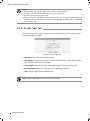
66666666 Ping
The ping function is to test the connectedness of the link between the switch and
destination. This page is shown as below:
Web Management
40
Gigabit Uplink Web Smart Switch
FFFFFFFFFFFFPing
¾¾ Destination IP Address: Indicates the IP Address of the test destination.
¾¾ Ping Count: Indicates the ping times in one submission.
¾¾ Data Size: Indicates the data field length of ping packet.
¾¾ Ping Interval: Indicates the time interval between two continuous pings.
666666 VLAN Setting
66666666 VLAN Mode
This page selects the VLAN Mode, and possible field values are:
FFFFFFFFFFFFVLAN Mode
¾¾ VLAN Disable: Do not set any VLAN in the switch, all ports of the switch can
communicate with each other.
¾¾ Port VLAN (Port-Based VLAN): Set the Port-Based VLAN mode.
¾¾ Tag VLAN (802.1Q Tag VLAN): Set the 802.1Q Tag VLAN mode.
¾¾ MTU VLAN: Set the MTU VLAN mode. This mode cannot be set if any Trunk has
been set.
41
Web Management
Gigabit Uplink Web Smart Switch
66666666 Port VLAN Setting
This page is displayed when the switch is in Port VLAN mode and it contains the
following fields:
FFFFFFFFFFFFPort VLAN Setting
¾¾ VLAN: The VLAN number. Select the number of the VLAN you want to configure
here.
¾¾ Port: The switch port number.
¾¾ Member: Selects the member of the VLAN here. If this field is checked, it indicates
the port belongs to the current VLAN.
¾¾ Description: Displays the user-defined port description.
¾¾ All VLAN: Displays all defined Port VLANs.
FFFFFFFFFFFFAll Port VLAN
¾¾ Select All: Select all ports to be the VLAN member.
¾¾ Clean Up: Clean up all members of the VLAN.
¾¾ Submit: Submit to buildup a VLAN with the selected members.
Note:
Any VLAN cannot be the subset or superset of other VLANs.
At least two port members should be included to add a VLAN group. (If the page is
submitted with 0 VLAN member, it indicates to delete the VLAN.)
If any Trunk has been set, the Trunk can be configured as a VLAN member, and the
member ports of the Trunk cannot be configured (see Port 1 and 2 in Figure 6-37 for
example).
For the first time the Port VLAN mode is set, a default VLAN, which is indexed as NO.
1 and contains all switch ports, will be built up.
The ports haven’t been assigned to any VLAN manually will be assigned to a hidden
VLAN automatically to make sure they can communicate with each other.
The number of Port VLAN can be set is the same as the switch port number.
■■
■■
■■
■■
■■
■■
Web Management
42
Gigabit Uplink Web Smart Switch
66666666 Tag VLAN Global Setting
This page is displayed when the switch is in Tag VLAN mode, the global setting of the
ports will affect all Tag VLANs. It contains the following fields:
FFFFFFFFFFFFTag VLAN Global Setting
¾¾ Port: The switch port number.
¾¾ PVID: While receiving an untagged frame from the port, the switch will assign a tag
to the frame, using the PVID of the port as its VID.
¾¾ Untag Frame: The solution to the untagged frame received. "Drop" will drop the
frame and "Pass" will transmit the frame in the VLAN with the VID the same as the
PVID of the port.
¾¾ All Ports: By operating on this field expediently, you can set the values of all ports
in the corresponding field.
¾¾ Notice: If any Trunk has been set, the Trunk can be configured, but member
ports of the Trunk are not able to be configured and in the fields it displays the
parameters of the Trunk they belong to. (see port1 and 2 in Figure 6-39 for
example).
43
Web Management
Gigabit Uplink Web Smart Switch
66666666 Tag VLAN Setting
This page is displayed when the switch is in Tag VLAN mode and it contains the
following fields. It configures each VLAN and is affected by the global setting of the
ports.
FFFFFFFFFFFF Tag VLAN Setting
¾¾ VLAN: The VLAN number. Select the number of the VLAN you want to configure
here.
¾¾ VLAN ID: Configure the VLAN ID.
¾¾ Port: The switch port number.
¾¾ Member: Select the member of the VLAN here. If this field is checked, it indicates
the port belongs to the current VLAN.
¾¾ Egress Frame: The solution to the egress frame. "Drop Tag" indicates drop the
tag header before sending the frame. "Add Tag" indicates add the tag header
before sending the frame. "Unmodify” indicates not to modify the tag header before
sending the frame.
¾¾ Description: Displays the user-defined port description.
¾¾ All Ports: By operating on this field expediently, you can set the values of all ports
in the corresponding field.
¾¾ All VLAN: Displays all defined Tag VLANs.
FFFFFFFFFFFFAll Tag VLAN
¾¾ Select All: Select all ports to be the VLAN member.
Web Management
44
Gigabit Uplink Web Smart Switch
¾¾ Clean Up: Clean up all members of the VLAN.
¾¾ Submit: Submit to buildup a VLAN with the selected members.
Note:
VID of the VLAN must be unique and within the range of 1 to 4094.
At least two port members should be included to add a VLAN group. (If the page is
submitted with 0 VLAN member, it indicates to delete the VLAN.)
If any Trunk has been set, the Trunk can be configured as a VLAN member and
member ports of the Trunk cannot be configured (see Port 1 and 2 in Figure 6-40 for
example).
If the port is connected to a device that doesn’t support IEEE802.1Q (e.g. HUB and
some network adapter), value of the Egress Frame field should be set to “Drop Tag”.
For the first time the Port VLAN mode is set, a default VLAN, which is indexed as NO.
1 and contains all switch ports, will be built up.
The ports haven’t been assigned to any VLAN manually cannot communicate with
each other or other VLAN. That’s different from the Port VLAN.
The number of Port VLAN that can be set depends on the switch type. See the
Appendix C for details.
■■
■■
■■
■■
■■
■■
■■
66666666 MTU VLAN Setting
This page, which is designed to configure the uplink port, is displayed when the switch
is in MTU VLAN mode.
FFFFFFFFFFFFMTU VLAN Setting
Note:
The uplink port will buildup several VLANs with each of the other ports. Each VLAN
contains two ports, the uplink port and one of the other ports in the switch, so the
uplink port can communicate with any other port but other ports can’t communicate
with each other.
First time the MTU VLAN mode is set, it set port 1 to be the uplink port by default.
■■
■■
666666 Port Trunking
This page contains the following fields:
45
Web Management
Gigabit Uplink Web Smart Switch
FFFFFFFFFFFFPort Trunking
¾¾ Trunk: The Trunk number.
¾¾ Member: Select the member of the Trunk here. Each group has 4 optional ports to
compose a Trunk.
¾¾ Storm Control: configure the storm control for the Trunk here. All member ports
of the Trunk share the same settings. Subfield of the Storm Control are the same as
that of the port storm control, see phase 6.3.2.4 for details.
¾¾ Select All: Select all Trunk members in the list.
¾¾ Clean Up: Clean up the Trunk member list.
Note:
Each Trunk should contains 2 to 4 ports (If a Trunk is submitted with 0 member port,
it indicates to delete the Trunk).
SFP and 1000Mbps port in TL-SL2210WEB/TL-SL2218WEB/TL-SL2428WEB/TLSL2452WEB, is not able to be the Trunk member.
Trunks cannot be set if the switch is in MTU VLAN mode.
■■
■■
■■
666666 Priority Setting
Priority setting contains four topics: priority mode, port-based priority, port default
priority and 802.1p priority.
Because dynamic menu is adopted, only the pages corresponding to current priority
mode are revealed. If the parameters of other priority modes are to be configured,
select the corresponding priority mode in “Priority Mode” page first.
66666666 Priority Mode
This page is shown below:
FFFFFFFFFFFF Priority Mode
Web Management
46
Gigabit Uplink Web Smart Switch
¾¾ Priority Mode: Contains “Disable”, “Port-Based” and “IEEE802.1p”.
¾¾ Priority Rule: Contains “Weighted” and “Fixed”. If the priority mode is set to be
“Disable”, the priority rule cannot be configured.
66666666 Port-Based Priority
This page is revealed when the “Port-Based” mode is configured. As shown below.
FFFFFFFFFFFFPort-Based priority
¾¾ Port: Indicates the switch port number.
¾¾ Priority Class: In port-based priority mode, the switch ports are classified into four
priority classes: lowest, lower, higher and highest. All the packets entering from the
port of the switch are forwarded in the correspondingpriority queue.
Further explanation: When priority rule is configured as "weighted", a 1,2,4,8
weighting is applied to forward these four classes of packets.
66666666 Port Default Priority
This page is revealed when the “IEEE802.1p” mode is configured. When a switch port
receives an untagged frame (a frame without priority tag), the port's default priority
tag will be inserted into the frame before any other process.
FFFFFFFFFFFF Port Default Priority
¾¾ Port: Indicates the switch port number.
¾¾ Default Priority Tag: Indicates 802.1p tag being inserted into untagged frames.
47
Web Management
Gigabit Uplink Web Smart Switch
66666666 802.1p Priority Class
This page is revealed when the “IEEE802.1p” mode is configured. As shown below:
FFFFFFFFFFFF802.1p Priority
¾¾ Priority Tag: The priority tag defined in IEEE802.1p.
¾¾ Corresponding Priority Class: Indicates the inner priority classes of switch. The
tagged frames are classified into four classes inside the switch: lowest, lower, higher
and highest. When the “Weighted” priority rule is configured, a 1,2,4,8 weighting is
applied to forward these four classes of packets.
Further explanation: In IEEE802.1p priority mode, when a switch port receives
an untagged frame (a frame without priority tag), the port's default priority tag will
be inserted into the frame before any other process.
666666 Port Mirroring
This page contains the following fields:
FFFFFFFFFFFF Port Mirroring
¾¾ Mirror Mode: Set the mirror mode to monitor the ingress traffic, egress traffic, or
both. You can also disable port mirroring.
¾¾ Mirror Port: Defines the port to monitor the traffic. Trunk member can't be defined
here.
¾¾ Mirrored Port: Indicates the port from which the packets are mirrored. Trunk
member can't be defined here. At most 4 ports can be mirrored simultaneously.
¾¾ Clean Up: Clean Up the Mirrored Port list.
Web Management
48
Gigabit Uplink Web Smart Switch
Note:
Trunk member port can be neither Mirror Port nor Mirrored Port.
The Mirror Port can’t be the Mirrored Port at the same time.
At most 4 Mirrored Ports can be set.
While setting the 100Mbps ports as Mirror Port, it’s not able to select SFP and
1000Mbps ports in the Mirrored Port list. It’s suggested to set the SFP or 1000Mbps
ports as Mirror Port.
■■
■■
■■
■■
666666 Virtual Cable Test
The virtual cable test feature enables you test the continuity of the cable circuit. It
contains the following fields:
FFFFFFFFFFFFVirtual Cable Test
¾¾ Test Port: Select the port you want to test.
¾¾ Link Status: Reports good status or issues such as cable opens, cable shorts or
any impedance mismatch in the cable.
¾¾ Link Length: Reports the range of the cable length if the link status is good.
¾¾ Fault Distance: Reports the distance to the open/short location.
¾¾ Test: Test the cable via the selected port.
Note: Cable connected to the SFP cannot be tested.
49
Web Management
Gigabit Uplink Web Smart Switch
Appendix A Troubleshooting
QQQQ Why does the Power LED work abnormally?
The Power LED should be lit up when the power system works normally. If the
Power LED worked abnormally, please take the following steps:
111 Make sure that the power cable is connected properly, and the power contact
is normal.
222 Make sure the voltage of the power supply meets the requirement of the input
voltage of the Switch.
QQQQ What could I do if I could not access the web-based configuration
page?
You are recommended to check the following items:
111 Check every port LED on the Switch and make sure the cable is installed
properly.
222 Try another port on the Switch and make sure the cable meets the requirement
and works normally.
333 Turn off the power. After a while, turn on the power again.
444 Make sure the IP address of your PC is set within the subnet of the Switch.
555 If you still cannot access the configuration page, please restore the Switch to
its factory defaults. Then the IP address should be set as 192.168.0.x ("x" is
any number from 2 to 254) and Subnet Mask as 255.255.255.0.
Troubleshooting
50
Gigabit Uplink Web Smart Switch
Appendix B Table of Factory Defaults
Table of Factory Defaults:
Function
Feature
System Information
System Setting
File Transfer
User
Port Parameter
Port Setting
Port Statistic
Storm Control
Port Description
Switch IP Address
Static MAC Address
Default Setting
System Name
Null
System Location
Null
Contact Information
Null
Transfer Type
System Upgrading
File Name
SysSL2210WEB.bin
User Name
supervisor
Password
supervisor
Port Status
Enable
Port Security
Disable
Flow Control
Disable
Duplex Mode
Auto
All
0
Broadcast Control
Disable
Multicast Control
Disable
UL Control
Disable
Limit Rate
64K
Null
DHCP client
Disable
IP Address
192.168.0.1
Netmask
255.255.255.0
Default Gateway
Null
Null
Filtering MAC Address Null
Network Setting
Dynamic Binding
Table of Factory Defaults
Disable
Number of MAC
Address to Bind
5
Bound MAC Address
Null
Aging Time
Aging Time
300
Ping
51
Binding
Destination IP Address
192.168.0.1
Ping Count
4
Data Size
64
Ping Interval
1000
Gigabit Uplink Web Smart Switch
Function
VLAN Setting
Port Trunking
Feature
Default Setting
VLAN Mode
Disable
Port VLAN Setting
All ports belong to VLAN 1
Tag VLAN
Global Setting
PVID
1
Untag Frame
Pass
Tag VLAN Setting
All ports belong to VLAN 1; the VID is 1 and
“Egress Frame” is "Drop Tag"
MTU VLAN Setting
Uplink port
1
Priority Mode
Disable
No configured Trunk
Priority Mode
Priority Setting
Priority Rule
Weighted
Port-Based Priority
Priority Class
Lowest
Port Default Priority
Port Default Priority Tag
0
Priority Tag 0,1
Lowest
Priority Tag 2,3
Lower
802.1P Priority
Port Mirroring
Port Mirroring
Priority Tag 4,5
Higher
Priority Tag 6,7
Highest
Mirror Mode
Disable
Mirror Port
1
Mirrored Port
Null
Table of Factory Defaults
52
Gigabit Uplink Web Smart Switch
Appendix C Table of Function Differences of Switch Family
Table of Function Differences of Switch Family:
Function
TL-SL2210WEB
TL-SL2218WEB
TL-SL2428WEB
TL-SL2452WEB
Port
10
18
28
52
Giga Port
2
2
4
4
SFP Port
1
1
2
2
Trunk
2
4
6
8
Port VLAN
10
18
28
52
Tag VLAN
64
64
128
256
Static MAC
64
128
128
128
Filtering MAC
64
128
128
128
128
256
384
544
9W MAX
13W MAX
20W MAX
35W MAX
Dynamic
Binding MAC
Power
Consumption
53
Models
Table of Function Differences of Switch Family
Gigabit Uplink Web Smart Switch
Appendix D Hardware Specifications
Item
Content
IEEE 802.3 10Base-T
IEEE802.3u 100Base-TX
Standards and Protocol
IEEE802.3ab 1000Base-T
IEEE802.3z 1000Base-X
IEEE802.3x Flow Control
10Base-T: UTP/STP of Cat. 3 or above
Transmission Medium
100Base-TX: UTP/STP of Cat. 5 or above
1000Base-X: MMF or SMF SFP Module (Optional1
Safety & Emissions
FCC, CE
Transfer Method
Store-and-Forward
MAC Address Learning
Automatically learning, automatically aging
Frame Forward Rate
10Base-T: 14881pps/Port
100Base-Tx: 148810pps/Port
LEDs
Power, System, Link/Act, 100Mbps, 1000Mbps
Operating Temperature
0℃~40℃
Storage Temperature
-40℃~70℃
Operating Humidity
10% ~ 90% RH Non-condensing
Storage Humidity
5% ~ 90% RH Non-condensing
Hardware Specifications
54
Gigabit Uplink Web Smart Switch
Appendix E Technical Support
■■
■■
For more help, please go to: www.tp-link.com/support/faq.asp
To download the latest Firmware, Driver, Utility and User Guide, please go to:
www.tp-link.com/support/download.asp
■■
55
For all other technical support, please contact us by using the following details:
Global
Tel: +86 755 26504400
E-mail: [email protected]
Service time: 24hrs, 7 days a week
Singapore
Tel: +65 62840493
E-mail: [email protected]
Service time: 24hrs, 7 days a week
UK
Tel: +44 (01 845 147 0017
E-mail: [email protected]
Service time: 24hrs, 7 days a week
USA/Canada
Toll Free: +1 866 225 8139
E-mail: [email protected]
Service time: 24hrs, 7 days a week
Australia & New Zealand
Tel: AU 1300 87 5465 NZ 0800 87 5465
E-mail: [email protected]
Service time: 24hrs, 7 days a week
Malaysia
Tel: 1300 88 875465 (1300 88TPLINK1
Email: [email protected]
Service time: 24hrs, 7 days a week
Turkey
Tel: 444 19 25 (Turkish Service1
E-mail: [email protected]
Service time: 9:00 AM to 6:00 PM, 7 days a week
Italy
Tel: +39 02 66987799
E-mail: [email protected]
Service time: 9:00 AM to 6:00 PM, Monday to Friday
Indonesia
Tel: (+62 1 021 6259 135
E-mail: [email protected]
Service time: Monday to Friday
9:00-12:00 ; 13:00-18:00
*Except public holidays
Germany/Austria
Tel: +49 1805 875465 (German Service1/+49 1805 TPLINK
E-mail: [email protected]
Fee: 0.14 EUR/min from the German fixed phone network and up to 0.42
EUR/min from mobile phone
Service time: Monday to Friday 9:00 AM to 6:00 PM
GMT+ 1 or GMT+ 2 (Daylight Saving Time in Germany1
*Except bank holidays in Hesse
Switzerland
Tel: +41 (01848 800998 (German Service1
E-mail: [email protected]
Fee: 4-8 Rp/min, depending on rate of different time
Service time: Monday to Friday 9:00 AM to 6:00 PM,
GMT+ 1 or GMT+ 2 (Daylight Saving Time1
Technical Support
Website: http://www.tp-link.com
E-mail: [email protected]
7106503690
Rev: 2.0.0