Transcript
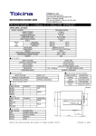
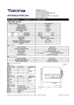
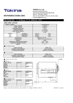
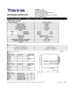
TOKINA Co.,Ltd.
Security Products Division
120-4 NOZUTA-MACHI,MACHIDA-SHI,
TOKYO, 195-0063 JAPAN
TEL:+81-42-734-8912 FAX:+81-42-736-0143
E-mail:[email protected]
APT-641 Speed dome controller
SPECIFICATION
Video Input
8 CAMERA INPUT and EACH THROUGHOUT
Video Output
MAIN OUTPUT/SPOT OUTPUT
LCD Display
16 x 2 Display
Alarm Input
up to 8 Inputs
Preset
64 Preset Points
OSD Display
MENU and CAMERA ID (up to 10 characters)
AUTO/AUTO PAN/SWITCHER
Function Key
Focus
NEAR/FAR
Joystick
PAN/TILT/ZOOM Simultaneous Control
VSD-640
RS-485 Communication Interface
External Units/PC
RS-232 Communication Interface
Power Source
DC 12V (500mA)
Power Consumption
6W
Weight
2kg
Dimensions
345(W)x67(H)x206(D)mm
* Specifications and design subject to change without notice for improvements.
Front Panel Front Panel Controls
Rear Panel Rear Panel Controls
1. LCD DISPLAY
This presents the setting state.
2. KEYPAD BUTTON
This button is used to control PRESET and CAMERA.
3. CLEAR
This button is a STOP function button.
4. ENT
This button is a ENTER button that selects PRESET and CAMERA.
Besides this button is used the button selects cameras of external unit.
5. PRESET
This button is a PRESET button that selects preset positions.
6. CAM
This button is a CAMERA button that selects cameras and
applys switcher function.
7. REW
This button is a REWIND button for AUTO/AUTO PAN.
8. FF
This button is a FORWARD button for AUTO/AUTO PAN.
9. AUTO
This button is AUTO Sequence and SWITCHER button.
10. AUTO PAN
This button is AUTO PAN button.
11. FAR
This button is a Far button for manual focus.
12. NEAR
1. VIDEO INPUT JACKS
This jack is used as video input jacks up to eight video inputs.
2. EACH THROUGH OUTPUT JACKS
This jack is a Throughout jack of each video input.
3. VIDEO OUTPUT JACKS
This jack is used as the output of video input.
Outputs consists of two outputs, AUTO and SPOT output.
4. ALARM INPUT TERMINALS
This terminal is used as ALARM inputs.
5. RS-485 TERMINAL
This terminal is used as RS-485 Communication.
6. PC
This D-SUB Jack is used to control this unit by PC.(OPTION)
7. EXTERNAL UNITS
This D-SUB Jack is used to connect the external unit.
8. DC POWER JACK
This jack is a DC Power jack, DC 12V.
This button is a NEAR button for manual focus.
13. MENU
This button is a MENU button for OSD Display.
Be sure to push the button over 3 sec to operate MENU.
14. CAM SW/IR
This button is CAM SW button for VRX-2201 and IR button.
15. LIGHT/WDR
This button is LIGHT button for VRX-2201 and WDR button.
16. AUX
This button is an AUX button for VRX-2201.
17. LOCK
This button is a LOCK button for preventing the preset setting from mishandling.
Be sure to push the button over 3 sec to operate LOCK.
18. JOYSTICK
This is a Joystick that manually controls PAN/TILT/ZOOM.
19. POWER SWITCH
This switch is a POWER ON/OFF button.