1
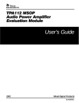
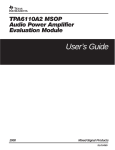
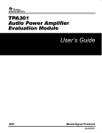
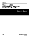
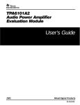
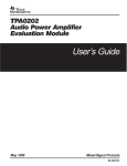
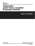
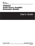
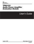
TPA102 MSOP Audio Power Amplifier Evaluation Module User’s Guide May 2001 Mixed-Signal Products SLOU022A IMPORTANT NOTICE Texas Instruments and its subsidiaries (TI) reserve the right to make changes to their products or to discontinue any product or service without notice, and advise customers to obtain the latest version of relevant information to verify, before placing orders, that information being relied on is current and complete. All products are sold subject to the terms and conditions of sale supplied at the time of order acknowledgment, including those pertaining to warranty, patent infringement, and limitation of liability. TI warrants performance of its products to the specifications applicable at the time of sale in accordance with TI’s standard warranty. Testing and other quality control techniques are utilized to the extent TI deems necessary to support this warranty. Specific testing of all parameters of each device is not necessarily performed, except those mandated by government requirements. Customers are responsible for their applications using TI components. In order to minimize risks associated with the customer’s applications, adequate design and operating safeguards must be provided by the customer to minimize inherent or procedural hazards. TI assumes no liability for applications assistance or customer product design. TI does not warrant or represent that any license, either express or implied, is granted under any patent right, copyright, mask work right, or other intellectual property right of TI covering or relating to any combination, machine, or process in which such products or services might be or are used. TI’s publication of information regarding any third party’s products or services does not constitute TI’s approval, license, warranty or endorsement thereof. Reproduction of information in TI data books or data sheets is permissible only if reproduction is without alteration and is accompanied by all associated warranties, conditions, limitations and notices. Representation or reproduction of this information with alteration voids all warranties provided for an associated TI product or service, is an unfair and deceptive business practice, and TI is not responsible nor liable for any such use. Resale of TI’s products or services with statements different from or beyond the parameters stated by TI for that product or service voids all express and any implied warranties for the associated TI product or service, is an unfair and deceptive business practice, and TI is not responsible nor liable for any such use. Also see: Standard Terms and Conditions of Sale for Semiconductor Products. www.ti.com/sc/docs/stdterms.htm Mailing Address: Texas Instruments Post Office Box 655303 Dallas, Texas 75265 Copyright 2001, Texas Instruments Incorporated Preface How to Use This Manual This document contains the following chapters: - Chapter 1—Introduction Chapter 2—Quick Start Chapter 3—Details Related Documentation From Texas Instruments - TI Plug-N-Play Audio Amplifier Evaluation Platform (literature number SLOU011) provides detailed information on the evaluation platform and its use with TI audio evaluation modules. TPA102 150-mW Stereo Audio Power Amplifier (literature number SLOS213) This is the data sheet for the TPA102 audio amplifier integrated circuit. This book may contain cautions and warnings. This is an example of a caution statement. A caution statement describes a situation that could potentially damage your software or equipment. This is an example of a warning statement. A warning statement describes a situation that could potentially cause harm to you. The information in a caution or a warning is provided for your protection. Please read each caution and warning carefully. Read This First iii Running Title—Attribute Reference FCC Warning This equipment is intended for use in a laboratory test environment only. It generates, uses, and can radiate radio frequency energy and has not been tested for compliance with the limits of computing devices pursuant to subpart J of part 15 of FCC rules, which are designed to provide reasonable protection against radio frequency interference. Operation of this equipment in other environments may cause interference with radio communications, in which case the user at his own expense will be required to take whatever measures may be required to correct this interference. iv Running Title—Attribute Reference Contents 1 Introduction . . . . . . . . . . . . . . . . . . . . . . . . . . . . . . . . . . . . . . . . . . . . . . . . . . . . . . . . . . . . . . . . . . . . . 1.1 Features . . . . . . . . . . . . . . . . . . . . . . . . . . . . . . . . . . . . . . . . . . . . . . . . . . . . . . . . . . . . . . . . . . 1.2 Description . . . . . . . . . . . . . . . . . . . . . . . . . . . . . . . . . . . . . . . . . . . . . . . . . . . . . . . . . . . . . . . . 1.3 TPA102 MSOP EVM Specifications . . . . . . . . . . . . . . . . . . . . . . . . . . . . . . . . . . . . . . . . . . . 1-1 1-2 1-3 1-3 2 Quick Start . . . . . . . . . . . . . . . . . . . . . . . . . . . . . . . . . . . . . . . . . . . . . . . . . . . . . . . . . . . . . . . . . . . . . . 2.1 Precautions . . . . . . . . . . . . . . . . . . . . . . . . . . . . . . . . . . . . . . . . . . . . . . . . . . . . . . . . . . . . . . . . 2.2 Quick Start List for Platform . . . . . . . . . . . . . . . . . . . . . . . . . . . . . . . . . . . . . . . . . . . . . . . . . . 2.3 Quick Start List for Stand-Alone . . . . . . . . . . . . . . . . . . . . . . . . . . . . . . . . . . . . . . . . . . . . . . 2-1 2-2 2-3 2-4 3 Details . . . . . . . . . . . . . . . . . . . . . . . . . . . . . . . . . . . . . . . . . . . . . . . . . . . . . . . . . . . . . . . . . . . . . . . . . . 3-1 3.1 Precautions . . . . . . . . . . . . . . . . . . . . . . . . . . . . . . . . . . . . . . . . . . . . . . . . . . . . . . . . . . . . . . . . 3-2 3.2 The TPA102 MSOP Audio Amplifier Evaluation Module . . . . . . . . . . . . . . . . . . . . . . . . . . 3-3 3.2.1 TPA102 Audio Amplifier IC . . . . . . . . . . . . . . . . . . . . . . . . . . . . . . . . . . . . . . . . . . . . 3-4 3.2.2 Module Gain . . . . . . . . . . . . . . . . . . . . . . . . . . . . . . . . . . . . . . . . . . . . . . . . . . . . . . . . 3-5 3.2.3 Shutdown . . . . . . . . . . . . . . . . . . . . . . . . . . . . . . . . . . . . . . . . . . . . . . . . . . . . . . . . . . 3-5 3.3 Using the TPA102 MSOP EVM With the Plug-N-Play Evaluation Platform . . . . . . . . . . 3-6 3.3.1 Installing and Removing EVM Boards . . . . . . . . . . . . . . . . . . . . . . . . . . . . . . . . . . 3-6 3.3.2 Signal Routing . . . . . . . . . . . . . . . . . . . . . . . . . . . . . . . . . . . . . . . . . . . . . . . . . . . . . . 3-7 3.3.3 Shutdown . . . . . . . . . . . . . . . . . . . . . . . . . . . . . . . . . . . . . . . . . . . . . . . . . . . . . . . . . . 3-8 3.3.4 Power Requirements . . . . . . . . . . . . . . . . . . . . . . . . . . . . . . . . . . . . . . . . . . . . . . . . . 3-9 3.3.5 Inputs and Outputs . . . . . . . . . . . . . . . . . . . . . . . . . . . . . . . . . . . . . . . . . . . . . . . . . 3-10 3.4 Using the TPA102 MSOP EVM Stand-Alone . . . . . . . . . . . . . . . . . . . . . . . . . . . . . . . . . . 3-11 3.4.1 TPA102 MSOP EVM Connected as a Stereo Headphone Amplifier . . . . . . . 3-11 3.5 TPA102 MSOP Audio Power Amplifier Evaluation Module Parts List . . . . . . . . . . . . . . 3-12 Chapter Title—Attribute Reference v Running Title—Attribute Reference Figures 1–1 2–1 2–2 3–1 3–2 3–3 3–4 3–5 3–6 3–7 3–8 The TI TPA102 MSOP Audio Amplifier Evaluation Module . . . . . . . . . . . . . . . . . . . . . . . . . . 1-4 Quick Start Platform Map . . . . . . . . . . . . . . . . . . . . . . . . . . . . . . . . . . . . . . . . . . . . . . . . . . . . . . 2-2 Quick Start Module Map . . . . . . . . . . . . . . . . . . . . . . . . . . . . . . . . . . . . . . . . . . . . . . . . . . . . . . . 2-4 The TI Plug-N-Play Audio Amplifier Evaluation Platform . . . . . . . . . . . . . . . . . . . . . . . . . . . . 3-2 TPA102 MSOP EVM . . . . . . . . . . . . . . . . . . . . . . . . . . . . . . . . . . . . . . . . . . . . . . . . . . . . . . . . . . 3-3 TPA102 MSOP EVM Schematic Diagram . . . . . . . . . . . . . . . . . . . . . . . . . . . . . . . . . . . . . . . . 3-3 TPA102 Audio Amplifier IC . . . . . . . . . . . . . . . . . . . . . . . . . . . . . . . . . . . . . . . . . . . . . . . . . . . . . 3-4 Platform Signal Routing and Outputs . . . . . . . . . . . . . . . . . . . . . . . . . . . . . . . . . . . . . . . . . . . . 3-7 Mute Polarity Control . . . . . . . . . . . . . . . . . . . . . . . . . . . . . . . . . . . . . . . . . . . . . . . . . . . . . . . . . . 3-8 Typical Headphone Plug . . . . . . . . . . . . . . . . . . . . . . . . . . . . . . . . . . . . . . . . . . . . . . . . . . . . . . 3-10 TPA102 MSOP EVM Connected as a Stereo Headphone Amplifier . . . . . . . . . . . . . . . . . 3-11 Tables 2–1 2–2 3–1 vi Typical TI Plug-N-Play Platform Jumper and Switch Settings for the TPA102 MSOP EVM . . . . . . . . . . . . . . . . . . . . . . . . . . . . . . . . . . . . . . . . . . . . . . . . . . . . . . . . . 2-1 Platform Jumper and Switch Settings for the TPA102 MSOP EVM . . . . . . . . . . . . . . . . . . . 2-3 TPA102 MSOP EVM Parts List . . . . . . . . . . . . . . . . . . . . . . . . . . . . . . . . . . . . . . . . . . . . . . . . 3-12 Chapter 1 Introduction This chapter provides an overview of the Texas Instruments (TI) TPA102 MSOP audio amplifier evaluation module (SLOP125). It includes a list of EVM features, a brief illustrated description of the module, and a list of EVM specifications. Topic Page 1.1 Features . . . . . . . . . . . . . . . . . . . . . . . . . . . . . . . . . . . . . . . . . . . . . . . 1–2 1.2 Description . . . . . . . . . . . . . . . . . . . . . . . . . . . . . . . . . . . . . . . . . . . . . . . . . . . 1–3 1.3 TPA102 MSOP EVM Specifications . . . . . . . . . . . . . . . . . . . . . . . . . . . . . 1–3 Introduction 1-1 Features 1.1 Features The TI TPA102 MSOP audio amplifier evaluation module and the TI plug-n-play audio amplifier evaluation platform include the following features: - - TPA102 MSOP stereo audio power amplifier evaluation module J J J J J J J - 1-2 150 mW output power into 8 Ω at 5 V 2.5-V to 5.5-V operation Very low distortion — THD+N is less than 0.01% at 1 kHz and less than 0.03% from 20 Hz to 20 kHz into 10-kΩ loads, less than 0.02% at 1 kHz and less than 0.4% from 20 Hz to 20 kHz into 32-Ω loads, and less than 0.05% at 1 kHz and less than 0.8% from 20 Hz to 20 kHz into 8-Ω loads Extremely low current consumption in shutdown mode Internal thermal and short-circuit protection Internal pop reduction circuitry Quick and easy configuration with the TI plug-n-play audio amplifier evaluation platform J - Dual channel, single-ended operation J J J J Evaluation module is designed to simply plug into the platform, automatically making all signal, control, and power connections Platform provides flexible power options Jumpers on the platform select power and module control options Switches on the platform route signals Platform provides quick and easy audio input and output connections Platform power options J J J J J Onboard 9-V battery External 5-V – 15-V (VCC) supply inputs External regulated VDD supply input Socket for onboard 5-V VDD voltage regulator EVM Onboard overvoltage and reverse polarity power protection Platform audio input and output connections J J J J J Left and right RCA phono jack inputs Miniature stereo phone jack input Left and right RCA phono jack outputs Left and right compression speaker terminal outputs Miniature stereo headphone jack output Introduction Description 1.2 Description The TPA102 MSOP audio power amplifier evaluation module is a complete, low-power stereo audio power amplifier for high-fidelity line-level output, headphone, and small speaker applications. It consists of the TI TPA102 150-mW stereo audio power amplifier IC in a very small MSOP package, along with a small number of other parts mounted on a circuit board that is approximately one and a quarter inches square (Figure 1–1). Figure 1–1. The TI TPA102 MSOP Audio Amplifier Evaluation Module VDD GND Shutdown S1 C4 R2 C3 IN1 GND C7 R1 R3 C1 U1† C5 C2 Vo1 GND R4 R5 TEXAS INSTRUMENTS IN2 GND SLOP125 TPA102 MSOP EVM GND Vo2 † Due to the very small size of the MSOP IC package, the standard part number TPA102 is replaced with the code TIAAC Single in-line header pins are mounted to the underside of the module circuit board to allow the EVM to be plugged into the TI plug-n-play audio amplifier evaluation platform, or to be wired directly into existing circuits and equipment when used stand-alone. The platform has room for a single TPA102 evaluation module and is a convenient vehicle for demonstrating TI’s audio power amplifier and related evaluation modules. The EVMs simply plug into the platform, which automatically provides power to the modules, interconnects them correctly, and connects them to a versatile array of standard audio input and output jacks and connectors. Easy-to-use configuration controls allow the platform and EVMs to quickly model many possible end-equipment configurations. There is nothing to build, nothing to solder, and nothing but the speakers included with the platform to hook up. 1.3 TPA102 MSOP EVM Specifications Supply voltage range, VDD . . . . . . . . . . . . . . . . . . . . . . . . . . . . . . . . . . . . . . . . . . . . . . 2.5 V to 5.5 V Supply current, IDD . . . . . . . . . . . . . . . . . . . . . . . . . . . . . . . . . . . . . . . . . . . . . . . . . . . . . 160 mA, max Continuous output power, PO: 8 Ω, VDD = 5 V . . . . . . . . . . . . . . . . . . . . . . . . . . . . . . . . . . . 150 mW Audio input voltage, VI . . . . . . . . . . . . . . . . . . . . . . . . . . . . . . . . . . . . . . . . . . . . VDD + 0.3 Vpp, max Minimum load impedance, RL . . . . . . . . . . . . . . . . . . . . . . . . . . . . . . . . . . . . . . . . . . . . . . . . . . . . 8 Ω Introduction 1-3 1-4 Introduction Chapter 2 Quick Start The steps in this chapter can be followed to quickly prepare the TPA102 MSOP audio amplifier EVM for use. Using the TPA102 MSOP EVM with the TI plug-n-play audio amplifier evaluation platform is a quick and easy way to connect power, signal and control inputs, and signal outputs to the EVM using standard connectors. However, the audio amplifier evaluation module can be used stand-alone by making connections directly to the module pins, and can be wired directly into existing circuits or equipment. The platform switch and jumper settings shown in Table 2–1 are typical for the TPA102 MSOP EVM and will cause the TPA102 IC to shutdown/mute when a plug is removed from platform headphone jack J10. Table 2–1. Typical TI Plug-N-Play Platform Jumper and Switch Settings for the TPA102 MSOP EVM EVM JP6 JP7 JP8 S2 S3 TPA102 X Lo X Note 2 U5 Notes: 1) X = Don’t care 2) Set S2 to ON when signal conditioning board is installed in U1; set S2 to OFF when no signal conditioning board is installed. Topic Page 2.1 Precautions . . . . . . . . . . . . . . . . . . . . . . . . . . . . . . . . . . . . . . . . . . . . . . . . . . 2–2 2.2 Quick Start List for Platform . . . . . . . . . . . . . . . . . . . . . . . . . . . . . . . . . . . 2–3 2.3 Quick Start List for Stand-Alone . . . . . . . . . . . . . . . . . . . . . . . . . . . . . . . . 2–4 Quick Start 2-1 Precautions 2.1 Precautions Power Supply Input Polarity and Maximum Voltage Always ensure that the polarity and voltage of the external power connected to VCC power input connector J1, J2, and/or VDD power input connector J6 are correct. Overvoltage or reverse-polarity power applied to these terminals can open onboard soldered-in fuses and cause other damage to the platform, installed evaluation modules, and/or the power source. Inserting or Removing EVM Boards Do not insert or remove EVM boards with power applied—damage to the EVM board, the platform, or both may result. Figure 2–1. Quick Start Platform Map 6b ICC + Right – Out U2 JP6 JP7 HP(U5) U2-U4 U5 U5 + Stereo Headphone Output J10 5 + S3 HP Source TP1 GND R3 Left J9 Out Spk(U2-U4) C3 C2 JP8 Mode Mute Polarity Lo Hi R4 2 Speaker Output + Left – Out U4 On Conditioning TEXAS INSTRUMENTS 1997 3 Out LED2 VDD U3 Off S2 U1 J5 Left In Plug-N-Play Audio Amplifier Evaluation Platform SLOP097 Rev. C.1 DC Power In/Out J7 Right J8 JP5 IDD LED1 VCC J4 Stereo In ****CAUTION**** Do not insert or remove EVM boards with power applied + J6 D1 D2 D3 J3 Right In Audio Input 2-2 R2 Audio Power Amps Signal Conditioning 8 VDD In/Out B1 D4 J2 AC/DC In R1 6a F2 6b Power Input VR2 S1 U6 POWER SUPPLY JP4 Pwr VR1 On Off JP3 Batt JP2 AC/DC J1 VCC In + JP1 (J2) VCC(J1) DC SOURCE F1 C1+ 6b 6b 1 10 HP Out 9 R5 4 Quick Start Quick Start List for Platform 2.2 Quick Start List for Platform - Follow these steps when using the TPA102 MSOP EVM with the TI Plug-N-Play audio amplifier evaluation platform (see the platform user’s guide, SLOU011, for additional details). Numbered callouts for selected steps are shown in Figure 2–1 and details appear in Chapter 3. Platform preparations 1) Ensure that all external power sources are set to OFF and that the platform power switch S1 is set to OFF. 2) Install a TPA102 MSOP module in platform socket U5, taking care to align the module pins correctly. 3) Use switch S2 to select or bypass the signal conditioning EVM (U1) 4) Set control signal polarity jumper JP7 to Lo. 5) Set Hp source switch S3 to U5 to route the output signal to the headphone Jack (J10). Table 2–2. Platform Jumper and Switch Settings for the TPA102 MSOP EVM EVM JP6 JP7 JP8 S2 S3 TPA102 X Lo X Note 2 U5 Notes: - 1) X = Don’t care 2) Set S2 to ON when signal conditioning board is installed in U1; set S2 to OFF when no signal conditioning board is installed. Power supply 6) Select and connect the power supply: a) Connect an external regulated power supply set to a voltage between 2.5 V and 5.5 V to platform VDD power input connector J6, taking care to observe marked polarity, or - b) Install a 3-V to 5-V voltage regulator EVM (SLVP097 or equiv.) in platform socket U6. Install a 9-V battery in B1 or connect a 7 V–12 V power source to a platform VCC power input J1 or J2 and jumper the appropriate power input (see platform user’s guide). Inputs and outputs 7) Ensure that signal source level is set to minimum. 8) Connect the audio source to left and right RCA phono jacks J3 and J5 or stereo miniature phone jack J4. - 9) Connect 32-Ω headphones to headphone jack J10. Power-up 10) Verify correct voltage and input polarity and set the external power supply to ON. If VCC and an on-board regulator EVM are used to provide VDD, set platform power switch S1 to ON. Platform LED2 should light indicating the presence of VDD, and the evaluation modules installed on the platform should begin operation. 11) Adjust the signal source level as needed. Quick Start 2-3 Quick Start List for Stand-Alone 2.3 Quick Start List for Stand-Alone Follow these steps to use the TPA102 MSOP EVM stand-alone or when connecting it into existing circuits or equipment. Connections to the TPA102 MSOP module header pins can be made via individual sockets, wire-wrapping, or soldering to the pins, either on the top or the bottom of the module circuit board. Numbered callouts for selected steps are shown in Figure 2–2 and details appear in Chapter 3. Figure 2–2. Quick Start Module Map 2 VDD GND Shutdown S1 5 4 C4 R2 C3 IN1 GND C7 R1 R3 C1 U1† C5 C2 Vo1 GND 6 GND Vo2 6 R4 R5 TEXAS INSTRUMENTS 4 - IN2 GND SLOP125 TPA102 MSOP EVM † Due to the very small size of the MSOP IC package, the standard part number TPA102 is replaced with the code TIAAC Power supply 1) Ensure that all external power sources are set to OFF. - 2) Connect an external regulated power supply set to 5 V to the module VDD and GND pins taking care to observe marked polarity. Inputs and outputs 3) Ensure that the signal source level is set to minimum. 4) Connect the audio source to the module IN1, IN2, and GND pins taking care to observe marked polarity. 5) Connect the Shutdown pin to VDD through a normally open switch. 6) Connect 32-Ω headphones to the module VO1, VO2 pins through 33 µF to 1000 µF output-coupling capacitors (figure 3 – 8) and return to the GND pin, or - 7) For line output, connections to the VO1 and VO2 pins must be made through 33 µF to 1000 µF output-coupling capacitors and returned to GND. Power-up 8) Verify correct voltage and input polarity and set the external power supply to ON. The EVM should begin operation. 9) Adjust the signal source level as needed. 2-4 Quick Start Chapter 3 Details This chapter provides details on the TPA102 IC, the evaluation module, the steps in the Quick-Start List, additional application information, and a parts list for the TPA102 MSOP evaluation module. Topic Page 3.1 Precautions . . . . . . . . . . . . . . . . . . . . . . . . . . . . . . . . . . . . . . . . . . . . . . . . . . 3–2 3.2 The TPA102 MSOP Audio Power Amplifier Evaluation Module . . . . 3–3 3.3 Using The TPA102 MSOP EVM With the Plug-N-Play Evaluation Platform . . . . . . . . . . . . . . . . . . . . . . . . . . . . . . . . . . . . . . . 3–6 3.4 Using the TPA102 MSOP EVM Stand-Alone . . . . . . . . . . . . . . . . . . . . . 3–11 3.5 TPA102 MSOP Audio Power Amplifier EVM Parts List . . . . . . . . . . 3–12 Details 3-1 Precautions 3.1 Precautions Power Supply Input Polarity and Maximum Voltage Always ensure that the polarity and voltage of the external power connected to VCC power input connector J1, J2, and/or VDD power input connector J6 are correct. Overvoltage or reverse-polarity power applied to these terminals can open onboard soldered-in fuses and cause other damage to the platform, installed evaluation modules, and/or the power source. Inserting or Removing EVM Boards Do not insert or remove EVM boards with power applied—damage to the EVM board, the platform, or both may result. Figure 3–1. The TI Plug-N-Play Audio Amplifier Evaluation Platform On Off C1+ ICC VR2 JP4 F2 + J6 VDD In/Out + Right – Out U3 Off S2 J4 Stereo In U2 U1 Speaker Output + On Conditioning Left Out J5 Left In – JP6 U4 Mode Mute Stereo Headphone Output HP Out J10 + R4 Left Out + S3 HP Source GND R3 J9 Lo Hi Spk(U2-U4) C3 C2 JP8 U5 U5 JP7 HP(U5) U2-U4 Polarity TP1 TEXAS INSTRUMENTS 1997 Plug-N-Play Audio Amplifier Evaluation Platform SLOP097 Rev. C.1 DC Power In/Out J8 J7 Right Out LED2 VDD Audio Power Amps ****CAUTION**** Do not insert or remove EVM boards with power applied 3-2 U6 JP5 IDD LED1 VCC J3 Right In R2 R1 Signal Conditioning Audio Input POWER B1 D1 D2 D3 D4 J2 AC/DC In SUPPLY S1 Pwr VR1 J1 JP3 Batt JP2 AC/DC (J2) JP1 VCC(J1) DC SOURCE VCC In + Power Input F1 R5 Details The TPA102 MSOP Audio Power Amplifier Evaluation Module 3.2 The TPA102 MSOP Audio Power Amplifier Evaluation Module The TPA102 MSOP audio power amplifier evaluation module is powered by a TPA102 150-mW stereo audio amplifier IC. It includes a shutdown control signal input with onboard switch and can drive either line-level outputs, 32-Ω headphones, or 8-Ω speakers. The evaluation module can be used with the TI plug-n-play audio amplifier evaluation platform (Figure 3 –1) or wired directly into circuits or equipment. The module has single in-line header connector pins mounted to the under side of the board. These pins allow the module to be plugged into the TI platform, which automatically makes all the signal input and output, power, and control connections to the module. The module connection pins are on 0.1-inch centers to allow easy use with standard perf board and plug board-based prototyping systems. Or, the EVM can be wired directly into existing circuits and equipment when used stand-alone. The module appears in Figure 3–2 and its schematic is shown in Figure 3 – 3. Figure 3–2. TPA102 MSOP EVM VDD GND Shutdown S1 C4 R2 C3 IN1 GND C7 R1 R3 C1 U1† C5 C2 Vo1 GND R4 R5 TEXAS INSTRUMENTS IN2 GND Vo2 SLOP125 TPA102 MSOP EVM GND † Due to the very small size of the MSOP IC package, the standard part number TPA102 is replaced with the code TIAAC Figure 3–3. TPA102 MSOP EVM Schematic Diagram Audio Input 1 R2 20 kΩ C3 1 µF 1 8 Bypass IN 1 C1 1 µF S1 2 VDD Vo1 GND NO Shutdown (VDD to Shutdown) 3 7 R3 80 kΩ Vo1 TPA102 MSOP Shutdown VDD 6 C5 1 µF C4 10 µF + R1 20 kΩ C2 1 µF R5 20 kΩ VDD 2.5 to 5.5 V GND 4 IN 2 Vo2 5 Vo2 Audio Input 2 R4, 80 kΩ Details 3-3 The TPA102 MSOP Audio Power Amplifier Evaluation Module 3.2.1 TPA102 Audio Amplifier IC The TPA102 audio amplifier IC is a CMOS device intended primarily for high-performance line-level output, headphone driver, and small speaker applications. It is supplied in a very small surface-mount MSOP package designed to operate from low supply voltages (between approximately 2.5 V and 5.5 V) and deliver up to approximately 150 mW into 8-Ω speakers with low distortion. As a line-level driver, distortion levels (THD+N) are below 0.03% into 10-kΩ loads across the audio band (20 Hz to 20 kHz). As a headphone driver, distortion levels are below 0.4% into 32-Ω loads across the audio band. And as a speaker driver, distortion levels are below 0.8% into 8-Ω loads across the audio band. Typical applications include portable computers, desktop computers, personal audio, toys, games, and similar audio applications. The IC includes two separate internal amplifiers, depop circuitry, and a common shutdown control (Figure 3– 4). The load for each channel is connected between the VO pin and GND through a coupling capacitor. For more information, see the TPA102 amplifier IC data sheet, TI literature number SLOS213. Figure 3–4. TPA102 Amplifier IC 6 VDD RF Stereo Audio Input RI CS 8 IN1 R 1 Bypass CI – CC VO1 7 + CB 2 From System Control 3 Shutdown RL Bias Control RL Stereo RI 4 IN2 L CI – VO2 5 CC + RF 3-4 Details The TPA102 MSOP Audio Power Amplifier Evaluation Module 3.2.2 Module Gain The TPA102 MSOP evaluation module has a set gain of 4 (inverting) for each channel. However, the gain can be adjusted to a maximum of approximately 10 (inverting) by changing the value of feedback resistors (R2 and R4, Figure 3–3). Use the following equation to determine the value of RF: Gain + – RR F I The TPA102 amplifier IC, like most other amplifiers, exhibits its best distortion and noise performance at lower gain levels. In addition, higher gain levels require a small compensation capacitor to ensure stability (see the TPA102 amplifier IC data sheet, TI literature number SLOS213). Gain versus total harmonic distortion (THD) and gain versus signal-to-noise ratio (SNR) should be considered in each application. Both the module input signal level and the TPA102 MSOP module gain should be adjusted to obtain the lowest overall distortion level for a particular overall gain. A quick rule of thumb (everything else being equal): the module input signal level should be as high as possible without clipping or overloading the TPA102 input, and the TPA102 gain should be kept as low as possible. 3.2.3 Shutdown When the shutdown terminal of the TPA102 amplifier IC is taken high, the IC ceases operation and enters a very low power state (65 µA, Typ). This is accomplished by applying a control signal to the module SD pin or by pressing the Shutdown switch, S1, on the module. When the control signal goes low or is removed (or the switch is released), amplifier operation resumes. The plug-n-play platform can generate the mute signal for the module either when a plug is inserted into the platform headphone output jack or when the plug is removed, as selected by a platform jumper (JP7). Details 3-5 Using the TPA102 MSOP EVM With the Plug-N-Play Evaluation Platform 3.3 Using the TPA102 MSOP EVM With the Plug-N-Play Evaluation Platform The TPA102 MSOP audio amplifier evaluation module is designed for use with the TI plug-n-play audio amplifier evaluation platform. It simply plugs into socket U5. The following paragraphs provide additional details for using the TPA102 EVM with the platform. 3.3.1 Installing and Removing EVM Boards TI plug-n-play evaluation modules use single-in-line header pins installed on the underside of the module circuit board to plug into sockets on the platform. The EVM pins and the platform sockets are keyed such that only the correct type of EVM can be installed in a particular socket, and then only with the proper orientation. Evaluation modules are easily removed from the platform by simply prying them up and lifting them out of their sockets. Care must be taken, however, to prevent bending the pins. 3.3.1.1 EVM Insertion 1) Remove all power from the evaluation platform. 2) Locate socket U5 on the platform. 3) Orient the module correctly. 4) Carefully align the pins of the module with the socket pin receptacles. 5) Gently press the module into place. 6) Check to be sure that all pins are seated properly and that none are bent over. 3.3.1.2 EVM Removal 1) Remove all power from the evaluation platform. 2) Gently pry up one side of the module a short distance. 3) Change to the opposite side of the module and pry that side up a short distance. 4) Alternate between sides, prying the module up a little more each time to avoid bending the pins, until it comes loose from the socket. 5) Lift the EVM off the platform. 3-6 Details Using the TPA102 MSOP EVM With the Plug-N-Play Evaluation Platform 3.3.2 Signal Routing Signal flow on the platform is controlled by two signal routing switches, as shown in Figure 3 – 5. Figure 3–5. Platform Signal Routing and Outputs U2 Stereo Power Amplifier EVM Off R Audio Input U1 Signal Conditioning L U3 Mono Power Amplifier EVM R U4 Mono Power Amplifier EVM L + R – S2 On – J7, J8, J9 Speaker Outputs L + U2 – U4 R U5 TPA102 MSOP Headphone Amplifier EVM R S3 + – J10 Headphone Output – GND L L + U5 3.3.2.1 Signal Conditioning The audio signal from the input jacks can be applied to the signal conditioning socket (U1) if an EVM is installed there, or socket U1 can be bypassed and the audio input signal applied directly to the inputs of the TPA102 power amplifiers. Switch S2 selects or bypasses signal conditioning. 3.3.2.2 Headphone Output Jack Switch S3 is the source select for the stereo headphone output jack, J10. The headphone jack is capacitively coupled (via 470 µF electrolytics. It can output either the signal from the the TPA102 MSOP headphone amplifier in socket U5, or the signal from power amplifiers installed in socket U2 or in sockets U3 and U4, as determined by the setting of headphone source select switch S3. When S3 is set to the headphone amplifier position (U5), the headphone jack is connected to the headphone amplifier EVM output lines. When a plug is inserted into the jack, signals output through J10 are returned to platform ground. A switch inside the headphone jack produces a control signal that can be routed to the headphone amplifier socket to shutdown the TPA102 MSOP EVM when the headphone plug is removed. Switch S3 connects the headphone jack to either the headphone amplifier platform socket (U5) or to the platform power amplifier sockets (U2 – U4). - Details 3-7 Using the TPA102 MSOP EVM With the Plug-N-Play Evaluation Platform 3.3.3 Shutdown The TPA102 MSOP EVM is equipped with a shutdown control input pin. When this input is tied to VDD, the TPA102 amplifier IC on the module ceases operation and enters an ultralow-power state. When the EVM shutdown control input is tied to GND or allowed to float, amplifier operation resumes. In typical applications, as often found in notebook computers, portable audio products, and such, the internal speakers mute when headphones are plugged into the headphone jack, or internal speakers mute when external speakers are connected. In applications using separate speaker and headphone amplifiers, the one not being used can be muted to conserve power. 3.3.3.1 Headphone Jack Control Signals The platform headphone output jack (J10) contains an internal switch that changes the state of a pair of control lines when a plug is inserted or removed (Figure 3 – 6). Each control line is pulled down by a 1-kΩ resistor to ground (R4 and R5). The switch in the headphone jack pulls one line or the other up to VDD through a 240-Ω resistor (R3), depending on whether or not a plug is inserted in J10. Figure 3–6. Shutdown Polarity Control VDD R3 240 Ω Polarity JP7 Lo J10 Headphone Jack Shutdown R4 1 kΩ 3.3.3.2 R5 1 kΩ Hi U5 Headphone Amplifier HP (U5) Shutdown Polarity Select (JP7) A 3-pin jumper header (JP7) on the platform selects the shutdown control signal polarity by connecting either the active-high or the active-low line from the headphone jack to platform socket U5. The TPA102 MSOP EVM shuts down when VDD is applied to the module SD pin. J J 3-8 To shutdown the TPA102 MSOP amplifier module when a plug is inserted into the headphone jack, jumper JP7 to Hi. To shutdown the TPA102 MSOP amplifier module until a plug is inserted into the headphone jack, jumper JP7 to Lo (this is the typical setting). Details Using the TPA102 MSOP EVM With the Plug-N-Play Evaluation Platform 3.3.4 Power Requirements The TPA102 MSOP audio power amplifier evaluation module can operate from a VDD voltage between approximately 2.5 V and 5.5 V. The TI plug-n-play audio amplifier evaluation platform with a voltage regulator EVM installed on it can provide a regulated 3.3-V or 5-V VDD supply from a wide variety of unregulated VCC voltage inputs between approximately 5.5 V and 12 V, including an onboard 9 -V battery. Or, an external regulated power source can be used to supply VDD voltage to the platform and the TPA102 evaluation module installed on it. The platform is equipped with overvoltage and reverse-polarity supply voltage input protection in the form of fused crowbar circuits. - - VDD voltage applied to platform screw terminals J6 must not exceed the absolute maximum rating for the TPA102 amplifier IC installed on the evaluation module (5.5 V), or damage to the IC may result. In no case should VDD voltage of the incorrect polarity or in excess of 6.1 V be applied to screw terminals J6 of the platform, or the power protection circuit on the VDD line will trip. VCC voltage applied to the platform must not exceed the maximum voltage input specified for the voltage regulator module installed in socket U6 (12 V for the SLVP097), or damage to the voltage regulator module may result. In no case should VCC voltage applied to the platform exceed 15 V, or the overvoltage protection circuit on the VCC bus will trip. Details 3-9 Using the TPA102 MSOP EVM With the Plug-N-Play Evaluation Platform 3.3.5 Inputs and Outputs The TI plug-n-play audio amplifier evaluation platform is equipped with several standard conectors for audio inputs and outputs. 3.3.5.1 Inputs In most cases, audio signals enter the platform through either a pair of RCA phono jacks (J3 and J5) or a miniature (1/8″) stereo phone jack (J4). Certain signal conditioning and amplifier EVMs, however, may have additional signal input connectors mounted on the module circuit board. The platform audio signal input jacks (J3, J4, and J5) are of the closed-circuit type, grounding the signal input lines when no plugs are inserted. 3.3.5.2 Outputs Output signals from the headphone amplifier (U5) leave the platform through a miniature (1/8″) stereo headphone jack (J10). Amplified audio output signals from the power amplifiers (U2 – U4) leave the platform through left and right RCA phono jacks (J7 and J9), left and right pairs of compression connectors for stripped speaker wires (J8), and optionally, through the headphone jack. The audio output lines from the power amplifiers are separate all the way to the edge of the platform (output jacks J7, J8, and J9) — the OUT– lines from the power amplifier sockets are not tied to each other or to platform ground. This allows the power amplifier EVMs to operate in the highly-efficient bridge-tied load configuration. The headphone jack (J10) is capacitively coupled to source select switch S3, which connects J10 to the output lines of either the headphone amplifier socket or the power amplifier sockets (Figure 3 – 5). When the TPA102 MSOP EVM output signal is routed to J10 by S3, signals output via J10 are returned to platform ground when a plug is inserted (Figure 3– 7). Figure 3–7. Typical Headphone Plug Left 3-10 Right GND Details Using the TPA102 MSOP EVM Stand-Alone 3.4 Using the TPA102 MSOP EVM Stand-Alone Using the TPA102 MSOP audio power amplifier evaluation module stand-alone is much the same as using it with the platform. The same 2.5-V to 5.5-V power supply requirement exists. Note that the shutdown signal applied to the EVM SD pin must be able to supply enough current to overcome the pulldown resistor on the module (20 kΩ). 3.4.1 TPA102 MSOP EVM Connected as a Stereo Headphone Amplifier Figure 3–8. TPA102 MSOP EVM Connected as a Stereo Headphone Amplifier 5 VDC VDD GND Shutdown Shutdown Audio Input (Right) NO S1 C4 R2 C3 IN1 GND C7 R1 R3 C1 U1† C5 C2 Vo1 GND + 33 µF – 1000 µF R4 R5 Audio Input (Left) TEXAS INSTRUMENTS IN2 GND SLOP125 TPA102 MSOP EVM GND Vo2 + 33 µF – 1000 µF † Due to the very small size of the MSOP IC package, the standard part number TPA102 is replaced with the code TIAAC Details 3-11 TPA102 MSOP Audio Power Amplifier Evaluation Module Parts List 3.5 TPA102 MSOP Audio Power Amplifier Evaluation Module Parts List Table 3–1. TPA102 MSOP EVM Parts List Ref. Description Size EVM Qty. Manufacturer/ Part Number 0603 4 Murata GRM39-Y5V105Z10PT Newark Vendor/Number C1, C2, C3, C5 Capacitor, 1 µF, 80%/–20%, Non-polarized, SMD C4 Capacitor, 10 µF, 6.3 V, SMD A 1 Panasonic ECS-TOJY106R Digi-Key PCS1106CT-ND R1, R2, R5 Resistor, 20 kΩ, 1/16 W, 5%, SMD 0603 3 Panasonic ERJ-3GSYJ203 Digi-Key R3, R4 Resistor, 80 kΩ, 1/16 W, 5%, SMD 0603 2 Panasonic ERJ-3GSYJ803 Digi-Key S1 Switch, momentary SMD 1 Panasonic P8048SCT-ND Digi-Key P8048SCT-ND U1 IC, TPA102, audio amplifier, 150 mW, 2 channel, SMD MSOP-8 1 TI TPA102DGN† Terminal post headers 11 Sullins PCB, TPA102 MSOP EVM 1 PCB1 Digi-Key S1022-36-ND † Due to the very small size of the MSOP IC package, the standard part number TPA102 is replaced with the code TIAAC 3-12 Details