1
TA5704EVM 4-Channel Digital Audio Power
Amplifier with Hardware Control
User's Guide
Literature Number: SLOU224
April 2008
2
SLOU224 – April 2008
Submit Documentation Feedback
Contents
Preface ........................................................................................................................................ 5
1
Overview ............................................................................................................................. 7
2
3
1.1
TAS5704EVM Features .................................................................................................. 8
1.2
Basic Tools for Initial Board Power up ................................................................................. 9
System Interfaces ................................................................................................................ 9
2.1
PSU Interface .............................................................................................................. 9
2.2
PSC Connector .......................................................................................................... 10
2.3
Loudspeaker and Subwoofer Connectors (2-Channel BTL Configuration) ...................................... 10
2.4
Digital Audio Interface SPDIF (J1/OPTO) ............................................................................ 10
2.5
ADC Interface ............................................................................................................ 11
2.6
Board Power up General Guidelines .................................................................................. 11
Jumpers and Control Utilities .............................................................................................. 11
3.1
Clock Frequency Change Jumper ..................................................................................... 11
3.2
SPDIF/PSIA Utilization Jumpers....................................................................................... 11
3.3
Data Routing Jumpers .................................................................................................. 11
3.4
GAIN Jumpers
3.5
Data Format Jumpers ................................................................................................... 12
12
....................................................................................................... 12
3.7
Switches .................................................................................................................. 13
Board Layout, Bill of Material, and Schematics ...................................................................... 14
4.1
TAS5704EVM Board Layout, Top Composite View ................................................................ 14
4.2
TAS5704EVM Board Layout, Top Layer View ....................................................................... 15
4.3
TAS5704EVM Board Layout, Bottom Layer View ................................................................... 16
4.4
Bill of Materials ........................................................................................................... 17
4.5
Schematic ................................................................................................................ 19
3.6
4
...........................................................................................................
CONFIG Jumpers
Important Notices ............................................................................................................... 20
SLOU224 – April 2008
Submit Documentation Feedback
Table of Contents
3
www.ti.com
List of Figures
1
2
3
4
5
6
7
2-Channel (BTL) Configuration with External Subwoofer EVM (TAS5601EVM2) .................................. 7
2-Channel (SE) + 1-Channel (BTL) Configuration ...................................................................... 8
4-Channel (SE) Configuration .............................................................................................. 8
Top Composite View of TAS5704EVM ................................................................................... 9
Top Layer Composite ...................................................................................................... 14
Top Layer.................................................................................................................... 15
Bottom Layer ................................................................................................................ 16
List of Tables
1
2
3
4
5
6
7
4
Recommended Power Supplies ..........................................................................................
TAS5704 SDINx Data Source ............................................................................................
TAS5704 Gain Configuration .............................................................................................
TAS5704 Data Format .....................................................................................................
DIR9001 SPDIF Output Data Format ....................................................................................
TAS5704 Output Configuration ...........................................................................................
Bill of Materials for TAS5704EVM .......................................................................................
List of Figures
10
11
12
12
12
13
17
SLOU224 – April 2008
Submit Documentation Feedback
Preface
SLOU224 – April 2008
Read This First
About This Manual
This manual describes the operation of the TAS5704EVM evaluation module from Texas Instruments.
How to Use this Manual
This document contains the following chapters
• Chapter 1 – Overview
• Chapter 2 – System Interfaces
• Chapter 3 – Jumpers and Control Utilities on TAS5704
• Chapter 4 – TAS5704EVM Layout
Information About Cautions and Warnings
This manual may contain cautions and warnings.
CAUTION
This is an example of a caution statement.
A caution statement describes a situation that could potentially damage your
software or equipment.
WARNING
This is an example of a warning statement.
A warning statement describes a situation that could potentially
cause harm to you
The information in a caution or a warning is provided for your protection. Please read each caution and
warning carefully.
Related Documentation from Texas Instruments
The following table contains a list of data manuals that have detailed descriptions of the integrated circuits
used in the design of the TAS5704EVM. The data manuals can be obtained at the URL http://www.ti.com.
SLOU224 – April 2008
Submit Documentation Feedback
Part Number
Literature Number
TAS5704 Data Sheet
SLOS563
DIR9001PW
SLES198
PCM1808PW
SLES177A
TPS76733QD
SLVS2081
TAS5601
SLAS585
Preface
5
Additional Documentation
www.ti.com
Additional Documentation
•
General Application Notes
EVM Warnings / Restrictions and FCC Warning
See the Evaluation Board/Kit Warnings and Restrictions page towards the end of this User's Guide.
6
Read This First
SLOU224 – April 2008
Submit Documentation Feedback
User's Guide
SLOU224 – April 2008
TA5704EVM 4-Channel Digital Audio Power Amplifier with
Hardware Control
1
Overview
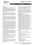
TAS5704 customer evaluation module (EVM) demonstrates the integrated circuit (IC) TAS5704 from
Texas Instruments (TI).
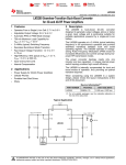
TAS5704 is a 4-channel device with an I2S/RJ/LJ digital audio stream input and amplified PWM signal
out. The subwoofer PWM signal is provided to an external class D power stage (TAS5601), which uses a
LC demodulation filter to drive a subwoofer. For detail information about the TAS5704 device review the
device data sheet, document number SLOS563.
TAS5704 is designed to drive two 8-Ω loudspeakers up to 20W per channel (10%THD+N) in a BTL
configuration. The TAS5704EVM can also be configured to drive four, 4-Ω speakers in a single-ended
(SE) configuration. Finally, the TAS5704EVM can be configured to drive 2 single-ended speakers plus 1
bridge-tied speaker (2.1 mode). Review the board schematic, and TAS5601 documents for additional
information and more specific application information on the subwoofer daughter card and connector.
TAS5704EVM, together with other TI components on this board, is a complete 4 channel digital audio
amplifier system, which includes digital input (SPDIF), analog inputs via ADC, and other features like
mute, power down, output configuration control, format control, and gain control.
Left
SPDIF/
Optical, Coax
I2S
Right
TAS5704
2CH Analog Input
from Other Source/
Digital Out
Subwofer
PWM out
TAS5601EVM2
Figure 1. 2-Channel (BTL) Configuration with External Subwoofer EVM (TAS5601EVM2)
SLOU224 – April 2008
Submit Documentation Feedback
TA5704EVM 4-Channel Digital Audio Power Amplifier with Hardware Control
7
Overview
www.ti.com
SPDIF/
Optical, Coax
LC +
Cap
Left
LC +
Cap
Right
I2S
TAS5704
2CH Analog Input
from Other Source/
Digital Out
Sub
LC
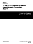
Figure 2. 2-Channel (SE) + 1-Channel (BTL) Configuration
SPDIF/
Optical, Coax
LC +
Cap
LFront
LC +
Cap
RFront
LC +
Cap
LRear
LC +
Cap
RRear
I2S
TAS5704
2CH Analog Input
from Other Source/
Digital Out
Figure 3. 4-Channel (SE) Configuration
1.1
TAS5704EVM Features
•
•
•
•
•
•
8
Self-contained protection systems and control pins
Standard I2S data input using optical or RCA inputs
Analog input through analog to digital converter
Subwoofer connection. PWM terminal to provide signal and power to an external subwoofer board
(TAS5601EVM2)
Double-sided plated-through PCB layout, 2oz copper, 2mm.
Access to control signal gain, output configuration, and data format on the EVM board using jumpers
TA5704EVM 4-Channel Digital Audio Power Amplifier with Hardware Control
SLOU224 – April 2008
Submit Documentation Feedback
System Interfaces
www.ti.com
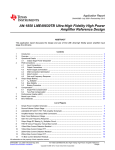
Figure 4. Top Composite View of TAS5704EVM
1.2
Basic Tools for Initial Board Power up
•
•
•
•
•
•
2
Up to 26V, 3A power supply (PVCC)
5V, 500mA power supply (VIN)
Banana cables for power supplies and speakers
Optical or coaxial cable for SPDIF interface based on signal source
Two 8Ω speakers (BTL) or 4Ω speakers (SE). Resistive loads can also be used
Optional: TAS5601EVM2 (for subwoofer connection when using BTL configuration)
System Interfaces
This chapter describes the TAS5704EVM board in regards to power supply (PSU) and system interfaces.
2.1
PSU Interface
The TAS5704EVM module is powered using two power supply sources a 10–26V (PVCC) power supply
and a 5V (VIN) power supply. The 3.3V voltage levels are generated on the board using voltage regulators
from VIN supply.
Note:
The length of power supply cable must be minimized. Increasing length of PSU cable is
equal to increasing the distortion for the amplifier at high output levels and low frequencies.
Maximum output stage supply voltage depends on the speaker load resistance. Check the recommended
maximum supply voltage in the TAS5704 data sheet (SLOS563).
SLOU224 – April 2008
Submit Documentation Feedback
TA5704EVM 4-Channel Digital Audio Power Amplifier with Hardware Control
9
System Interfaces
www.ti.com
Table 1. Recommended Power Supplies
Description
Voltage Limitations
(8 Ω load)
Current Recommendations
System power supply
5V
500 mA
Output power stage supply
10 – 26 V
3A (1)
(1)
2.2
The rated current correspond to 2 channels at 20W per channel.
PSC Connector
•
•
•
•
Connect the
Connect the
Connect the
PVCC.
Connect the
PGND.
positive node of the 5V (VIN) power supply to the red binding post marked VIN.
GND node of the 5V power supply to the black binding post marked GND
positive node of the high voltage power supply (PVCC) to the red binding post marked
negative node of the high voltage power supply (PGND) to the black binding post marked
There is no specific power up sequence for TAS5704, but it is recommended to power up the VIN
supply first while reset is kept low for at least 1ms and then power up the PVCC.
2.3
Loudspeaker and Subwoofer Connectors (2-Channel BTL Configuration)
CAUTION
Both positive and negative speaker outputs are floating and may not be
connected to ground (e.g. through an oscilloscope).
•
•
•
•
2.4
Connect the positive (+) and negative (–) nodes of the left speaker to the corresponding metal binding
post marked OUTA and OUTB on TAS5704EVM board.
Connect the positive (+) and negative (–) nodes of the right speaker to the corresponding metal
binding post marked OUTC and OUTD on TAS5704EVM board.
Install jumpers JP3–JP6 and JP7–JP10 for BTL configuration
The subwoofer is an option on this EVM, which is provided through connecting TAS5601EVM2 to the
TAS5704EVM using connector J1. Connector J1 provides the power and corresponding PWMs to the
TAS5601EVM2 (subwoofer amplifier). TAS5601EVM2 is configured in PBTL and is able to provide
40W to an 8-Ω speaker. Connect the subwoofer positive and negative nodes to the corresponding
metal binding posts on the TAS5601EVM2.
Digital Audio Interface SPDIF (J1/OPTO)
The Digital Audio Interface contains digital audio signal data (I2S). See TAS5704 Data sheet (SLOS563)
for signal timing and details not explained in this document.
RCA connector and OPTO connector are the two SPDIF interfaces. The switch S1 is used to toggle
between OPTO and RCA connector based on available signal source. Once the RCA cable or optical
cable is connected and the signal source is powered up, please verify the SPDIF lock indicator (blue
LED3) to make sure there is viable signal available to the device.
The format of the DIR9001 SPDIF receiver can be changed using jumpers FMT0 and FMT1. Jumpers
installed = 0. Jumpers removed = 1. The description of possible modes is printed on the EVM.
See the schematic of TAS5704EVM and the DIR9001 device for detail information on method by which
the data and clocks are provided to TAS5704.
10
TA5704EVM 4-Channel Digital Audio Power Amplifier with Hardware Control
SLOU224 – April 2008
Submit Documentation Feedback
Jumpers and Control Utilities
www.ti.com
2.5
ADC Interface
In the absence of digital signal source ADC (PCM1808) may be used to convert an analog audio signal to
digital signal and provide it to TAS5704. DIR9001 still provides clocks to ADC in this process. The
frequency of the oscillator selected for DIR 9001determinse the sampling frequency in the absence of
digital signal. If the OSC is 24MHz the sampling frequency will be set at 96kHz and if the OSC is selected
to be 12MHz the sampling frequency will be defaulted to 48kHz when there is no signal on SPDIF input
terminals. ADC is an additional feature to this board to provide flexibility in sourcing audio signal to
TAS5704. Please review the datasheet of PCM1808 for detail description of the ADC on this EVM.
2.6
Board Power up General Guidelines
After connecting the loud speakers (loads), power supply, and data line, power up the VIN power supply.
Then power up the PVCC power supply. It is recommended to set the PVCC level to 10 volts and then
ramp it up to 20 volts to verify the cable connection functionality. It is recommended to set the gain to
–3dB at start by having both GAIN (GAIN0 and GAIN1) jumpers inserted. Note that the gain settings
marked on the EVM are not correct. Please see Table 3 on the next page for the correct settings. Having
jumpers FM0 and FM1 inserted and FM2 removed sets the data format for the device to I2S format. Make
sure the SPDIF format jumpers, FMT0 and FMT1 are removed to set the receiver format to I2S. It is
important to note that a device RESET (S2 on the top of the board labeled MASTER RESET) needs to be
applied after each gain, format, or configuration change in order for the device to latch in the new settings.
Finally, install jumpers CFG1 and CFG2 in the Config Control to select 2-CH-BTL-AD mode.
3
Jumpers and Control Utilities
3.1
Clock Frequency Change Jumper
JP1: In the presence of a valid digital signal input, when SPDIF lock occurs, the user may use JP1 to
change LR clock and BIT clock. When a shunt is inserted, the SCKO = 512Fs and when the shunt is
removed the SCKO = 256Fs. Default is SCKO = 256Fs.
In the absence of a valid digital signal DIR9001 clock outputs switch to the frequency of crystal (Y1). If the
crystal is chosen to be 24MHz the LR clock will be 96KHz and if the crystal is chosen to be 12MHz the LR
clock will be 48kHz.
3.2
SPDIF/PSIA Utilization Jumpers
The jumpers MCLK, LRCK, SCLK, SDATA allow the user to switch between the internal clock and data
sources and external clock and data sources for instance PSIA (from AP instrument). The default
configuration of these jumpers is SPDIF as it is marked on the EVM with a white arrow. PSIA outputs may
be utilized using pins 2 and 3 of the jumpers. Keep in mind that pin 3 of each jumper is connected to
GND. Thus, the user must pay attention to the polarity of the PSIA output cables at the time of insertion.
3.3
Data Routing Jumpers
Jumpers SDIN1, SDIN2: These jumpers enable the user to assign a data source to TAS5704 SDIN1 and
SDIN2 pins. See Table 2.
Table 2. TAS5704 SDINx Data Source
Jumper JP15:SDIN1
Position
Jumper JP16:SDIN2
Position
1-2
1-2
ADC
ADC
1-2
2-3
SPDIF/PSIA
SPDIF/PSIA
2-3
1-2
SPDIF/PSIA
ADC
2-3
2-3
SPDIF/PSIA
SPDIF/PSIA
SLOU224 – April 2008
Submit Documentation Feedback
SDIN1 Source
SDIN2 Source
TA5704EVM 4-Channel Digital Audio Power Amplifier with Hardware Control
11
Jumpers and Control Utilities
3.4
www.ti.com
GAIN Jumpers
GAIN0 and GAIN1 jumpers enable the user to change the gain of the device. It is important to assert
RESET (S2 labeled MASTER RESET) after each gain change in order for the device to recognize the new
gain configuration. The truth table is shown below and also it is marked on the EVM board. However, the
gain settings are WRONG on the EVM silkscreen. Refer to Table 3 for the correct gain settings.
Table 3. TAS5704 Gain Configuration
3.5
Jumper GAIN1
Shunt IN = 0
Jumper GAIN0
Shunt OUT = 1
GAIN (dB)
0
0
–3
0
1
3
1
0
9
1
1
12
Data Format Jumpers
FM0, FM1, and FM2 are used to change the data format by which TAS5704 operates. FMT0 and FMT1
jumpers associated with DIR9001 in SPDIF interface enables the user to change the data format of
DIR9001 so that the data format is in sync with TAS5704 data format. Both TAS5704 and DIR9001 are
set by default to operate at 24-bit I2S format. It is important to assert RESET after each format change in
order for the device to recognize the format change. The truth tables below indicate the jumper
configuration and the data format of TAS5704 and DIR9001 (SPDIF).
Table 4. TAS5704 Data Format
FM1 (1)
FM0 (1)
DATA FORMAT
0
0
0
16BIT RJ
0
0
1
18BIT RJ
0
1
0
20BIT RJ
0
1
1
24BIT RJ
1
0
0
16 - 24BIT I2S (Default)
1
0
1
16 – 24bit RJ
1
1
0
RESERVED
1
1
1
TEST MODE
FM2
(1)
(1)
SHUNT IN = 0, SHUNT OUT = 1 (see schematics for details)
Table 5. DIR9001 SPDIF Output Data Format
FMT1
(1)
3.6
(1)
FMT0 (1)
DATA FORMAT
0
0
16BIT
0
1
24BIT RJ
1
0
24BIT LJ
1
1
24BIT I2S (Default)
SHUNT IN = 0, SHUNT OUT = 1 (See schematic for details)
CONFIG Jumpers
CFG1 and CFG2 jumpers are used to select the output configuration between single-ended outputs and
bridge-tied outputs or a combination of the two options. See Table 6 for summary of possible settings.
12
TA5704EVM 4-Channel Digital Audio Power Amplifier with Hardware Control
SLOU224 – April 2008
Submit Documentation Feedback
Jumpers and Control Utilities
www.ti.com
Table 6. TAS5704 Output Configuration
3.7
Jumper CFG2
Shunt IN = 0
Jumper CFG1
Shunt IN = 0
0
0
2-Channel BTL Mode (AD Modulation). Connect speakers across OUTA/OUTB and
OUTC/OUTD.
0
1
2-Channel BTL Mode (BD Modulation). Connect speakers across OUTA/OUTB and
OUTC/OUTD.
1
0
2-Channel SE Mode AND 1-Channel BTL Mode (AD Modulation). Connect Left/Right
speakers across OUTA/Center terminal (+ side of speaker connected to OUTA) and
OUTB/Center terminal (+ side of speaker connected to Center terminal). Connect Subwoofer
across OUTC/D. Remove jumpers JP3 – JP6.
1
1
4-Channel SE Mode (AD Modulation). Connect Speakers across OUTA/Center,
OUTB/Center and OUTC/Center, OUTD/Center. OUTB and OUTD are inverted
internally….connect “+” side of speaker to center terminal (GND) so that OUTB and OUTD
will be in phase with OUTA and OUTC. Remove jumpers JP3 – JP6 and JP7 – JP10.
GAIN (dB)
Switches
RESET is an active low function. Pressing master reset switch (S2) resets TAS5704 and DIR9001.
Releasing the switch will take the devices out of reset.
POWER DOWN function is an active low function. Pressing the power-down switch (S3) powers down
TAS5704 (outputs remain switching at 50% duty cycle). Releasing the switch will take the device out of
power down.
MUTE is an active low function. Pressing the mute switch (S4) mutes TAS5704. Releasing the switch will
take the device out of mute.
SLOU224 – April 2008
Submit Documentation Feedback
TA5704EVM 4-Channel Digital Audio Power Amplifier with Hardware Control
13
Board Layout, Bill of Material, and Schematics
4
Board Layout, Bill of Material, and Schematics
4.1
TAS5704EVM Board Layout, Top Composite View
www.ti.com
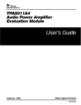
Figure 5. Top Layer Composite
14
TA5704EVM 4-Channel Digital Audio Power Amplifier with Hardware Control
SLOU224 – April 2008
Submit Documentation Feedback
Board Layout, Bill of Material, and Schematics
www.ti.com
4.2
TAS5704EVM Board Layout, Top Layer View
Figure 6. Top Layer
SLOU224 – April 2008
Submit Documentation Feedback
TA5704EVM 4-Channel Digital Audio Power Amplifier with Hardware Control
15
Board Layout, Bill of Material, and Schematics
4.3
www.ti.com
TAS5704EVM Board Layout, Bottom Layer View
Figure 7. Bottom Layer
16
TA5704EVM 4-Channel Digital Audio Power Amplifier with Hardware Control
SLOU224 – April 2008
Submit Documentation Feedback
Board Layout, Bill of Material, and Schematics
www.ti.com
4.4
Bill of Materials
Table 7. Bill of Materials for TAS5704EVM
Description
RefDes
QTY
MFR
MFR:Part No.
Vendor
Vendor Part No.
ALT Part No.
TI-SEMICONDUCTORS
Modulator/HBRIDGE
TQFP64-PAP
U1
1
Texas Instruments
TAS5704PAP
Texas
Instruments
TAS5704PAP
No ALT Part No.
Single Inverter Gate, SOT23-DBV5
INV1, INV2
2
Texas Instruments
SN74AHC1GU04DBVR
Digi-Key
296-1095-2
296-1095-1
Single 2 to 1 MUX W/Common Strobe,
TSSOP8-DCT
MUX
1
Texas Instruments
SN74LVC2G157DCTR
Digi-Key
296-13266-2
296-13266-1
Processor Supervisor Circuit, 3.3V
U3
1
Texas Instruments
TPS3825-33DBVT
Digi-Key
296-2636-2
296-2636-1
Voltage Regulator, LDO Fast Trans.
3.3Vdc 1.0A, SOP8-D
VR1
1
Texas Instruments
TPS76733QD
Digi-Key
296-2738-5
No ALT Part No.
S-Ended ANA-IN 24BIT 96kHz Stereo
ADC, TSSOP14-PW
ADC
1
Texas Instruments
PCM1808PW
Digi-Key
296-19773
No ALT Part No.
Digital Audio interface receiver
TSSOP28-PW
U2
1
TI - Burr Brown
DIR9001PW
Digi-Key
296-21389-5
No ALT Part No.
Optical receiver, 3.3V, PCB-RA ROHS
OPTO
1
Toshiba
TORX147LFT
Digi-Key
TORX147LFT
TORX141
Crystal, 12.288MHz, HC49US
Y1
1
ECS
ECS-122.8-S-4
Digi-Key
X174
No ALT Part No.
Transistor NPN 50V PreBiased/4.7K
100mA SOT23-DBV3
Q3
1
Diodes Inc.
DDTC143TCA-7
Digi-Key
DDTC143TCADITR
DDTC143TCADICT
Transistor PNP 50V PreBiased/4.7K
100mA SOT23-DBV3
Q1, Q2, Q4–Q6
5
Diodes Inc.
DDTA143TCA-7
Digi-Key
DDTA143TCADITR
DDTA143TCADICT
LED, Green 2.0V SMD0805
LED1, LED2,
LED4, LED5,
LED7
5
Lumex Optical
SML-LXT0805GW-TR
Digi-Key
67-1553-2
67-1553-1
LED, Red 2.0V SMD0805
LED9
1
Lumex Optical
SML-LXT0805IW-TR
Digi-Key
67-1552-2
67-1552-1
LED, Yellow 2.0V SMD0805
LED6, LED8,
LED10
3
Lumex Optical
SML-LXT0805YW-TR
Digi-Key
67-1554-2
67-1554-1
LED, Blue SM1206
LED3
1
Avago
Technologies
HSMR-C150
Digi-Key
516-1436-2
516-1436-1
CAP 33pF 50V CERM 0603 NPO
C64, C65
2
Panasonic
ECJ-1VC1H330J
Digi-Key
PCC330ACVTR
PCC330ACVCT
CAP 4700pF 50V CERM 0603 X7R
C42, C43, C61
3
Panasonic
ECJ-1VB1H472K
Digi-Key
PCC1780TR
PCC1780CT
CAP 0.01µF 16V CERM 0603 X7R
C78, C91
2
Murata Electronics
GRM188R71C103KA01D
Digi-Key
490-1525-2
490-1525-1
CAP 0.01µF 50V CERM 0603 X7R
C7
1
Panasonic
ECU-V1H103KBV
Digi-Key
PCC103BVTR
PCC103BVCT
CAP 0.047µF 16V CERM 0603 X7R
C10, C41, C88,
C89
4
Panasonic
ECJ-1VB1C473K
Digi-Key
PCC1758TR
PCC1758CT
CAP 0.068µF 16V CERM 0603 X7R
C63
1
Panasonic
ECJ-1VB1C683K
Digi-Key
PCC1760TR
PCC1760CT
CAP 0.1µF 16V CERM 0603 X7R
C5, C8, C11,
C25, C55,
C66–C68, C70,
C71, C73,
C80–C83, C90,
C93
17
Panasonic
ECJ-1VB1C104K
DIGI-KEY
PCC1762TR
PCC1762CT
CAP 0.1µF 50V CERM 0603 X7R
C9, C47
2
Murata
GRM188R71H104KA93D
Digi-Key
490-1519-2
490-1519-1
CAP 0.22µF 25V CERM 0603 X7R
C1, C16, C23,
C26
4
Murata Electronics
GRM188R71E224KA88D
Digi-Key
490-3290-2
490-3290-1
CAP 1.0µF 25V CERM 0603 X5R
C2, C18, C24
3
Panasonic
ECJ-1VB1E105K
Digi-Key
PCC2422TR
PCC2422CT
CAP 4.7µF 6.3V CERM 0603 X5R
C13
1
TDK Corp.
C1608X5R0J475M
Digi-Key
445-1417-2
445-1417-1
CAP 0.1µF50V CERM 0805 X7R
C15, C29, C35,
C44
4
Panasonic
ECJ-2YB1H104K
Digi-Key
PCC1840TR
PCC1840CT
0
Taiyo Yuden
UMK212F105ZG-T
Digi-Key
587-1308-2
587-1308-1
4
EPCOS
B32529C5105J
Digi-Key
495-1087
B32529C105J
SEMICONDUCTORS
CAPACITORS
CAP 1.0µF 50V CERM 0805 Y5V
CAP 1.0µF 50V METAL Polyester film
MKT
C48–C50, C79
CAP 1µF 50V RAD ALUM ELEC FC
C86, C87
2
Panasonic
EEU-FC1H1R0
Digi-Key
P10312
No ALT Part No.
CAP 10µF 16V RAD ALUM ELEC KGA
C46, C53, C54,
C57, C69, C72,
C74, C76, C84,
C85, C92
11
Panasonic
ECE-A1CKG100
Digi-Key
P910
No ALT Part No.
CAP 15µF 50V RAD ALUM ELEC FC
C37
1
Panasonic
EEU-FC1H150
Digi-Key
P10317
No ALT Part No.
CAP 22µF 10V RAD ALUM ELEC KGA
C6, C60
2
Panasonic
ECE-A1AKG220
Digi-Key
P905
No ALT Part No.
CAP 47µF 16V RAD ALUM ELEC FC
C4
1
Panasonic
EEU-FC1C470
Digi-Key
P11196
No ALT Part No.
CAP 220µF 50V RAD ALUM ELEC FC
C3, C28, C36,
C38
4
Panasonic
EEU-FC1H221
Digi-Key
P10325
No ALT Part No.
CAP 470µF 50V RAD ALUM ELEC FC
C58, C59
2
Panasonic
EEU-FC1H471L
Digi-Key
P11260
No ALT Part No.
SLOU224 – April 2008
Submit Documentation Feedback
TA5704EVM 4-Channel Digital Audio Power Amplifier with Hardware Control
17
Board Layout, Bill of Material, and Schematics
www.ti.com
Table 7. Bill of Materials for TAS5704EVM (continued)
Description
RefDes
MFR
MFR:Part No.
Vendor
Vendor Part No.
ALT Part No.
CAP 1000µF 35V RAD ALUM ELEC FC
C51, C52, C62,
C75
QTY
4
Panasonic
EEU-FC1V102
Digi-Key
P10305
No ALT Part No.
RES 0.0 Ω 1/16W 5% SMD 0603
R29, R32, R35
3
Panasonic
ERJ-3GEY0R00V
Digi-Key
P0.0GTR
P0.0GCT
RES 3.3 Ω 1/16W 5% SMD 0603
R11, R13–R15
4
Yageo
9C06031A3R30JLHFT
Digi-Key
311-3.3GTR
311-3.3GCT
RES 47 Ω 1/16W 5% SMD 0603
R8, R16, R30,
R43, R44, R47,
R48, R57
8
Yageo
9C06031A47R0JLHFT
Digi-Key
311-47GTR
311-47GCT
RES 75.0 Ω 1/16W 1% SMD 0603
R49
1
Panasonic
ERJ-3EKF75R0V
Digi-Key
P75.0HTR
P75.0HCT
RES 100 Ω 1/16W 5% SMD 0603
R58, R59, R64,
R65
4
Yageo
9C06031A1000JLHFT
Digi-Key
311-100GTR
311-100GCT
RES 470 Ω 1/10W 5% SMD 0603
R7, R9, R40
3
Panasonic
ERJ-3GEYJ471V
Digi-Key
P470GTR
P470GCT
RES 332 Ω 1/16W 1% SMD 0603
R4, R5, R26,
R55, R56
5
Panasonic
ERJ-3EKF3320V
Digi-Key
P332HTR
P332HCT
RES 392 Ω 1/10W 1% SMD 0603
R3, R45, R70
3
Panasonic
ERJ-3EKF3920V
Digi-Key
P392HTR
P392HCT
RES 510 Ω 1/10W 5% SMD 0603
R28
1
Yageo
9C06031A5100JLHFT
Digi-Key
311-510GTR
311-510GCT
RES 680 Ω 1/10W 5% SMD 0603
R42
1
Yageo
9C06031A6800JLHFT
Digi-Key
311-680GTR
311-680GCT
RES 1kΩ 1/16W 5% SMD 0603
R54
1
Yageo
9C06031A1001JLHFT
Digi-Key
311-1.0KGTR
311-1.0KGCT
RES 2.00kΩ 1/16W 1% SMD 0603
R67
1
Panasonic
ERJ-3EKF2001V
Digi-Key
P2.00KHTR
P2.00KHCT
RES 2.49kΩ 1/16W 1% SMD 0603
R62
1
Panasonic
ERJ-3EKF2491V
Digi-Key
P2.49KHTR
P2.49KHCT
RES 4.99kΩ 1/16W 1% SMD 0603
R31, R39, R41,
R46, R63, R1,
R2, R12, R38
5
Panasonic
ERJ-3EKF4991V
Digi-Key
P4.99KHTR
P4.99KHCT
RES 7.50kΩ 1/16W 1% SMD 0603
R68
1
Panasonic
ERJ-3EKF7501V
Digi-Key
P7.50KHTR
P7.50KHCT
RES 10kΩ 1/16W 5% SMD 0603
R18–R25, R27,
R36, R50–R53,
R69
15
Panasonic
9C06031A1002JLHFT
Digi-Key
311-10KGTR
311-10KGCT
RES 18.2kΩ 1/10W 1% SMD 0603
R17
1
Yageo
9C06031A1822FKHFT
Digi-Key
311-18.2KHTR
311-18.2KHCT
RES 249kΩ 1/16W 1% SMD 0603
R61
1
Panasonic
ERJ-3EKF2493V
Digi-Key
P249KHTR
P249KHCT
RES 1.00MΩ 1/16W 1% SMD 0603
R66
1
Panasonic
ERJ-3EKF1004V
Digi-Key
P1.00MHTR
P1.00MHCT
RES 0.0 Ω 1/10W 5% SMD 0805
R10, R60
2
Panasonic
ERJ-GEY0R00V
Digi-Key
P0.0ATR
P0.0ACT
RES 3.3 Ω 1/10W 5% SMD 0805
R34
1
Panasonic
ERJ-6RQJ3R3V
Digi-Key
P3.3BTR
P3.3BCT
0
Panasonic
ERJ-6ENF1003V
Digi-Key
P100KCTR
P100KCCT
RESISTORS
RES 100kΩ 1/10W 1% SMD 0805
RES 0.0 Ω 1/8W 5% SMD 1206
R37
1
Panasonic
ERJ-8GEY0R00V
Digi-Key
P0.0ETR
P0.0ECT
RES 3.3 Ω 1/4W 5% SMD 1206
R6
1
Panasonic
ERJ-8RQJ3R3V
Digi-Key
P3.3PTR
P3.3PCT
RES 4.7 Ω 1/8W 5% SMD 1206
R33
1
Panasonic
ERJ-8RQJ4R7V
Digi-Key
P4.7PTR
P4.7PCT
Toko
America
A7503AY-150M
No ALT Part No.
FERRITES AND INDUCTORS
Inductor, series 11RHBP, 15UH
L1–L4
Header, 2 Pin Male, Straight, Gold
JP1–JP10,
CFG1
4
Toko America
A7503AY-150M
HEADERS AND JACKS
Sullins
PZC02SAAN
Digi-Key
S1011-02
No ALT Part No.
CFG2, FM0,
FM1, FMT0,
FMT1, FM2,
GAIN0, GAIN1
19
Sullins
PZC02SAAN
Digi-Key
S1011-02
No ALT Part No.
Header, 3 Pin Male, Straight, Gold
JP11–JP16
6
Sullins
PZC03SAAN
Digi-Key
S1011-03
No ALT Part No.
Socket header, 2x8 Pin Female Gold
PCB-RA
J1
1
Samtec
SSW-108-02-G-D-RA
Samtec
SSW-108-02-G-D-RA
No ALT Part No.
JACK, RCA, PCB-RA, ECONO All-metal
RCA
1
CUI Stack
RCJ-017
Digi-Key
CP-1466
No ALT Part No.
Jack, RCA, PCB-Vertical, Black
LIN, RIN
2
CUI Stack
RCJ-051
Digi-Key
CP-1424
No ALT Part No.
Digi-Key
S9001
No ALT Part No.
Digi-Key
5003K
No ALT Part No.
SHUNTS
Shunt, Black AU Flash 0.100
JP2,
JP11(1-2),
JP12(1-2),
JP13(1-2),
JP14(1-2)
JP15(2-3),
JP16(2-3),
GAIN0, GAIN1,
FM0, FM1
PC Testpoint, Orange
BKNDERR,
LRCLK, MCLK,
MUTE, PDN,
RESET, SCLK
11
Sullins
SPC02SYAN
TESTPOINTS AND SWITCHES
18
Keystone
Electronics
5003
TA5704EVM 4-Channel Digital Audio Power Amplifier with Hardware Control
SLOU224 – April 2008
Submit Documentation Feedback
Board Layout, Bill of Material, and Schematics
www.ti.com
Table 7. Bill of Materials for TAS5704EVM (continued)
Description
RefDes
MFR
MFR:Part No.
Vendor
Vendor Part No.
ALT Part No.
SHUTDOWN,
SUBM, SUBP,
VALID
QTY
11
Keystone
Electronics
5003
Digi-Key
5003K
No ALT Part No.
Switch, Momentary SMT-Short, Black
Tab, 160g
S2–S4
3
Panasonic
EVQ-PPBA25
Digi-Key
P8086STR
P8086SCT
Switch, SPST, VERT-PCB ROHS
S1
1
NKK Switches
G12AP-RO
Digi-Key
360-1758
360-1701
Mouser
566-8019
No ALT Part No.
NON-INSULATED WIRE GROUND LOOPS
Non-insulated bus wire, 10MM Length,
18 AWG
PGND, PGND
2
Belden CDT
8019000100
Bend the wire lengths into a 'U' shape and solder to the board. Leave a gap of around 0.3 inch between the board and the wire.
BINDING POSTS
Binding post, 15A, uninsulated
OUTA, OUTB,
OUTC, OUTD,
GND, GND
6
Johnson
Components
111-2223-001
Digi-Key
J587
No ALT Part No.
Binding post, Red, 15A ECONO
PVCC, VIN
2
Keystone
Electronics
7006
Digi-Key
7006K
No ALT Part No.
Binding post, Black, 15A ECONO
PGND,
GND(PGND)
2
Keystone
Electronics
7007
Digi-Key
7007K
No ALT Part No.
Standoff 4-40 Threaded M/F 0.75 in.
ALUM-HEX
HW1–HW6
6
Keystone
Electronics
8403K
Digi-Key
8403K
No ALT Part No.
Hex Nut, 4-40, Zinc/Steel
HW1–HW6
6
Building Fasteners
HNZ440
Digi-Key
H216
No ALT Part No.
STANDOFFS AND HARDWARE
Component Count: 262
COMPONENTS NOT ASSEMBLED
C77, C14, C32, C39, C40, C30, C45, C56, C31, C33, C12, C19, C27, C34, C17, C20, C21, C22, R11, R13, R14, R15
4.5
Schematic
The schematics are appended to this document.
SLOU224 – April 2008
Submit Documentation Feedback
TA5704EVM 4-Channel Digital Audio Power Amplifier with Hardware Control
19
SPDIF RECEIVER
ENGINEERING EVALUATION ONLY
SPDIF
LOCK
U2
SPDIF FORMAT
RCA INPUT
DATA FORMAT FMT1 FMT0
16Bit/MSB/RJ
24Bit/MSB/RJ
24Bit/MSB/LJ
24Bit/MSB/I2S
OPTO INPUT
L
L
H
H
L
H
L
H
SHUNTS IN = 0
SHUNTS OUT = 1
JUMPER NOTES
1-2: SPDIF CLOCKS/DATA
2-3: CLOCKS/DATA = PSIA
(MCLK)
DIR9001PW
TO
TAS5704
(SDATA)
JP1 IN: SCKO = 512 Fs
JP1 OUT: SCKO = 256 Fs (DEFAULT)
(SCLK)
(LRCLK)
SPDIF
INPUT
SELECT
JUMPER NOTES
1-2: OPTO INPUT
2-3: COAX INPUT
1-2: SPDIF CLOCKS/DATA (DEFAULT)
2-3: CLOCKS/DATA = PSIA
TO
ADC
OPTO
INPUT
COAX
INPUT
FROM MASTER RESET
DECOUPLING
DECOUPLING
TI
CX
PROJECT: TAS5704
EVALUTION MODULE
Design Team: RYAN KEHR
Mod: NC PCB Rev: NC Sheet 1 of 6
Schematic Rev: NC
Save Date: JULY 10, 2007
Print Date Tue Jul 10, 2007
Filename:
TAS5704EVM.SCH
Drawn By: LDN
ANALOG TO DIGITAL CONVERTER
ENGINEERING EVALUATION ONLY
ANALOG INPUTS
ADC
SDIN CONFIGURATOR
JP16 NOTE
1-2: SDIN2 = ADC (DEFAULT)
2-3: SDIN2 = SPDIF/PSIA
FROM
SPDIF
TO
TAS5704
PCM1808PW
JP15 NOTE
3.3V DECOUPLING
5V DECOUPLING
1-2: SDIN1 = SDIN2
2-3: SDIN1 = SPDIF/PSIA (DEFAULT)
TI
CX
PROJECT: TAS5704
Design Team: RYAN KEHR
Mod: NC
Schematic Rev: NC
Save Date: JULY 10, 2007
Filename:
TAS5704EVM.SCH
EVALUTION MODULE
PCB Rev: NC
Sheet 2 of 6
Print Date Tue Jul 10, 2007
Drawn By: LDN
TAS5704 I/O
ENGINEERING EVALUATION ONLY
3.3V DECOUPLING
MASTER RESET
TO SPDIF
MUTE
PGND
SE
BTL
BLT=SHUNTS IN
SE=SHUNTS OUT
POWER
DOWN
FROM
SPDIF
PGND
MUTE
SE
BLT=SHUNTS IN
SE=SHUNTS OUT
PGND
U1
TAS5704PAP
FROM
ADC
SE
BTL
BLT=SHUNTS IN
SE=SHUNTS OUT
PGND
GAIN CONTROL
GAIN1 GAIN0 CHANNEL GAIN (dB)
0
0
20 DEFAULT
0
1
26
1
0
32
1
1
36
SE
BLT=SHUNTS IN
SE=SHUNTS OUT
PGND
FORMAT CONTROL
FM2
0
0
0
0
1
1
1
1
FM1
0
0
1
1
0
0
1
1
FM0 SERIAL DATA FORMAT
16Bit RJ
0
18Bit RJ
1
20Bit RJ
0
24Bit RJ
1
16-24Bit I2S(DEFAULT)
0
16-24Bit LJ
1
RESERVED
0
TEST MODE
1
FROM
SPDIF
PGND
DEFAULT JUMPERED TO 4xSE MODE
CONFIG CONTROL
CFG2
0
0
1
1
CFG1
0
1
0
1
OUTPUT MODE
2CH/BTL/AD
2CH/BTL/BD
2.1CH/2xSE/1xBTL
4CH/4xSE(DEFAULT)
TO SUBWOOFER CONNECTOR
PGND
FROM SUBWOOFER DAUGHTERCARD
VALID
SHUTDOWN
TI
CX
PROJECT: TAS5704
EVALUTION MODULE
Design Team: RYAN KEHR
Mod: NC PCB Rev: NC Sheet 3 of 6
Schematic Rev: NC
Save Date: JULY 10, 2007
Print Date Tue Jul 10, 2007
Filename:
TAS5704EVM.SCH
Drawn By: LDN
POWER SUPPLIES
ENGINEERING EVALUATION ONLY
TO SUBWOOFER DAUGHTERCARD
HIGH VOLTAGE
POWER INPUTS
EMI
SNUBBERS
TO TAS5704
PVCC = 10-26V
TO SUBWOOFER DAUGHTERCARD
TO TAS5704
TO SPDIF
TO ADC
LOW VOLTAGE
POWER INPUTS
3.3V@1A
SUBWOOFER CONNECTOR
FROM
P.S.
TO/FROM
TAS5704
TO ADC
BOM ONLY
TO
SUBWOOFER
DAUGHTERCARD
(TAS5601EVM2)
PGND
TI
CX
PROJECT: TAS5704
EVALUTION MODULE
Design Team: RYAN KEHR
Mod: NC PCB Rev: NC Sheet 4 of 6
Schematic Rev: NC
Save Date: JULY 10, 2007
Print Date Tue Jul 10, 2007
Filename:
TAS5704EVM.SCH
Drawn By: LDN
REVISION CHANGES
REVISION
NC
DESCRIPTION
PRE-RELEASE
ENGINEERING EVALUATION ONLY
DATE
10JUL2007
APPROVAL
RK
TI
CX
PROJECT: TAS5704
EVALUTION MODULE
Design Team: RYAN KEHR
Mod: NC PCB Rev: NC Sheet 5 of 6
Schematic Rev: NC
Save Date: JULY 10, 2007
Print Date Tue Jul 10, 2007
Filename:
TAS5704EVM.SCH
Drawn By: LDN
TEXAS INSTRUMENTS DISCLAIMER
ENGINEERING EVALUATION ONLY
DISCLAIMER
The information and materials ("Materials") provided here are provided by Texas Instruments Incorporated ("TI") as
a service to its customers and/or suppliers, and may be used for informational purposes only, and only subject to
the following terms. By downloading or viewing these Materials, you are signifying your assent to these terms.
1.) These preliminary evaluation schematics are intended for use for PRELIMINARY ENGINEERING DEVELOPMENT
AND EVALUATION PURPOSES ONLY and are not considered by Texas Instruments to be fit as a basis for
establishing production products or systems. This information may be incomplete in several respects, including but
not limited to information relating to required design, marketing, and/or manufacturing-related protective considerations
and product safety measures typically found in the end-product incorporating the goods.
2.) Accordingly, neither TI nor its suppliers warrant the accuracy or completeness of the information, text, graphics,
links or other items contained within the Materials. TI may make changes to the Materials, or to the products described
therein, at any time without notice. TI makes no commitment to update the Materials.
3.) TI assumes no liability for applications assistance, customer product design, software performance, or services that
may be described or referenced in the Materials. The user assumes all responsibility and liability for proper and safe
design and handling of goods. Accordingly, the user indemnifies TI from all claims arising from its use of the Materials.
4.) TI currently deals with various customers for products, and therefore our arrangement with the user will not be
exclusive. TI makes no representations regarding the commercial availability of non-TI components that may be
referenced in the Materials.
5.) No license is granted under any patent right or other intellectual property right of TI covering or relating to any
combination, machine, or process in which such TI products or services might be or are used. Except as expressly
provided herein, TI and its suppliers do not grant any express or implied right to you under any patents, copyrights,
trademarks, or trade secret information.
6.) Performance tests and ratings, to the extent referenced in the Materials, are measured using specific computer
systems and/or components and reflect the approximate performance of TI products as measured by those tests. Any
difference in system hardware or software design or configuration may affect actual performance. Buyers should consult
other sources of information to evaluate the performance of systems or components they are considering purchasing.
7.) Resale of TI's products or services with statements different from or beyond the parameters stated by TI for that
product or service in official TI data books or data sheets voids all express and any implied warranties for the associated
TI product or service, and is an unfair and deceptive business practice, and TI is not responsible for any such use.
8.) The Materials are copyrighted and any unauthorized use may violate copyright, trademark, and other laws. You may
only download one copy for your internal use only, unless you are specifically licensed to do otherwise by TI in writing.
This is a license, not a transfer of title, and is subject to the following restrictions: You may not:
(a) modify the Materials (including any associated warranties, conditions, limitations or
notices) or use them for any commercial purpose, or any public display, performance, sale or
rental;
(b) decompile, reverse engineer, or disassemble software Materials except and only to the
extent permitted by applicable law;
(c) remove any copyright or other proprietary notices from the Materials;
(d) transfer the Materials to another person. You agree to prevent any unauthorized copying
of the Materials. TI may terminate this license at any time if you are in breach of the terms
of this Agreement. Upon termination, you will immediately
destroy the Materials.
9.) THE MATERIALS ARE PROVIDED "AS IS" WITHOUT ANY EXPRESS OR IMPLIED WARRANTY OF ANY KIND
INCLUDING WARRANTIES OF MERCHANTABILITY, NONINFRINGEMENT OF INTELLECTUAL PROPERTY, OR
FITNESS FOR ANY PARTICULAR PURPOSE. IN NO EVENT SHALL TI OR ITS SUPPLIERS BE LIABLE FOR ANY
DAMAGES WHATSOEVER (INCLUDING, WITHOUT LIMITATION, DAMAGES FOR LOSS OF PROFITS, BUSINESS
INTERRUPTION, LOSS OF INFORMATION) ARISING OUT OF THE USE OF OR INABILITY TO USE THE
MATERIALS, EVEN IF TI HAS BEEN ADVISED OF THE POSSIBILITY OF SUCH DAMAGES.
TI
EVALUATION BOARD/KIT IMPORTANT NOTICE
Texas Instruments (TI) provides the enclosed product(s) under the following conditions:
This evaluation board/kit is intended for use for ENGINEERING DEVELOPMENT, DEMONSTRATION, OR EVALUATION PURPOSES
ONLY and is not considered by TI to be a finished end-product fit for general consumer use. Persons handling the product(s) must have
electronics training and observe good engineering practice standards. As such, the goods being provided are not intended to be complete
in terms of required design-, marketing-, and/or manufacturing-related protective considerations, including product safety and environmental
measures typically found in end products that incorporate such semiconductor components or circuit boards. This evaluation board/kit does
not fall within the scope of the European Union directives regarding electromagnetic compatibility, restricted substances (RoHS), recycling
(WEEE), FCC, CE or UL, and therefore may not meet the technical requirements of these directives or other related directives.
Should this evaluation board/kit not meet the specifications indicated in the User’s Guide, the board/kit may be returned within 30 days from
the date of delivery for a full refund. THE FOREGOING WARRANTY IS THE EXCLUSIVE WARRANTY MADE BY SELLER TO BUYER
AND IS IN LIEU OF ALL OTHER WARRANTIES, EXPRESSED, IMPLIED, OR STATUTORY, INCLUDING ANY WARRANTY OF
MERCHANTABILITY OR FITNESS FOR ANY PARTICULAR PURPOSE.
The user assumes all responsibility and liability for proper and safe handling of the goods. Further, the user indemnifies TI from all claims
arising from the handling or use of the goods. Due to the open construction of the product, it is the user’s responsibility to take any and all
appropriate precautions with regard to electrostatic discharge.
EXCEPT TO THE EXTENT OF THE INDEMNITY SET FORTH ABOVE, NEITHER PARTY SHALL BE LIABLE TO THE OTHER FOR ANY
INDIRECT, SPECIAL, INCIDENTAL, OR CONSEQUENTIAL DAMAGES.
TI currently deals with a variety of customers for products, and therefore our arrangement with the user is not exclusive.
TI assumes no liability for applications assistance, customer product design, software performance, or infringement of patents or
services described herein.
Please read the User’s Guide and, specifically, the Warnings and Restrictions notice in the User’s Guide prior to handling the product. This
notice contains important safety information about temperatures and voltages. For additional information on TI’s environmental and/or
safety programs, please contact the TI application engineer or visit www.ti.com/esh.
No license is granted under any patent right or other intellectual property right of TI covering or relating to any machine, process, or
combination in which such TI products or services might be or are used.
FCC Warning
This evaluation board/kit is intended for use for ENGINEERING DEVELOPMENT, DEMONSTRATION, OR EVALUATION PURPOSES
ONLY and is not considered by TI to be a finished end-product fit for general consumer use. It generates, uses, and can radiate radio
frequency energy and has not been tested for compliance with the limits of computing devices pursuant to part 15 of FCC rules, which are
designed to provide reasonable protection against radio frequency interference. Operation of this equipment in other environments may
cause interference with radio communications, in which case the user at his own expense will be required to take whatever measures may
be required to correct this interference.
EVM WARNINGS AND RESTRICTIONS
It is important to operate this EVM within the input voltage range (PVCC and VIN, correspondingly) of 26 V at 3 A, 5 V at 500 mA and
output power of 20 W maximum.
Exceeding the specified input range may cause unexpected operation and/or irreversible damage to the EVM. If there are questions
concerning the input range, please contact a TI field representative prior to connecting the input power.
Applying loads outside of the specified output range may result in unintended operation and/or possible permanent damage to the EVM.
Please consult the EVM User's Guide prior to connecting any load to the EVM output. If there is uncertainty as to the load specification,
please contact a TI field representative.
During normal operation, some circuit components may have case temperatures greater than 60°C. The EVM is designed to operate
properly with certain components above 60°C as long as the input and output ranges are maintained. These components include but are
not limited to linear regulators, switching transistors, pass transistors, and current sense resistors. These types of devices can be identified
using the EVM schematic located in the EVM User's Guide. When placing measurement probes near these devices during operation,
please be aware that these devices may be very warm to the touch.
Mailing Address: Texas Instruments, Post Office Box 655303, Dallas, Texas 75265
Copyright 2008, Texas Instruments Incorporated
IMPORTANT NOTICE
Texas Instruments Incorporated and its subsidiaries (TI) reserve the right to make corrections, modifications, enhancements, improvements,
and other changes to its products and services at any time and to discontinue any product or service without notice. Customers should
obtain the latest relevant information before placing orders and should verify that such information is current and complete. All products are
sold subject to TI’s terms and conditions of sale supplied at the time of order acknowledgment.
TI warrants performance of its hardware products to the specifications applicable at the time of sale in accordance with TI’s standard
warranty. Testing and other quality control techniques are used to the extent TI deems necessary to support this warranty. Except where
mandated by government requirements, testing of all parameters of each product is not necessarily performed.
TI assumes no liability for applications assistance or customer product design. Customers are responsible for their products and
applications using TI components. To minimize the risks associated with customer products and applications, customers should provide
adequate design and operating safeguards.
TI does not warrant or represent that any license, either express or implied, is granted under any TI patent right, copyright, mask work right,
or other TI intellectual property right relating to any combination, machine, or process in which TI products or services are used. Information
published by TI regarding third-party products or services does not constitute a license from TI to use such products or services or a
warranty or endorsement thereof. Use of such information may require a license from a third party under the patents or other intellectual
property of the third party, or a license from TI under the patents or other intellectual property of TI.
Reproduction of TI information in TI data books or data sheets is permissible only if reproduction is without alteration and is accompanied
by all associated warranties, conditions, limitations, and notices. Reproduction of this information with alteration is an unfair and deceptive
business practice. TI is not responsible or liable for such altered documentation. Information of third parties may be subject to additional
restrictions.
Resale of TI products or services with statements different from or beyond the parameters stated by TI for that product or service voids all
express and any implied warranties for the associated TI product or service and is an unfair and deceptive business practice. TI is not
responsible or liable for any such statements.
TI products are not authorized for use in safety-critical applications (such as life support) where a failure of the TI product would reasonably
be expected to cause severe personal injury or death, unless officers of the parties have executed an agreement specifically governing
such use. Buyers represent that they have all necessary expertise in the safety and regulatory ramifications of their applications, and
acknowledge and agree that they are solely responsible for all legal, regulatory and safety-related requirements concerning their products
and any use of TI products in such safety-critical applications, notwithstanding any applications-related information or support that may be
provided by TI. Further, Buyers must fully indemnify TI and its representatives against any damages arising out of the use of TI products in
such safety-critical applications.
TI products are neither designed nor intended for use in military/aerospace applications or environments unless the TI products are
specifically designated by TI as military-grade or "enhanced plastic." Only products designated by TI as military-grade meet military
specifications. Buyers acknowledge and agree that any such use of TI products which TI has not designated as military-grade is solely at
the Buyer's risk, and that they are solely responsible for compliance with all legal and regulatory requirements in connection with such use.
TI products are neither designed nor intended for use in automotive applications or environments unless the specific TI products are
designated by TI as compliant with ISO/TS 16949 requirements. Buyers acknowledge and agree that, if they use any non-designated
products in automotive applications, TI will not be responsible for any failure to meet such requirements.
Following are URLs where you can obtain information on other Texas Instruments products and application solutions:
Products
Amplifiers
Data Converters
DSP
Clocks and Timers
Interface
Logic
Power Mgmt
Microcontrollers
RFID
RF/IF and ZigBee® Solutions
amplifier.ti.com
dataconverter.ti.com
dsp.ti.com
www.ti.com/clocks
interface.ti.com
logic.ti.com
power.ti.com
microcontroller.ti.com
www.ti-rfid.com
www.ti.com/lprf
Applications
Audio
Automotive
Broadband
Digital Control
Medical
Military
Optical Networking
Security
Telephony
Video & Imaging
Wireless
www.ti.com/audio
www.ti.com/automotive
www.ti.com/broadband
www.ti.com/digitalcontrol
www.ti.com/medical
www.ti.com/military
www.ti.com/opticalnetwork
www.ti.com/security
www.ti.com/telephony
www.ti.com/video
www.ti.com/wireless
Mailing Address: Texas Instruments, Post Office Box 655303, Dallas, Texas 75265
Copyright © 2008, Texas Instruments Incorporated