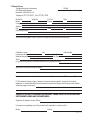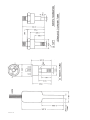
1
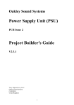
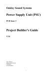
INSTRUCTION
MANUAL
MODEL HVC
-282
HVC-282
VACUUM CONTROLLER
Manual Print History
The print history shown below lists the printing dates of all revisions and addenda created for this
manual. The revision level letter increases alphabetically as the manual undergoes subsequent
updates. Addenda, which are released between revisions, contain important change information that
the user should incorporate immediately into the manual. Addenda are numbered sequentially.
When a new revision is created, all addenda associated with the previous revision of the manual are
incorporated into the new revision of the manual. Each new revision includes a revised copy of this
print history page.
Revision A (Document Number 129-051994) ................................................................ May 1994
Revision B (Document Number 129-082002) ............................................................. August 2002
CAUTION
Refer to accompanying documents for electrical connections.
designed for class II installations.
Hastings Instruments reserves the right to change or modify the design of its equipment without
any obligation to provide notification of change or intent to change.
TABLE OF CONTENTS
SECTION 1.0
GENERAL INFORMATION........................................................................................... 5
1.1 Descripion......................................................................................................................... 5
1.2 Operating Principle ..................................................................................................................................... 5
1.3 Specifications ............................................................................................................................................ 5
1.4 Accessories ................................................................................................................................................ 6
SECTION 2.0
GAUGE TUBES AND CABLES .......................................................................................... 7
2.1 Gauge Tubes ............................................................................................................................................... 7
2.2 Gauge Tube Cables ..................................................................................................................................... 7
SECTION 3.0 INSTALLATION PROCEDURE ........................................................................................... 8
3.1 Panel Mounting .......................................................................................................................................... 8
3.2 Gauge Tube Installation .............................................................................................................................. 8
SECTION 4.0 OPERATION ....................................................................................................................... 9
SECTION 5.0 CALIBRATION AND TROUBLESHOOTING GUIDE ............................................................ 10
5.1 Checking of Tube ........................................................................................................................................ 10
5.2 Calibration of Gauge and Gauge Tube ........................................................................................................ 10
5.3 Check Against Primary Standard ................................................................................................................ 11
SECTION 6.0 NOTES ON VACUUM MEASUREMENT .............................................................................. 12
6.1 Effects of Condensable Vapors ................................................................................................................... 12
6.2 Outgassing ................................................................................................................................................. 12
6.3 Effect of Thermal Conductivity ..................................................................................................................... 12
6.4 Effects of System Conductance .................................................................................................................. 12
SECTION 7.0 SERVICE INFORMATION ..................................................................................................... 13
7.1 Warranty Repair Policy ................................................................................................................................ 13
7.2 Non-Warranty Repair Policy ......................................................................................................................... 13
7.3 Service Form ............................................................................................................................................... 15
SECTION 8.0 DRAWINGS AND DIAGRAMS .............................................................................................. 17
PAGE 4
1.0 GENERAL INFORMATION
This manual contains technical and general information concerning the installation, operation and calibration of the Hastings
HVC-282 Vacuum Gauge, and associated components.
For proper operation, the Hastings HVC-282 Vacuum Gauge must be suitably connected to a Hastings Model DV-273 Gauge
Tube. Attempting to use this Vacuum Gauge with any other transducer may damage the gauge and or transducer.
1.1 Description:
The HVC-282 vacuum instrument offers a digital readout of 0-20 Torr with 0.01 Torr resolution with two adjustable set point
relays, using a international input power supply for 115/220VAC 50/60Hz operation depending on internal switch configuration (Please see Sec. 4.0), all in a standard Hastings VT Gauge unit. The DV-273 Hastings gauge tube is rugged but
sensitive, specifically made for this range, and matched for interchangeability without recalibration giving extra versatility for
all vacuum applications. Tubes are temperature compensated, but do respond to large ∆T transients, requiring insulating
tubes to reduce temperature transients.
1.2 Operating Principle:
Operation of the HVC-282 Vacuum Gauge is based on a low voltage DC bridge which heats a noble metal thermopile. A
change in pressure creates a change in the thermal conductivity of gas surrounding the thermopile, thus at vacuum, little
power is used to heat the thermopile and at full scale requires maximum power. Power level is indicative of vacuum level
present in tube.
1.3 Specifications:
Range/ Resolution .................................................................................................................. 0-20 Torr/0.01 Torr
Readout ......................................................................................................................... 3 1/2 digit LCD display.
Linear Output .................................................................................. 0-2VDC ±5% & 3mV with fine span adjustment.
Set Points ..................................................0- 20 Torr/0.01 Torr, stability of ±3 counts over 00 to 500 Coperational range.
Accuracy ...................................................................... ±5% of reading & ±3 counts. Gauge tube must be protected
from large temperature transients. (See 3.2)
Repeatability ................................................................. ±1% of reading & ±3 counts. Gauge tube must be protected
from large temperature transients. (See 3.2)
Power Requirements ................................................. 115VAC ±15V or 220VAC ±30V (Selectable) 50/60Hz <4 watts.
PAGE 5
Hi / Lo Relays ............................................................................... SPDT N.O./N.C. up to 125VAC 10A or 277VAC 6A
With onetime ≈10sec. delay to prevent relay chater,
only during unit power up.
Operational Limits ....................................................................................... 00 to 50OC <80%RH non-condensating.
Storage: -200 to 500C (Non-operational).
Size .......................................................................................................... Hastings CVT Gauge standard package
WeightApprox. ................................................................. 20.2oz./12oz. (0.58Kg/0.33Kg) unit and cables respectively.
Cables ....................................................................................... 6ft. power cable and 8ft gauge tube cable supplied.
Gauge tube cable extensions available.
GaugeTubeOverpressure ..................................................................................... 150 psi Max. (Absolute pressure)
GaugeTubeConstruction ........................................................................... Nickel-plated steel with plastic octal base
Stock No. ........................................................................................ HVC-282 (55-282), DV-273 Gauge tube (55-273)
1.4 Accessories:
EXTENSION CABLES: Available in 12-ft., 25-ft., 50-ft., and 100-ft. lengths.
STOCK# MODEL# DESCRIPTION
65-113 TIN-8-VS 8-foot replacement cable
55-84 VP-12-VS 12-foot extension cable
55-85 VP-25-VS 25-foot extension cable
55-86 VP-50-VS 50-foot extension cable
55-87 VP-100-VS 100-foot extension cable
GAUGETUBE INSTALLATIONACCESSORIES: Quick connects, dropout traps, adapters, and valved quick connects (see
Product Bulletin No. 352).
PAGE 6
2.0 GAUGE TUBE AND CABLES
2.1 Gauge Tubes:
Octal sockets of standard metal tubes are color-coded for easy identification; DV-273 is dark blue. The tubes are to be
installed in 1/8" NPT female thread, or in a Hastings type OS Quick Connector. Maximum overpressure of gauge tube is 150
psi. Construction of shell is of Nickel-plated steel. See section 1.2 for Operating Principle.
2.2 Gauge Tube Cables:
The four color-coded wires (Black, Red, White, Green) are connected as shown on the label on the top of can. See Figure 2.1
for socket connections.
Each instrument is shipped with a 6-foot power cable and an 8-foot gauge tube cable. Extension gauge tube cables are
available. (See table in Sec-1.5).
FIG.2.1
PAGE 7
3.0 INSTALLATION
3.1 Panel Mounting:
Section 8 of this manual shows an outline drawing detailing panel cutout for a standard Hastings CVT Gauge. Install the
meter on the panel using the supplied hardware.
3.2 Gauge Tube Installation:
Situate the gauge tube in a clean, dry vacuum system with the open end pointing down so as to be self-draining should any
vapors condense in it (see Section 6.0). Screw metal tubes into 1/8" female NPT threads using a suitable sealant; Teflon
tape is recommended, or use Hastings Quick Connect O-ring seals for a vacuum tight installation. Do not use Quick
Connect if tube will see pressures greater thanATM.
For information on Hastings Installation Accessories, refer to Product Bulletin #352.
Gauge tube may be operated immediately, but best results will be obtained after the tube has outgassed for approximately 1
hour.
Tubes are temperature compensated, but do respond to rapid transient environmental changes (greater than 5 degree C/
min.) To minimize temperature transients effects please insulate gauge tube with glass wrap or other suitable insulation
wrap.
PAGE 8
4.0 OPERATION
1) Plug in power cable into any single or two phase AC line for 115VAC or 220VAC 50/60Hz operation, per unit configuration.
To change input voltage configuration, remove all connecting wires to rear terminal strips, then removing two small screws
at rear, remove can. On lower PC board push slide switch toward rear of can for 115VAC, and toward front of can for
220VAC, reassemble in opposite order. Remark can as to new voltage configuration. A3-wire grounded power cord is
supplied with all gauges, if different connector is required, please substitute appropriate 3-wire grounded power cord.
Please allow 30 minutes for tube to adjust to new ambient conditions when moving gauge tube from one environment to
another. (See section 3.2)
2) Unit can now be operated with a DV-273 that has been installed as detailed in Section 3.2.
3) Relay set point are adjusted by pressing switch on front display toward HI or LO, and using a small screwdriver to turn
trim pot on same side your pressing switch, to adjust and set desired set point. You may configure either N.O. or N.C. by
choice of connection on back of terminal block. (See label on top of HVC-282 can.)
4) 0 to 2VDC linear output may be finely adjusted by turning trim pot on left center of can. (Viewed from front display.)
PAGE 9
5.0 CALIBRATION AND TROUBLESHOOTING GUIDE
All Hastings Vacuum Gauges and Gauge Tubes have been carefully checked and calibrated at the factory before shipment. If
a calibration check is desired, the methods in the following sections may prove helpful.
5.1 Checking of Tube:
The simplest and quickest method of checking operation and calibration of a gauge tube is to keep a new spare clean gauge
tube on hand as a “standard”. To check operation, install both new and old gauge tubes together in the same clean, dry
vacuum system, and pump until a steady pressure is obtained. Plug the gauge onto both tubes alternately and check
readings. If the old tube reads a higher pressure than the new one, this indicates a shift in the old tube which is most
probably the result of tube contamination. Calibration can possibly be restored by gently swishing solvent such as acetone,
or ethyl alcohol in the tube end. After cleaning, thoroughly air dry the tube. (Caution: Do not use high pressure air jet, as this
will damage the thermopile and damage gauge tube.) If calibration cannot be restored by this procedure, replace the old
tube with a new gauge tube. The two tubes can track one another within close tolerance, however, variance of up to 2x of
accuracy specification stated for tube may be seen, or check the gauge tube by method described in Section 5.2.
CAUTION: Do not attempt to measure the resistance of the gauge tube element with a DVM while it is under hard vacuum
unless it supplies less than 350mV to perform measurement, or more than 929mV at 15 Torr, and never more than 1.5V at
ATM between pins 2 (Black) and 8 (Red). Agood tube will read around 25-30 ohms. If open or damaged, thermocouples
will read much higher.
5.2 Calibration
All HVC-282 Vacuum Gauges have been carefully checked and calibrated, along with DV-273 Gauge Tubes which are
independently matched for interchangeability. If for some reason you need to calibrate either gauge or gauge tube, please
carefully follow calibrating instructions below.
DV-273 calibration. We do not recommend recalibration of the DV-273 gauge tube because of equipment requirements, but
we do include a suitable method for your reference. Best possible accuracy will require a Primary Standard and pump
system with the ability of pumping down to at least 1m Torr or better. Please refer to Figure 2.1.
NOTE: For best possible results, temperature changes must be minimized, i.e.; handling must be minimized. (See Sec. 3.2)
Please read Section 3.2.
a) Apply 350mVDC ±50µV to pins (+)8 & (-)2.
b) Pump system/gauge tube down to hard vacuum, < 1mTorr.
c) Using a DVM with a 200mV or better scale, connected to (+)4 & (-)6 and adjust center pot in
gauge tube to 0.000mV ±5µV.
d) Bring system/gauge tube to 15.000 ±1mTorr.
e) Increase applied 350mV to 929.85mV ±50µ(V. CAUTION: Possible gauge tube damage will
result if at less than 15 Torr.
PAGE 10
f) Adjust outside pot to read 2.630mV ±5µV on DVM.
g) DV-273 gauge tube is now calibrated.
HVC-282 calibration.
Course adjustment
(Caution: Resistor connections are not to any power terminals.)
a) With power off, connect an 86.6 ohm 1% 1/8W resistor to tube terminals white & green.
b) Connect a 28 ohm 1% 1/8W resistor to tube terminals red and black.
c) Connect a DVM to measure mV across the 28 ohm resistor with (+) lead to red terminal.
d) With power on, adjust trim pot on right side of can (Viewed from front display.)
to set 350mV ±0.5mV.
e) Set units display to read 0.00 by adjusting zero pot at rear of can.
f) With power off, attach a 2.630mV ±5µV DC source across (+) white (-) green the 86.6
ohm resistor.
g) With power on adjust span pot at rear of can till display reads 15.00 Torr.
Hastings) HVC-282 is now coarsely calibrated.
Fine adjustment.
Due to bridge loading, you will need to readjust zero and span pots using a good or above calibrated DV273.
a) Connect and run unit for 30 minutes at hard vacuum (< 1mTorr) so system may out gas.
b) Readjust zero pot at rear of can if necessary, to set display to read 0.00 Torr.
c) Using a Primary standard, bring system up to 15.000 Torr ±1mTorr.
d) Readjust span pot at rear of can if necessary, to set display to read 15.00 Torr.
e) Fine Calibration is now complete.
5.3 Check Against Primary Standard:
If additional calibrations of the vacuum gauge are desired, an accurate measuring device such as the
McLeod Gauge, spinning rotor gauge, or capacitance manometer may be employed as a reference.
Please refer to manufacture for the suitability requirements. Please read Sec. 6.
PAGE 11
6.0 NOTES ON VACUUM MEASUREMENT
6.1 Effects of Condensable Vapors:
If the readings of Hastings Vacuum Gauges are to be compared with readings of other types of gauges,
consideration must be given to the possible effects of condensable vapors in the system on the other
gauges. For example, none of the many types of the McLeod Gauge give correct readings if condensable
vapors such as water, alcohol, acetone, etc., are present in the system/gauge. The McLeod Gauge
operates by compressing residual gases and vapors to obtain a reading, thus this compression will tend to
condense any vapors that are present. This usually results in the McLeod Gauge reading a lower pressure
than actual. Unlike the McLeod Gauge, the Hastings Thermopile Vacuum Gauges have the very useful
property of responding to the total pressure of all gases and vapors that are present in the system/gauge
tube.
To exclude vapors from the McLeod Gauge it is necessary to employ a trap of some kind that will absorb
or condense the vapors. Water vapor is by far the most common source of difficulty. A trap cooled by
liquid nitrogen is effective in removing vapors, also system must be given time to outgas. Reference should
be made to the instructions furnished by the manufacture to the suitability needs of Gauge used.
6.2 Outgassing:
Hastings Gauge Tubes are made of materials that have been proven by years of usage to be relatively free
from outgassing. However, all surfaces of glass and metal that are exposed to the vacuum system may
liberate gases and vapors that were previously absorbed during exposure to the atmosphere. If the surfaces are contaminated with foreign matter, this outgassing may be much more persistent than if the
surfaces are clean. The possibility of outgassing must be considered in checking the accuracy of
Hastings Gauges or in checking for leaks. This is especially important when working with pressure of less
than 10 microns of mercury (or .01 millibars). In this range of pressure, outgassing from surfaces in a
newly evacuated system may flood the enclosure. Also, if the system is being pumped continuously,
gauges spaced at different distances from the pump will register different pressures. For reliable comparison of different Vacuum Gauge, it is necessary then to insure that the vacuum system be free of any
outgassing or other possible leaks, and that they be taped to the system near the same point. This can
best be determined by closing the system off from the pumps and observing if there is any rise in pressure
within the range of interest.
6.3 Effect of Thermal Conductivity:
All Hastings Vacuum Gauges are originally calibrated in dry air. Since this calibration is a function of
thermal conductivity, any gas having a thermal conductivity different from that of air will also have a different
calibration.
6.4 Effect of System Conductance:
Each element that makes up a vacuum system has associated with it a certain conductance (this is the
opposite of resistance). For example, baffles, connecting tubing, and sharp turns can all cause pressure
drops throughout the system during pumping and during the time the system is reaching static equilibrium.
It is not an uncommon occurrence to measure different pressures at different locations in a vacuum
system. In checking the calibration of any vacuum gauge, care must be taken to insure that the gauge
and the reference are at the same pressure.
PAGE 12
7.0 SERVICE INFORMATION
7.1 Warranty Repair Policy
Hastings Instruments warrants this product for a period of one year from the date of shipment to be free
from defects in material and workmanship. This warranty does not apply to defects or failures resulting
from unauthorized modification, misuse or mishandling of the product. This warranty does not apply to
batteries or other expendable parts, nor to damage caused by leaking batteries or any similar
occurrence. This warranty does not apply to any instrument which has had a tamper seal removed or
broken.
This warranty is in lieu of all other warranties, expressed or implied, including any implied warranty as
to fitness for a particular use. Hastings Instruments shall not be liable for any indirect or consequential
damages.
Hastings Instruments, will, at its option, repair, replace or refund the selling price of the product if
Hastings Instruments determines, in good faith, that it is defective in materials or workmanship during
the warranty period. Defective instruments should be returned to Hastings Instruments, shipment
prepaid, together with a written statement of the problem and a Return Material Authorization (RMA)
number. Please consult the factory for your RMA number before returning any product for repair.
Collect freight will not be accepted.
7.2 Non-Warranty Repair Policy
Any product returned for a non-warranty repair must be accompanied by a purchase order, RMA form
and a written description of the problem with the instrument. If the repair cost is higher, you will be
contacted for authorization before we proceed with any repairs. If you then choose not to have the
product repaired, a minimum will be charged to cover the processing and inspection. Please consult
the factory for your RMA number before returning any product repair.
TELEDYNE HASTINGS INSTRUMENTS
804 NEWCOMBE AVENUE
HAMPTON, VIRGINIA 23669 U.S.A.
ATTENTION: REPAIR DEPARTMENT
TELEPHONE
(757) 723-6531
1-800-950-2468
FAX
(757) 723-3925
E MAIL
[email protected]
INTERNET ADDRESS
http://www.hastings-inst.com
Repair Forms may be obtained from the “Information Request” section of the
Hastings Instruments web site.
PAGE 13
PAGE 14
7.3 Service Form:
Teledyne Hastings Instruments
804 Newcombe Avenue
Hampton, VA 23669 U.S.A.
Telephone (757)723-6531 Fax (757)723-3925
Model No.
Name
Company
Address
City
Describe problem:
Serial No.
RMA#
(contact factory)
P.O. No.
Phone
Date
State
Zip
Show a block diagram of your system including unit inlet and outlet pressures:
Calibration range
Gas
Cable length
Power line voltage
Variation
Ambient temperature
Gas Temperature
Other
(If special modifications have been made by user, please describe):
Application of product being returned
Has this product been used with a hazardous material?
YES
NO
If YES, please list types of gas, chemicals (common names, specific chemical), biological
materials, or other potentially harmful materials exposed to the product during its use (attach
additional page if necessary)
PRODUCTS EXPOSED TO RADIOACTIVE MATERIAL CANNOT BE ACCEPTED BY HASTINGS
INSTRUMENTS UNDER ANY CIRCUMSTANCES.
Signature of Hazards Control Officer:
For questions regarding use of the product and materials in contact with it:
Name
Phone
PAGE 15
PAGE 16
8.0 DRAWINGS and DIAGRAMS
This section contains the schematics, parts list, and overall assembly drawings. If replacement parts are desired,
they can be obtained from the factory by referencing the Hastings part number listed on the parts lists.
PAGE 17
PAGE 18
PAGE 19
PAGE 20
PAGE 21
PAGE 22
PAGE 23
USEFORMOUNTINGONESINGLE-POSITION,COMPACTVACUUMGAUGE
PAGE 24
PAGE 25
PAGE 26