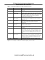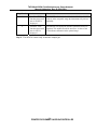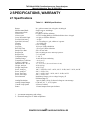
1
Teledyne API, Model 265A Chemiluminescence Ozone Analyzer Manual Addendum, 03389, Rev. B, DCN 5254 HIGHLIGHTS The purpose of this Highlights Page is to list the changes that were incorporated into this Manual per DCN 5254. Chapter / Page Number Description Changed Revision number and date. Title Page Changed address. Added DCN number to footer. Removed Revision letter referenced to instruction manual. Changed Revision number and date. Text – All Pages TOC / ii, iii Added DCN to all footers of Text, P/N 03389B. Added “PRINTED DOCUMENTS ARE UNCONTROLLED” to all footers of Manual, P/N 03389B. Updated List of Figures in TOC. 1/1 Removed Revision letter referenced to instruction manual. 2 / 12 Changed Revision number and date. Updated Warranty Section: Under Warranty, changed Revision Letter. Under General Section: removed first paragraph and replaced with “During the warranty period, T-API warrants each Product manufactured by T-API to be free from defects in material and workmanship under normal use and service. Expendable parts are excluded.” 2 / 13 Table 2-2, changed the BOX TEMP from 8-48°C to 8-40°C. Table 2-2, changed the PMT TEMP from 7±2°C to 8±2°C. PRINTED DOCUMENTS ARE UNCONTROLLED THIS PAGE IS INTENTIONALLY LEFT BLANK TELEDYNE INSTRUMENTS Advanced Pollution Instrumentation A Teledyne Technologies Company MANUAL ADDENDUM MODEL 265A CHEMILUMINESCENCE OZONE ANALYZER (ADDENDUM TO M200A INSTRUCTION MANUAL #02246) TELEDYNE INSTRUMENTS ADVANCED POLLUTION INSTRUMENTATION DIVISION 9480 CARROLL PARK DRIVE SAN DIEGO, CA 92121-2251 TOLL-FREE: FAX: TEL: E-MAIL: WEB SITE: Copyright 1999-2001 API Inc. 800-324-5190 858-657-9816 858-657-9800 [email protected] www.teledyne-api.com 03389 Rev B DCN 5254 15 December 2008 THIS PAGE IS INTENTIONALLY LEFT BLANK TAPI Model 265A Chemiluminescence Ozone Analyzer Manual Addendum, Rev. B, DCN 5254 SAFETY MESSAGES Your safety and the safety of others is very important. We have provided many important safety messages in this manual. Please read these messages carefully. A safety message alerts you to potential hazards that could hurt you or others. Each safety message is associated with a safety alert symbol. These symbols are found in the manual and inside the instrument. The definition of these symbols is described below: GENERAL WARNING/CAUTION: Refer to the instructions for details on the specific danger. CAUTION: Hot Surface Warning CAUTION: Electrical Shock Hazard Technician Symbol: All operations marked with this symbol are to be performed by qualified maintenance personnel only. Electrical Ground: This symbol inside the instrument marks the central safety grounding point for the instrument. CAUTION The analyzer should only be used for the purpose and in the manner described in this manual. If you use the analyzer in a manner other than that for which it was intended, unpredictable behavior could ensue with possible hazardous consequences. i PRINTED DOCUMENTS ARE UNCONTROLLED TAPI Model 265A Chemiluminescence Ozone Analyzer Manual Addendum, Rev. B, DCN 5254 TABLE OF CONTENTS SAFETY MESSAGES ....................................................................................................... I TABLE OF CONTENTS..................................................................................................II 1 GETTING STARTED ................................................................................................1 1.0 Overview ........................................................................................................................................... 1 1.1 Unpacking ......................................................................................................................................... 1 1.2 Electrical and Pneumatic Connections.............................................................................................. 2 1.3 Initial Operation ................................................................................................................................ 7 1.4 Instrument Calibration ...................................................................................................................... 7 2 SPECIFICATIONS, WARRANTY.............................................................................11 2.1 Specifications .................................................................................................................................. 11 2.2 Warranty.......................................................................................................................................... 12 2.3 Test and Calibration Values ............................................................................................................ 13 3 THE M265A OZONE ANALYZER........................................................................15 3.1 Principle of Operation ..................................................................................................................... 15 4 SOFTWARE FEATURES........................................................................................19 5 MAINTENANCE ..........................................................................................................23 5.1 Maintenance Schedule ................................................................................................................... 23 ii PRINTED DOCUMENTS ARE UNCONTROLLED TAPI Model 265A Chemiluminescence Ozone Analyzer Manual Addendum, Rev. B, DCN 5254 LIST OF FIGURES FIGURE 1-1: FIGURE 1-2: FIGURE 1-3: FIGURE 1-4: FIGURE 3-1: FIGURE 3-2: FIGURE 4-1: FIGURE 4-2: REMOVAL OF SHIPPING SCREWS & CHECK FOR CORRECT POWER ............ 3 M265A REAR PANEL .................................................................................................. 4 INLET AND EXHAUST VENTING RECOMMENDATIONS................................... 5 V/F BOARD SWITCH SETTINGS............................................................................... 6 BLOCK DIAGRAM .................................................................................................... 16 PNEUMATIC DIAGRAM........................................................................................... 17 SAMPLE MENU TREE .............................................................................................. 20 SETUP MENU TREE .................................................................................................. 21 LIST OF TABLES TABLE 2.1: M265A SPECIFICATIONS.......................................................................................... 11 TABLE 2-2: FINAL TEST AND CALIBRATION VALUES........................................................... 13 TABLE 5-1: PREVENTATIVE MAINTENANCE SCHEDULE ..................................................... 23 iii PRINTED DOCUMENTS ARE UNCONTROLLED TAPI Model 265A Chemiluminescence Ozone Analyzer Manual Addendum, Rev. B, DCN 5254 THIS PAGE IS INTENTIONALLY LEFT BLANK iv PRINTED DOCUMENTS ARE UNCONTROLLED TAPI Model 265A Chemiluminescence Ozone Analyzer Manual Addendum, Rev. B, DCN 5254 1 GETTING STARTED 1.0 Overview The Model 265A is a close derivative of the Model 200A Chemiluminescence NOx Analyzer. Because of this, the Model 200A Instruction manual continues to be valid as a reference manual covering the details of the instrument’s components, procedures, etc. This manual addendum is intended as supplement to the model 200A manual (Teledyne API part number 02246) and provides an overview of the instrument and the details of the features and functions that are specific to the 265A. 1.1 Unpacking CAUTION Your safety and the safety of others is very important. We have provided many important safety messages in this manual. Please read these messages carefully. To avoid personal injury, always use two persons to lift and carry the Model 265A. 1. Before operation it is necessary to remove the shipping hold-down screws. Remove the instrument cover, then remove three screws (painted red) as shown in Figure 1-1. Please remember if shipping or transporting the instrument to another site, the shipping screws must be re-installed to prevent damage to the sensor. 2. Also check for internal shipping damage, and generally inspect the interior of the instrument to make sure all circuit boards and other components are in good shape and properly seated. 3. Please check the voltage and frequency label on the serial number tag on the rear panel. Compare that to your local power before plugging the instrument into an outlet. 1 PRINTED DOCUMENTS ARE UNCONTROLLED TAPI Model 265A Chemiluminescence Ozone Analyzer Manual Addendum, Rev. B, DCN 5254 1.2 Electrical and Pneumatic Connections 1. See Figure 1-2 and Figure 1-3 to locate the rear panel electrical and pneumatic connections. 2. Attach the pump to the “Exhaust Out” port on the instrument rear panel. The exhaust from the pump should be vented to atmospheric pressure and out of the room, because of its NO content. 3. Attach the sample inlet line to the sample inlet port. The pressure of the sample gas at the inlet port should be at ambient pressure and constant. See Figure 1-3. 4. Attach a cylinder with 10,000 ppm ±10% of nitric oxide (NO) in nitrogen (N2), with an appropriate pressure regulator, to the 1/8” SS port on the rear panel as shown in Figure 1-2. The cylinder’s pressure regulator should be set to deliver gas at 20 PSIG ±10%. 5. Attach the analog output connections to a strip chart recorder and/or data-logger. See Figure 1-2 for connector pin-out definitions. See Figure 1-4 for V/F board switch settings. Factory default setting is 0-5 VDC. 6. Connect the power cord to the correct line voltage. WARNING Analyzer Exhaust Contains Nitric Oxide Gas. Vent pump exhaust to a well-ventilated area at atmospheric pressure. WARNING Lethal voltages present inside case. Do not operate with cover off during normal operation. Before operation, check for correct input voltage and frequency. Do not operate without proper chassis grounding. Do not defeat the ground wire on power plug. Turn off analyzer power before disconnecting electrical subassemblies. 2 PRINTED DOCUMENTS ARE UNCONTROLLED TAPI Model 265A Chemiluminescence Ozone Analyzer Manual Addendum, Rev. B, DCN 5254 Figure 1-1: Removal of Shipping Screws & Check for Correct Power 3 PRINTED DOCUMENTS ARE UNCONTROLLED TAPI Model 265A Chemiluminescence Ozone Analyzer Manual Addendum, Rev. B, DCN 5254 Figure 1-2: M265A Rear Panel 4 PRINTED DOCUMENTS ARE UNCONTROLLED TAPI Model 265A Chemiluminescence Ozone Analyzer Manual Addendum, Rev. B, DCN 5254 Figure 1-3: Inlet and Exhaust Venting Recommendations 5 PRINTED DOCUMENTS ARE UNCONTROLLED TAPI Model 265A Chemiluminescence Ozone Analyzer Manual Addendum, Rev. B, DCN 5254 Figure 1-4: V/F Board Switch Settings 6 PRINTED DOCUMENTS ARE UNCONTROLLED TAPI Model 265A Chemiluminescence Ozone Analyzer Manual Addendum, Rev. B, DCN 5254 1.3 Initial Operation 1. Turn on the instrument power. The display should immediately light, showing the computer’s memory configuration, then the instrument type - M265A. A diagram of the software menu trees can be found in Figure 4-1 and Figure 4-2. 2. On power-up, an internal solenoid valve will open allowing NO to flow. Check the NO FLOW test function on the front panel to verify that the flow is 5 cm³/min ±20%. If the flow is out of this range, check the inlet pressure at the rear panel and make sure that it is 20 psi, then adjust the pressure regulator on the rear panel until the flow is within range. 3. The M265A requires about 30 minutes for all internal components to heat to operating temperature. Many warning conditions are not displayed during this time, even though some parameters are out of specification. All warning messages are enabled after 30 minutes of operation. 4. When the instrument is warmed up, check the TEST functions. All of the readings should compare closely with those in Table 2-2. 5. Next is instrument calibration, which is shown in the following tables. 1.4 Instrument Calibration Step 1 - Set the range, then enter the expected ozone span gas concentrations: Step Number Action Comment 1. Press CAL-CONC This key sequence causes the M265A to prompt for the expected span concentration. Enter the span value by pressing the key under each digit until the expected value is set. 2. Press ENTR ENTR stores the expected span value. The internal formula is adjusted to compute this number when span gas concentration is input into the instrument. 5. Press EXIT Returns instrument to SAMPLE mode. 6. Press SETUP-RNGEMODE-SNGL If necessary, you may want to change the range mode. Choices are either Single or AutoRange. Normally the instrument is shipped in Single range mode. 7. Press SETUP-RNGESET After the mode is set, you may want to set the maximum range value. The instrument is shipped with the range set at 500 ppb. This setting affects only your analog outputs, not the RS-232 output. 7 PRINTED DOCUMENTS ARE UNCONTROLLED TAPI Model 265A Chemiluminescence Ozone Analyzer Manual Addendum, Rev. B, DCN 5254 Step 2 - Calibrate the instrument: Zero/Span Calibration Procedure Step Number Action Comment 1. Input zero gas Allow zero gas to enter the sample port on the rear of the instrument. 2. Press CAL The M265A enters the calibrate mode from sample mode. 3. Wait 10 min Wait for reading to stabilize at the zero value. If you wait less than 10 minutes the final zero value may drift. You may want to watch the STABIL test function (moving standard deviation) for its minimum value. 4. Press ZERO The ZERO button will be displayed once the concentration approaches zero. 5. Press ENTR Pressing ENTR zeroes the instrument and actually changes both offset and slope of the equations to calculate concentration. 6. Press EXIT, input Span gas M265A returns to the CAL menu. Now allow span gas to flow through the instrument. 7. Wait 10 min Wait for the O3 reading to stabilize at the span value (watch STABIL). 8. Press SPAN The SPAN button should be displayed once the concentration approaches the span value. In certain circumstances at low span gas concentrations both the ZERO and SPAN buttons will appear. Do not press ZERO again when running span gas! 9. Press ENTR Pressing ENTR to span the instrument actually changes the equations so that the concentration displayed is the same as the expected span concentration you entered above, thus spanning the instrument. 10. Press EXIT Pressing EXIT returns the instrument to SAMPLE mode. Step 3 - Review Quality of calibration: Calibration Quality Check Procedure 8 PRINTED DOCUMENTS ARE UNCONTROLLED TAPI Model 265A Chemiluminescence Ozone Analyzer Manual Addendum, Rev. B, DCN 5254 Step Number Action Comment 1. Scroll the TEST function menu until the O3 SLOPE is displayed. The SLOPE value for O3 should be 1.0 ± 0.3. If the SLOPE value is in the acceptable range the instrument will perform optimally. 2. Scroll the TEST function menu until the O3 OFFS is displayed. The M265A will display the OFFSET parameter for the O3 equation. This number should be near zero. A value of 0.0 ±50 indicates calibration in the optimal range. Step 4 - The M265A is now ready to measure sample gas. 9 PRINTED DOCUMENTS ARE UNCONTROLLED TAPI Model 265A Chemiluminescence Ozone Analyzer Manual Addendum, Rev. B, DCN 5254 THIS PAGE IS INTENTIONALLY LEFT BLANK 10 PRINTED DOCUMENTS ARE UNCONTROLLED TAPI Model 265A Chemiluminescence Ozone Analyzer Manual Addendum, Rev. B, DCN 5254 2 SPECIFICATIONS, WARRANTY 2.1 Specifications Table 2.1: M265A Specifications Ranges Measurement Mode Measurement Units Noise at zero Noise at span Lower Detectable Limit Zero Drift (24 hours)1 Span Drift (24 hours)1 Linearity Precision Lag Time Rise/Fall Time Sample Flow Rate Reagent Gas Reagent Flow Temperature Range Humidity Range Temperature Coefficient Voltage Coefficient Dimensions H x W x D Weight, Analyzer Weight, Pump Pack Power, Analyzer Power, Analyzer2 Power, Ext Pump Power, Ext Pump2 Environmental2 Analog Resolution Analog Output Ranges Current Loop Option Status In 1 ppb increments from 100 ppb to 20,000 ppb Single range or AutoRange ppb, µg/m3 0.3 ppb per USEPA definition <0.5% of reading RMS per USEPA definition above 100 ppb <0.6 ppb per USEPA definition <1.0 ppb <1% of reading or 1 ppb, whichever is greater <1% of full scale 0.5% of reading 10 sec per USEPA definition <20 sec per USEPA definition 500 ± 50 cm³/min NO at 10,000 ppm ±10% and 20 psi pressure 5 ± 1 cm³/min 5 – 40° C 10-90% RH non-condensing < 0.1% per °C < 0.1% per V 7" x 17" x 23.6" (18 cm x 43 cm x 61 cm) 36 lbs (16 kg) 16 lbs (7 kg) 100 V~ 50/60 Hz, 120 V~ 60 Hz, 220 V~ 50 Hz, 240 V~ 50 Hz, 200 W 230 V~ 50 Hz, 2.5A 110 V~ 60 Hz, 220 V~ 50 Hz, 240 V~ 50 Hz, 295 W 230 V~ 50 Hz, 2.5A Installation Category (Over-voltage Category) II Pollution Degree 2 1 part in 2048 (11 bit) of selected voltage or current range 0-100 mV, 0-1, 5, 10 V, bipolar 4-20 mA, isolated 12 status outputs from opto-isolators 1. At constant temperature and voltage. 2. Electrical ratings for CE Mark compliance. 11 PRINTED DOCUMENTS ARE UNCONTROLLED TAPI Model 265A Chemiluminescence Ozone Analyzer Manual Addendum, Rev. B, DCN 5254 2.2 Warranty ADVANCED POLLUTION INSTRUMENTATION DIVISION (T-API) (02024D) (DCN 4473) Prior to shipment, Teledyne API equipment is thoroughly inspected and tested. Should equipment failure occur, Teledyne API assures its customers that prompt service and support will be available. COVERAGE After the warranty period and throughout the equipment lifetime, Teledyne API stands ready to provide on-site or in-plant service at reasonable rates similar to those of other manufacturers in the industry. All maintenance and the first level of field troubleshooting is to be performed by the customer. NON-API MANUFACTURED EQUIPMENT Equipment provided but not manufactured by Teledyne API is warranted and will be repaired to the extent and according to the current terms and conditions of the respective equipment manufacturers warranty. GENERAL During the warranty period, T-API warrants each Product manufactured by T-API to be free from defects in material and workmanship under normal use and service. Expendable parts are excluded. If a product fails to conform to its specifications within the warranty period, Teledyne API shall correct such defect by, in Teledyne API's discretion, repairing or replacing such defective product or refunding the purchase price of such product. The warranties set forth in this section shall be of no force or effect with respect to any product: (i) that has been altered or subjected to misuse, negligence or accident, or (ii) that has been used in any manner other than in accordance with the instruction provided by API or (iii) not properly maintained. THE WARRANTIES SET FORTH IN THIS SECTION AND THE REMEDIES THEREFORE ARE EXCLUSIVE AND IN LIEU OF ANY IMPLIED WARRANTIES OF MERCHANTABILITY, FITNESS FOR PARTICULAR PURPOSE OR OTHER WARRANTY OF QUALITY, WHETHER EXPRESSED OR IMPLIED. THE REMEDIES SET FORTH IN THIS SECTION ARE THE EXCLUSIVE REMEDIES FOR BREACH OF ANY WARRANTY CONTAINED HEREIN. TELEDYNE API SHALL NOT BE LIABLE FOR ANY INCIDENTAL OR CONSEQUENTIAL DAMAGES ARISING OUT OF OR RELATED TO THIS AGREEMENT OF TELEDYNE API'S PERFORMANCE HEREUNDER, WHETHER FOR BREACH OF WARRANTY OR OTHERWISE. TERMS AND CONDITIONS All units or components returned to Teledyne API should be properly packed for handling and returned freight prepaid to the nearest designated service center. After the repair, the equipment will be returned, freight prepaid. 12 PRINTED DOCUMENTS ARE UNCONTROLLED TAPI Model 265A Chemiluminescence Ozone Analyzer Manual Addendum, Rev. B, DCN 5254 2.3 Test and Calibration Values Table 2-2: Final Test and Calibration Values TEST Values Observed Value Units Nominal Range RANGE ppb 10-20000 NOISE ppb 0.0 – 7.0 SAMP FLW cm³/min 500 ± 50 NO FLOW cm³/min 5±1 PMT mV 0-5000 AUTOZERO mV -10 to +50 HVPS V 400 – 850 constant DCPS mV 2500 ± 200 RCELL TEMP °C 50 ± 2 BOX TEMP °C 8-40 PMT TEMP °C 8±2 RCEL PRES IN-Hg-A 2 - 10 constant SAMP PRES IN-Hg-A 20 - 30 constant NO PRES PSIG 3 - 20 constant Electric Test &Optic Test Electric Test PMT Volts mV 2000 ± 200 O3 Conc ppb 1000 ± 100 OPTIC TEST PMT Volts mV 2000 ± 200 O3 Conc ppb 1000 ± 100 (table continued) 13 PRINTED DOCUMENTS ARE UNCONTROLLED Reference Section TAPI Model 265A Chemiluminescence Ozone Analyzer Manual Addendum, Rev. B, DCN 5254 Table 2-2: Final Test and Calibration Values (Continued) Parameter Observed Value O3 Span Conc Units Nominal Range ppb 0.5 - 5000 O3 Slope 1.0 ± 0.3 O3 Offset mV ± 25 Noise at Zero ppb 0.0 – 1.0 Noise At Span ppb 0.1 – 7.0 Measured Flows Sample Flow cm³/min Factory Installed Options 500 ± 50 Option Installed Power Voltage/Frequency PROM # Serial # Date Technician 14 PRINTED DOCUMENTS ARE UNCONTROLLED Reference Section TAPI Model 265A Chemiluminescence Ozone Analyzer Manual Addendum, Rev. B, DCN 5254 3 THE M265A OZONE ANALYZER 3.1 Principle of Operation The Teledyne API Model 265A analyzer is designed to measure the concentration of ozone using the chemiluminescence reaction below. The signal comes from the light emitted by the gas phase reaction of nitric oxide (NO) and ozone (O3) as follows: NO O3 NO2* O2 NO2* NO2 hv The reaction of ozone with NO results in electronically excited NO2* molecules as shown in the first equation. The excited NO2* molecules release their excess energy by emitting a photon hν and dropping to a lower energy level as shown in the second equation. It has been shown that the number of emitted photons is directly proportional to the O3 concentration in the reaction cell. Periodically, an AutoZero valve switches the sample stream to vacuum, allowing the reaction cell to be evacuated and the analyzer to read zero background. The AutoZero readings are subtracted from the concentration readings, which improves zero baseline stability. 15 PRINTED DOCUMENTS ARE UNCONTROLLED TAPI Model 265A Chemiluminescence Ozone Analyzer Manual Addendum, Rev. B, DCN 5254 Figure 3-1: Block Diagram 16 PRINTED DOCUMENTS ARE UNCONTROLLED TAPI Model 265A Chemiluminescence Ozone Analyzer Manual Addendum, Rev. B, DCN 5254 Figure 3-2: Pneumatic Diagram 17 PRINTED DOCUMENTS ARE UNCONTROLLED TAPI Model 265A Chemiluminescence Ozone Analyzer Manual Addendum, Rev. B, DCN 5254 THIS PAGE IS INTENTIONALLY LEFT BLANK 18 PRINTED DOCUMENTS ARE UNCONTROLLED TAPI Model 265A Chemiluminescence Ozone Analyzer Manual Addendum, Rev. B, DCN 5254 4 SOFTWARE FEATURES The M265A software has two major operating modes. The SAMPLE mode is the normal mode when the instrument is taking data. The software menu that covers the SAMPLE mode is shown in Figure 4-1. When the instrument is initially installed, a change of parameters is needed, or diagnostics is indicated, the SETUP menu is used, which is shown in Figure 4-2. 19 PRINTED DOCUMENTS ARE UNCONTROLLED TAPI Model 265A Chemiluminescence Ozone Analyzer Manual Addendum, Rev. B, DCN 5254 Figure 4-1: Sample Menu Tree 20 PRINTED DOCUMENTS ARE UNCONTROLLED TAPI Model 265A Chemiluminescence Ozone Analyzer Manual Addendum, Rev. B, DCN 5254 Figure 4-2: Setup Menu Tree 21 PRINTED DOCUMENTS ARE UNCONTROLLED TAPI Model 265A Chemiluminescence Ozone Analyzer Manual Addendum, Rev. B, DCN 5254 THIS PAGE IS INTENTIONALLY LEFT BLANK 22 PRINTED DOCUMENTS ARE UNCONTROLLED TAPI Model 265A Chemiluminescence Ozone Analyzer Manual Addendum, Rev. B, DCN 5254 5 MAINTENANCE 5.1 Maintenance Schedule NOTE The operations outlined in this chapter are to be performed by qualified maintenance personnel only. Table 5-1: Preventative Maintenance Schedule Item Maintenance Interval Reference Section TEST functions Review monthly See M200A manual, Table 8-1 Zero/Span calibration Annually or after repairs See M200A manual, Table 8-1 Zero/Span checks Daily See M200A manual, Table 8-1 Particulate filter Weekly as needed See M200A manual, Table 8-1 Reaction cell window Clean annually or as necessary See M200A manual, Table 8-1 Nitric oxide flow Check TEST function every month Section 1-3 See also M200A manual, Table 8-1 (O3 flows) Sample Flow Check TEST function every month See M200A manual, Table 8-1 Pneumatic lines Examine every 12 months, clean if necessary. See M200A manual, Table 8-1 Factory calibration Calibrate each year or after repairs See M200A manual, Table 8-1 Leak Check Check every year or after other maintenance. See M200A manual, Table 8-1 Reaction cell O-rings Replace every 12 months See M200A manual, Table 8-1 Other O-rings Replace every 12 months See M200A manual, Table 8-1 23 PRINTED DOCUMENTS ARE UNCONTROLLED TAPI Model 265A Chemiluminescence Ozone Analyzer Manual Addendum, Rev. B, DCN 5254 THIS PAGE IS INTENTIONALLY LEFT BLANK 24 PRINTED DOCUMENTS ARE UNCONTROLLED