1
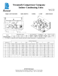
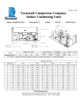
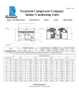
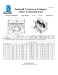
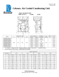
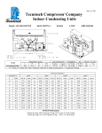
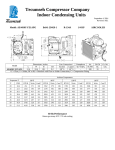
October 28, 2013 Revision: REL Tecumseh Compressor Company Indoor Condensing Units Model: AJA7510ZXDXC BoM: 2B1181-1 R-404A 1 1/4 HP AIRCOOLED Dimensions, inches Line Connection* Pumpdown Air L W H CH Suction Liquid 90 F 90% SCFM 18.0 35.0 12.6 12.4 5/8” S 3/8” S 7.30 lbs 800 AJA7510ZXDXC * F = Flare, S = Solder, RF or RS = Rotolock with Flare or Solder Connections, C = Compression Fitting Model Oil Ch Oz. 26.5 Gr. Wt. Lbs. --- Ambient Temperatures Evaporator T 80F 90F 100F 110F °F PSIG BTUH Watts Cond T BTUH Watts Cond T BTUH Watts Cond T BTUH Watts Cond T -10 23.2 6188 1329 96 5458 1338 105 4577 1307 114 3898 1299 122 -5 28.1 6937 1418 98 6145 1433 107 5301 1415 115 4509 1400 124 0 32.8 7740 1512 100 6882 1534 109 6052 1527 117 5152 1511 125 5 37.9 8598 1610 102 7669 1640 111 6831 1644 119 5827 1630 127 10 43.3 9510 1713 105 8505 1751 113 7637 1764 121 6533 1758 130 15 49.1 10476 1821 107 9392 1867 116 8471 1889 123 7271 1896 132 20 55.5 11498 1934 109 10328 1988 118 9331 2019 125 8040 2043 134 25 62.2 12573 2051 112 11314 2114 121 10219 2152 128 8840 2199 136 30 69.5 13703 2172 115 12350 2245 123 11135 2290 131 9672 2364 138 60 Hz Performance Return gas temp. 40F Evaporator Temp. 20F or less, 5F sub-cooling Return gas temp. 65F for Evaporator Temp. > 20F, 5F sub-cooling October 28, 2013 Revision: REL Specifications/ Parts: Model Unit Bill of Material Nominal Volts-Hz-Ph Refrigeration Range Design Pressure Low Design Pressure High Voltage Range Min. Circuit Ampacity Max. Fuse Size (amps) Compressor Model Comp. Bill of Material Compressor RLA/LRA Overload Relay Run Capacitor Run Capacitor Rating Start Capacitor Start Capacitor Rating Contactor Unit Drawing Wiring Diagram AJA7510ZXDXC 2B1181-1 208-230-60-1 -10° to 30°F 181 450 187 to 254 11.9 20 AJA7494ZXD AJ202ET-188-P21 9.2 / 54 INTERNAL 8200RVAM25 85PR370F20 25MFD 370V(M) VDE 85PS250B87 216-259 MFD 250V VDE N/A DGU1893-90 91267-01 Fan Motor Fan Motor RLA Fan Blade Fan Guard Fan Shroud Dual Pressure Control Condenser Receiver Tank with Valve Liquid Filter Sight Glass Suction Valve Rotolock Valve Gasket Discharge Valve Suction Filter * Accumulator * Crankcase Heater Defrost Timer * * = Equipped Units Only Electrical Diagram 810-10079 (2) 0.2 Each 515-10004 (2) 570-10000 (2) 707-10000 14955206 506-10005 510-10003 70081 70084 31590 30234 56630-A N/A N/A N/A N/A