1
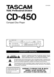
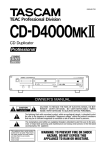
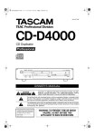
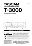
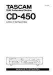
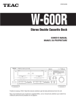
»
IF-AE8
D00446000A
Digital Audio Interface Unit
OWNER’S MANUAL
Ü
ÿ
Ÿ
CAUTION: TO REDUCE THE RISK OF ELECTRIC SHOCK, DO NOT
REMOVE COVER (OR BACK). NO USER-SERVICEABLE PARTS
INSIDE. REFER SERVICING TO QUALIFIED SERVICE PERSONNEL.
The lightning flash with arrowhead symbol, within an equilateral triangle, is intended to alert
the user to the presence of uninsulated “dangerous voltage” within the product’s enclosure
that may be of sufficient magnitude to constitute a risk of electric shock to persons..
The exclamation point within an equilateral triangle is intended to alert the user to the presence of important operating and maintenance (servicing) instructions in the literature
accompanying the appliance.
This appliance has a serial number
located on the rear panel. Please record
the model number and serial number
and retain them for your records.
Model number
Serial number
WARNING: TO PREVENT FIRE OR SHOCK
HAZARD, DO NOT EXPOSE THIS
APPLIANCE TO RAIN OR MOISTURE.
Important Safety Precautions
IMPORTANT (for U.K. Customers)
For U.S.A
TO THE USER
DO NOT cut off the mains plug from this equipment.
If the plug fitted is not suitable for the power points in your
home or the cable is too short to reach a power point, then
obtain an appropriate safety approved extension lead or
consult your dealer.
If nonetheless the mains plug is cut off, remove the fuse and
dispose of the plug immediately, to avoid a possible shock
hazard by inadvertent connection to the mains supply.
If this product is not provided with a mains plug, or one has
to be fitted, then follow the instructions given below:
IMPORTANT. DO NOT make any connection to the larger
terminal which is marked with the letter E or by the safety
earth symbol ç or coloured GREEN or GREEN-andYELLOW.
The wires in the mains lead on this product are coloured in
accordance with the following code:
BLUE:
BROWN:
NEUTRAL
LIVE
This equipment has been tested and found to
comply with the limits for a Class A digital device,
pursuant to Part 15 of the FCC Rules. These
limits are designed to provide reasonable
protection against harmful interference when the
equipment is operated in a commercial
environment. This equipment generates, uses,
and can radiate radio frequency energy and, if
not installed and used in accordance with the
instruction manual, may cause harmful
interference to radio communications.
Operation of this equipment in a residental area
is likely to cause harmful interference in which
case the user will be required to correct the
interference at his own expense.
CAUTION
Changes or modifications to this equipment not
expressly approved by TEAC CORPORATION
for compliance could void the user’s authority to
operate this equipment.
As these colours may not correspond with the coloured
markings identifying the terminals in your plug proceed as
follows:
For the consumers in Europe
The wire which is coloured BLUE must be connected to the
terminal which is marked with the letter N or coloured
BLACK.
WARNING
This is a Class A product. In a domestic environment, this
product may cause radio interference in which case the user
may be required to take adequate measures.
The wire which is coloured BROWN must be connected to
the terminal which is marked with the letter L or coloured
RED.
When replacing the fuse only a correctly rated approved
type should be used and be sure to re-fit the fuse cover.
IF IN DOUBT — CONSULT A COMPETENT
ELECTRICIAN.
Pour les utilisateurs en Europe
AVERTISSEMENT
Il s’agit d’un produit de Classe A. Dans un environnement
domestique, cet appareil peut provoquer des interférences
radio, dans ce cas l’utilisateur peut être amené à prendre
des mesures appropriées.
Für Kunden in Europa
Warnung
Dies is eine Einrichtung, welche die Funk-Entstörung nach
Klasse A besitzt. Diese Einrichtung kann im Wohnbereich
Funkstörungen versursachen ; in diesem Fall kann vom
Betrieber verlang werden, angemessene Maßnahmen
durchzuführen und dafür aufzukommen.
2
TASCAM IF-AE8
IMPORTANT SAFETY INSTRUCTIONS
CAUTION:
… Read all of these Instructions.
… Save these Instructions for later use.
… Follow all Warnings and Instructions marked on the audio
equipment.
1) Read Instructions — All the safety and operating instructions should
be read before the product is operated.
2) Retain Instructions — The safety and operating instructions should
be retained for future reference.
3) Heed Warnings — All warnings on the product and in the operating
instructions should be adhered to.
4) Follow Instructions — All operating and use instructions should be
followed.
5) Cleaning — Unplug this product from the wall outlet before cleaning.
Do not use liquid cleaners or aerosol cleaners. Use a damp cloth for cleaning.
6) Attachments — Do not use attachments not recommended by the
product manufacturer as they may cause hazards.
7) Water and Moisture — Do not use this product near water — for
example, near a bath tub, wash bowl, kitchen sink, or laundry tub; in a wet
basement; or near a swimming pool; and the like.
8) Accessories — Do not place this product on an unstable cart, stand,
tripod, bracket, or table. The product may fall, causing serious injury to a
child or adult, and serious damage to the product. Use only with a cart,
stand, tripod, bracket, or table recommended by the manufacturer, or sold
with the product. Any mounting of the product should follow the manufacturer’s instructions, and should use a mounting accessory recommended by
the manufacturer.
9) A product and cart combination should be moved with care. Quick stops,
excessive force, and uneven surfaces may cause the product and cart combination to overturn.
10) Ventilation — Slots and openings in the cabinet are provided for ventilation and to ensure reliable operation of the product and to protect it
from overheating, and these openings must not be blocked or covered. The
openings should never be blocked by placing the product on a bed, sofa,
rug, or other similar surface. This product should not be placed in a built-in
installation such as a bookcase or rack unless proper ventilation is provided
or the manufacturer’s instructions have been adhered to.
11) Power Sources — This product should be operated only from the
type of power source indicated on the marking label. If you are not sure of
the type of power supply to your home, consult your product dealer or local
power company. For products intended to operate from battery power, or
other sources, refer to the operating instructions.
12) Grounding or Polarization — This product may be equipped with a
polarized alternating-current line plug (a plug having one blade wider than
the other). This plug will fit into the power outlet only one way. This is a
safety feature. If you are unable to insert the plug fully into the outlet, try
reversing the plug. If the plug should still fail to fit, contact your electrician
to replace your obsolete outlet. Do not defeat the safety purpose of the
polarized plug.
13) Power-Cord Protection — Power-supply cords should be routed so
that they are not likely to be walked on or pinched by items placed upon or
against them, paying particular attention to cords at plugs, convenience
receptacles, and the point where they exit from the product.
14) Outdoor Antenna Grounding — If an outside antenna or cable
system is connected to the product, be sure the antenna or cable system is
grounded so as to provide some protection against voltage surges and builtup static charges. Article 810 of the National Electrical Code, ANSI/NFPA
70, provides information with regard to proper grounding of the mast and
supporting structure, grounding of the lead-in wire to an antenna discharge
unit, size of grounding conductors, location of antenna-discharge unit, connection to grounding electrodes, and requirements for the grounding electrode.
"Note to CATV system installer:
This reminder is provided to call the CATV system installer’s attention to
Section 820-40 of the NEC which provides guidelines for proper grounding
and, in particular, specifies that the cable ground shall be connected to the
grounding system of the building, as close to the point of cable entry as
practical.
Example of Antenna Grounding as per
National Electrical Code, ANSI/NFPA 70
ANTENNA
LEAD IN
WIRE
GROUND
CLAMP
ANTENNA
DISCHARGE UNIT
(NEC SECTION 810-20)
ELECTRIC
SERVICE
EQUIPMENT
GROUNDING CONDUCTORS
(NEC SECTION 810-21)
GROUND CLAMPS
POWER SERVICE GROUNDING
ELECTRODE SYSTEM
(NEC ART 250. PART H)
NEC - NATIONAL ELECTRICAL CODE
15) Lightning — For added protection for this product during a lightning
storm, or when it is left unattended and unused for long periods of time,
unplug it from the wall outlet and disconnect the antenna or cable system.
This will prevent damage to the product due to lightning and power-line
surges.
16) Power Lines — An outside antenna system should not be located in
the vicinity of overhead power lines or other electric light or power circuits,
or where it can fall into such power lines or circuits. When installing an
outside antenna system, extreme care should be taken to keep from touching such power lines or circuits as contact with them might be fatal.
17) Overloading — Do not overload wall outlets, extension cords, or
integral convenience receptacles as this can result in risk of fire or electric
shock.
18) Object and Liquid Entry — Never push objects of any kind into
this product through openings as they may touch dangerous voltage points
or short-out parts that could result in a fire or electric shock. Never spill
liquid of any kind on the product.
19) Servicing — Do not attempt to service this product yourself as opening or removing covers may expose you to dangerous voltage or other
hazards. Refer all servicing to qualified service personnel.
20) Damage Requiring Service — Unplug this product from the wall
outlet and refer servicing to qualified service personnel under the following
conditions:
a) when the power-supply cord or plug is damaged.
b) if liquid has been spilled, or objects have fallen into the product.
c) if the product has been exposed to rain or water.
d) if the product does not operate normally by following the operating
instructions. Adjust only those controls that are covered by the operating
instructions as an improper adjustment of other controls may result in
damage and will often require extensive work by a qualified technician to
restore the product to its normal operation.
e) if the product has been dropped or damaged in any way.
f ) when the product exhibits a distinct change in performance – this
indicates a need for service.
21) Replacement Parts — When replacement parts are required, be
sure the service technician has used replacement parts specified by the
manufacturer or have the same characteristics as the original part.
Unauthorized substitutions may result in fire, electric shock, or other
hazards.
22) Safety Check — Upon completion of any service or repairs to this
product, ask the service technician to perform safety checks to determine
that the product is in proper operating condition.
23) Wall or Ceiling Mounting — The product should be mounted to a
wall or ceiling only as recommended by the manufacturer.
24) Heat — The product should be situated away from heat sources such
as radiators, heat registers, stoves, or other products (including amplifiers)
that produce heat.
TASCAM IF-AE8 3
IF-AE8 Digital Audio Converter
The TASCAM IF-AE8 provides a convenient way of
exchanging digital audio data between
TDIF-1-equipped devices, such as DTRS recorders,
and AES/EBU devices.
If sampling frequency conversion is carried out, the
IF-AE8 will generate an independent clock signal,
based on the target frequency, so that other units may
be synchronized to it.
A single TDIF-1 connector carries eight channels of
digital input and output. Four XLR-type connectors
accept four two-channel input signals in AES3-1992
format, and another four XLR-type connectors output four two-channel input signals in AES3-1992
format.
The signal transmitted from the AES/EBU outputs
can be selected to come from the AES/EBU input
signals or from those received at the TDIF-1 connector, using a front panel switch.
The word synchronization is selectable, using a front
panel switch, from any of the four AES/EBU inputs,
from the TDIF-1 source, or from an external independent word clock source.
The word clock source can be used as the clock
source for sampling frequency conversion. All standard rates (32 kHz, 44.1 kHz and 48 kHz) are supported for input and output.
1 POWER switch and indicator
Push the POWER switch once to turn on power, and
again to turn it off. The POWER indicator lights
when power is supplied to the IF-AE8.
2 LOCKED indicator
When a valid clock signal is received at the selected
clock source, this indicator will light.
3 CLOCK switch and indicators
This switch allows you to cycle between the six possible clock sources for the IF-AE8: the WORD
SYNC IN A connector, the DIGITAL I/O (TDIF-1)
9 connector, or any of the four two-channel
AES/EBU connectors (DIGITAL I/O (AES/EBU)
INPUTS (1/2, 3/4, 5/6, 7/8) 8), as shown by the
indicators to the right of the switch.
WARNING
There should usually never be more than one
word clock signal in a digital audio system. If
there are not, at worst, damage may occur to
speakers, amplifiers, etc. as a result of
4
TASCAM IF-AE8
Format conversion is possible with up to 24-bit data
with TDIF digital audio format, and 20-bit with
AES3-1992 format data if no sample rate conversion
is performed (20-bit data for both formats if the sampling frequency is converted).
The digital audio output format is selectable as either
professional or consumer format using a front panel
switch.
1
Front panel
high-frequency noise generated by word clock
incompatibilities.
4 DIGITAL OUT switch and indicators
This switch allows you to select the source of the
digital audio signals that are output from the
DIGITAL I/O (AES/EBU) OUTPUTS (1/2, 3/4,
5/6, 7/8) 7. The source can either be the signals
received at the AES/EBU inputs 8 (DIGITAL IN)
or at the TDIF-1 connector 9.
If the TDIF-1 option is selected, the eight channels of
the TDIF-1 audio are mapped on a “one-to-one”
basis to the eight AES/EBU audio output channels.
If the DIGITAL IN option is selected, the input data
received at the AES/EBU ports is passed through to
the corresponding output ports. However, it may be
passed through the sample rate conversion before
reaching the output ports.
5 DIGITAL OUT FORMAT switch and
indicators
The format of the digital audio output from the
AES/EBU output connectors 7 may be either professional AES3-1992 format (PRO) or
IF-AE8 Digital Audio Converter
CONSUMER IEC-60958 TYPE II format. The electrical characteristics of the output connectors remain
the same, regardless of the data format selected.
6 Fs RATE CONVERT switch and
indicators
the clock source for the converted signal. The
DIGITAL I/O (TDIF-1) 9 cannot be used as the
clock source for conversion, though both it and the
DIGITAL I/O (AES/EBU) OUTPUTS (1/2, 3/4,
5/6, 7/8) 7 can be the destination.
This switch provides two settings: THRU-1 and
CONVERT.
When the switch is set to THRU-1, the input signals
(selected using the DIGITAL OUT 4 switch) will be
output from the AES/EBU output connectors at the
same frequency.
NOTE
The AES/EBU unit which provides this clock
source may be different from the unit which
provides either the input or the output signals.
You must, however, make sure that word
clock synchronization is correctly carried out.
When the switch is set to CONVERT, the input signals will be output at the sampling frequency of the
clock source selected with the CLOCK switch 3.
Note that any of the DIGITAL I/O (AES/EBU)
INPUTS (1/2, 3/4, 5/6, 7/8) 8 may be selected as
2
7 DIGITAL I/O (AES/EBU) OUTPUTS
(1/2, 3/4, 5/6, 7/8)
The signals received at this connector may be
selected as the word clock source using the CLOCK
switch 3.
These balanced connectors output digital audio data
in AES3-1992 professional or in consumer format,
depending on the selection made with the DIGITAL
OUT FORMAT switch 5.
The content of the data depends on the setting of the
DIGITAL OUT switch 4.
The sampling frequency of the output data depends
on the setting of the Fs RATE CONVERT switch
6, and the currently-selected clock source 3.
8 DIGITAL I/O (AES/EBU) INPUTS (1/2,
3/4, 5/6, 7/8)
These balanced connectors accept digital audio data
in AES3-1992 format.
The signal received at any of these connectors may
be selected as the clock source for the IF-AE8 using
the CLOCK switch 3
9 DIGITAL I/O (TDIF-1)
Use this connector to connect a suitably-equipped
TDIF-1 digital audio unit (e.g. a DTRS recorder or a
TASCAM digital mixing console).
Rear panel
WARNING
Note that you should always use genuine
TASCAM cables, or cables which have been
approved for use with TDIF-1 interfaces by
TASCAM.
Although these cables appear similar to certain types of computer cables and use similar
connectors, the cables themselves are very
different, and the different electrical characteristics of the cables can cause damage to the
equipment connected with the wrong cables.
If the use of cables other than TASCAM
cables causes or results in damage, the warranty is voided.
A WORD SYNC IN
The BNC connector accepts a word clock signal
from an external source.
It may be selected as the word clock source for the
IF-AE8 using the CLOCK switch 3.
TASCAM IF-AE8 5
IF-AE8 Digital Audio Converter
B WORD SYNC OUT
This BNC connector outputs a word clock based on
the word clock source selected using the CLOCK
switch 3.
NOTE
This may or may not be the same as the clock
received at WORD SYNC IN A and retransmitted through WORD SYNC THRU C. However, it is always the word clock selected
using the CLOCK switch 3.
C WORD SYNC THRU
This BNC connector echoes the word clock signal
received at WORD SYNC IN A. It may or may not
be the same signal as is output at WORD SYNC
OUT B. It is auto-terminating.
3
Application example
In this example, the original material (from two
sources) has been mixed to DAT, and has been produced in both professional and consumer formats,
and at both 44.1 kHz and 48 kHz sample rates.
The final master data will be recorded and coded on a
computer-based system, with an AES/EBU interface.
DAT 1
AES/EBU audio in
48 (C)
DAT 2
44.1 (P)*
The mastering system takes its word clock through
the AES/EBU data from the appropriate DIGITAL
OUT of the IF-AE8.
The DIGITAL OUT FORMAT switch 5 is set to
PRO, so that the data coming from DAT 2 is converted to professional format data.
4
Specifications
DIGITAL OUTPUTs (1–2,
3–4, 5–6, 7–8)
XLR-type, balanced outputs
DIGITAL OUTPUT output
format
Switchable between
professional (AES3-1992)
and consumer (IEC-60958
TYPE II) formats
DIGITAL INPUTS (1–2, 3–4,
5–6, 7–8)
XLR-type
DIGITAL INPUT input format
Auto-detect professional
(AES3-1992) and consumer
(IEC-60958 TYPE II) formats
D IGITAL I/O (TDIF-1)
Conforms to TDIF-1
specification
Clock source
Any of AES/EBU DIGITAL
INPUTS, TDIF-1, or WORD
SYNC IN (front panel
selection)
LOCKED indicator
Lights when valid clock
source received at selected
input
Valid input Fs rates
48 kHz, 44.1 kHz, 32 kHz
Valid output rates
48 kHz, 44.1 kHz, 32 kHz,
taken from CLOCK source
Word length
Up to 24 bits TDIF-1,(20 bits
with Fs conversion), 20 bits
AES3-1992
WORD SYNC IN
75Ω
WORD SYNC OUT
75Ω, reproduces clock
selected from front panel
switch
WORD SYNC THRU
75Ω (auto terminating),
echoes clock at WORD
SYNC IN
Dimensions (w x h x d)
428 x 48 x 194.8 (mm)
16.9 x 1.9 x 7.7 (in.)
Weight
2.6 kg (5.7 lbs)
Power supply
120V (UL), 230V (Europe,
Australia)
Power consumption
6W
Supplied accessories
Rack mounting kit
IF-AE8
44.1(P)
Mastering
system
Here, the two DAT recorders are fed through the
IF-AE8. Since the resulting data will be at 44.1 kHz,
the DAT playing back the material at 44.1 kHz
(DAT 1) is selected to act as the clock master.
Since the TDIF-1 I/O is not used here, the DIGITAL
OUT switch 4 is set to DIGITAL IN.
The word clock is therefore derived from this, and
used to resample the 48 kHz material from DAT 2,
and the Fs RATE CONVERT switch 6 is set to
CONVERT.
6
TASCAM IF-AE8
IF-AE8 Digital Audio Converter
4.1 Dimensional drawing
4.2 Rack mounting
Use the supplied rack mounting kit to install the
IF-AE8 in a standard 19” rack, as shown below:
482mm
32mm
4mm
44mm
466mm
194.8mm
181.5mm
10.5mm
4.3 Block diagram
CONVERT
DIGITAL I/O
INPUTS
(AES/EBU)
Fs CONVERT
D OUT
THRU
AD1892
Digital
Interface
Receiver
1-2
AD1892
Digital
Interface
Receiver
3-4
AD1892
Digital
Interface
Receiver
5-6
D IN
Data
TC9271
DIGITAL I/O
OUTPUTS
(AES/EBU)
1-2
THRU
Fs / Emph
FSC
TDIF
CLK
Digital
Interface
Transmitter
THRU
3-4
FSC
TC9271
THRU
5-6
FSC
Digital
Interface
Transmitter
AD1892
Digital
Interface
Receiver
7-8
D IN 7-8
D IN 5-6
D IN 3-4
D IN 1-2
TDIF-1
WORD
THRU
7-8
Fs / Emph
FSC
DIGITAL I/O
(TDIF-1)
CLOCK
LOCKED
4
Data Out
Emph Out
LR CLK Out
2 FS Code Out
2
FS Code In
LR CLK In
Emph In
Data In
4
PLL
IN
WORD
THRU
(AUTO TERM)
Digital Mixer
or
DTRS
75
CPU
OUT
TASCAM IF-AE8 7
»
IF-AE8
TEAC CORPORATION
Phone: (0422) 52-5082
3-7-3, Nakacho, Musashino-shi, Tokyo 180-8550, Japan
TEAC AMERICA, INC.
Phone: (323) 726-0303
7733 Telegraph Road, Montebello, California 90640
TEAC CANADA LTD.
Phone: 905-890-8008 Facsimile: 905-890-9888
5939 Wallace Street, Mississauga, Ontario L4Z 1Z8, Canada
TEAC MEXICO, S.A. De C.V
Phone: 5-658-1943
Privada De Corina, No.18, Colonia Del Carmen Coyoacon, Mexico DF 04100
TEAC UK LIMITED
Phone: 01923-819699
5 Marlin House, Marlins Meadow, The Croxley Centre, Watford, Herts. WD1 8YA, U.K.
TEAC DEUTSCHLAND GmbH
Phone: 0611-71580
Bahnstrasse 12, 65205 Wiesbaden-Erbenheim, Germany
TEAC FRANCE S. A.
Phone: 01.42.37.01.02
17 Rue Alexis-de-Tocqueville, CE 005 92182 Antony Cedex, France
TEAC BELGIUM NV/SA
Phone: 0031-30-6048115
P.A. TEAC Nederland BV, Perkinsbaan 11a, 3439 ND Nieuwegein, Netherlands
TEAC NEDERLAND BV
Phone: 030-6030229
Perkinsbaan 11a, 3439 ND Nieuwegein, Netherlands
TEAC AUSTRALIA PTY.,LTD. A.C.N. 005 408 462
Phone: (03) 9644-2442
106 Bay Street, Port Melbourne, Victoria 3207, Australia
TEAC ITALIANA S.p.A.
Phone: 02-66010500
Via C. Cantù 11, 20092 Cinisello Balsamo, Milano, Italy
PRINTED IN JAPAN 0199U0.7 M-1479A