1
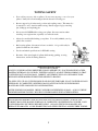
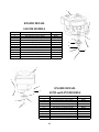
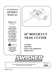
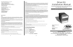
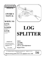
swisherinc.com
OWNER’S
MANUAL
MODEL NO.
LS722
STARTING SERIAL #:
L206-010001
LS10528
STARTING SERIAL #:
L206-010001
LS728
STARTING SERIAL #:
L206-010001
IMPORTANT
Read and follow all Safety
Precautions and Instructions
before operating this
equipment.
Rev. 06-010
LOG
SPLITTER
Safety
Assembly
Operation
Service and Adjustment
Repair Parts
1602 CORPORATE DRIVE, WARRENSBURG, MISSOURI 64093
FAX 660-747-8650
PHONE 660-747-8183
Manufacturing quality lawn care equipment since 1945
11253
Made In The
USA
LIMITED WARRANTY
The manufacturer’s warranty to the original consumer purchaser is: This product is free from defects in
materials and workmanship for a period of two (2) year from the date of purchase by the original consumer
purchaser. We will repair or replace, at our discretion, parts found to be defective due to materials or
workmanship. This warranty is subject to the following limitations and exclusions:
1)
Engine Warranty
2)
Commercial Use
3)
Limitation
4)
Exclusions
All engines utilized on our products have a separate warranty extended
to them by the individual engine manufacturer. Any engine service
difficulty is the responsibility of the engine manufacturer and in no
way is Swisher Mower Co., Inc. or its agents responsible for the engine
warranty. The Briggs & Stratton Engine Service Hot-Line is 1-800233-3723. The Tecumseh Engine Service Hot-Line is 1-800-558-5402.
The warranty period for any product used for commercial or rental is
limited to ninety (90) days from the date of original purchase.
This warranty applies only to products which have been properly
assembled, adjusted, and operated in accordance with the instructions
contained within this manual. This warranty does not apply to any
product of Swisher Mower Co., Inc., that has been subject to alteration,
misuse, abuse, improper assembly or installation, shipping damage, or
to normal wear of product.
Excluded from this warranty are normal wear, normal adjustments, and
normal maintenance. The pump, valve, and cylinder each carry separate
manufacture’s warranties. The valve and cylinder both carry a one (1) year
limited warranty. The pump carries a two (2) year limited warranty.
In the event you have a claim under this warranty, you must return the product to an authorized service dealer.
All transportation charges, damage, or loss incurred during transportation of parts submitted for replacement or
repair under this warranty shall be borne by the purchaser. Should you have any questions concerning this
warranty, please contact us toll-free at 1-800-222-8183. The model number, serial number, date of purchase,
and the name of the authorized Swisher dealer from whom you purchased the splitter will be needed before any
warranty claim can be processed.
THIS WARRANTY DOES NOT APPLY TO ANY INCIDENTAL OR CONSEQUENTIAL
DAMAGES AND ANY IMPLIED WARRANTIES ARE LIMITED TO THE SAME TIME PERIODS
STATED HEREIN FOR ALL EXPRESSED WARRANTIES. Some states do not allow the limitation of
consequential damages or limitations on how long an implied warranty may last, so the above limitations or
exclusions may not apply to you. This warranty gives you specific legal rights and you may have other rights,
which vary from state-to-state. This is a limited warranty as defined by the Magnuson-Moss Act of 1975.
TABLE OF CONTENTS
WARRANTY………………....….2
SAFETY..……………………….3-4
TOWING..….……..……………..5
OPERATION……………………6-8
MAINTENANCE.…………………….8
DECALS…..………….……………….9
PARTS BREAKDOWN…………….10-13
SPECIFICATIONS..…………………15
2
SAFETY PRECAUTIONS
This Safety Alert Symbol indicates important messages in this manual.
When you see this symbol, carefully read the message that follows and be
alert to the possibility of personal injury.
Read this manual completely. This machine can amputate hands, feet, and throw objects.
Failure to observe the following safety instructions could result in serious injury or death.
WARNING: The engine exhaust from this product contains chemicals known to the state of
California to cause cancer, birth defects or other reproductive harm.
DANGER: Your log splitter was built to be operated according to the rules for safe operation in
this manual. As with any type of power equipment, carelessness or error on the part of the
operator can result in serious injury. If you violate any of these rules, you may cause serious
injury to yourself or others.
•
Read the manual. Learn to operate this equipment in a safe manner.
•
Do not under any circumstances alter this log splitter. This equipment was designed and
engineered in accordance with operating instructions. Altering this equipment, or using
this equipment in such a way as to circumvent its design capabilities and capacities, could
result in serious injury or fatality and WILL VOID THE WARRANTY.
•
Allow only responsible adults who have read this manual to operate this machine. Never
allow children to operate this machine.
•
Never use splitter for any other purpose than splitting wood. Any other use can result in
injury. Your splitter is a precision piece of power equipment, not a toy. Therefore,
exercise extreme caution at all times.
•
Only a single operator is to load and operate the log splitter. Keep all others, including
pets and children, a minimum of 20 feet away from your work area. More accidents
occur when more than one person operates the log splitter than any other time.
•
Always disconnect the spark plug wire and place the wire where it cannot contact the
spark plug, to prevent accidental starting the engine when setting up, transporting,
adjusting or repairing.
•
Always wear protective gear such as safety goggles, protective hearing device, steel-toed
shoes, and tight-fitting gloves without drawstrings or loose cuffs.
•
Never wear loose clothing or jewelry that can be caught by moving parts of the splitter
and pull you into it. Keep hair away from moving parts.
•
Familiarize yourself with all of the controls in a safe environment before starting to work
with this machine.
3
Fluid escaping from a very small hole can be almost invisible. Do not check for leaks with your
hand. Escaping fluid under pressure can have sufficient force to penetrate skin, causing serious
personal injury. Leaks can be located by passing a piece of cardboard or wood over the suspected
leak and looking for discoloration. IF injured by escaping fluid, see a doctor at once. Serious
infection or reaction can develop if proper medical treatment is not administered
immediately.
•
Split only one log at a time. Never attempt to split two logs on top of each other.
•
Do not straddle or reach across the splitting area while operating the splitter.
•
Do not step over splitter when the engine is running. You may trip or accidentally
activate the splitting wedge. Walk around to get to the other side.
•
Never place hands or feet between log and splitting wedge or between log and ram during
forward or reverse stroke.
•
Never attempt to load splitter while splitting wedge is in motion. When loading log
splitter, place hands on the sides of the log, not the ends.
•
Only use your hands to operate the control lever. Never use foot, knee, rope or any
extension device.
•
Always keep fingers clear of splits that open in log during splitter operation.
•
When splitter is in the return mode, keep hands off the machine.
•
Only operate splitter on level ground, not on the side of a hill. It could tip or rolling logs,
poor footing, etc. could cause an accident.
•
Never operate or allow someone to operate this equipment while under the influence of
alcohol or drugs.
•
Always block the wheels to prevent movement while using splitter.
•
Never operate your splitter on wet, muddy, or icy surfaces. Safe footing is essential in
preventing accidents.
•
Never operate your splitter while it is attached to the tow vehicle.
•
Never make adjustments or repairs with the engine running.
•
Never attempt to split woods across the grain. Some types of wood may burst or fly out
of your splitter and result in injury.
•
Both ends of the log should be cut as squarely as possible to prevent the log from sliding
out of the splitter during operation. Log length should be kept to 24” or less.
4
TOWING SAFETY
•
Do not allow persons to ride on splitter. Do not carry any cargo or wood on your
splitter. It may fall off and endanger vehicles that are following you.
•
Be sure support leg is in the travel position and coupling secure. This must also
be retracted so not to interfere while towing. Retract support leg by removing
pin, sliding up, and replacing pin.
•
Never exceed 45 MPH while towing your splitter. Be extra cautious when
traveling over rough terrain, especially over railroad tracks.
•
Always be careful while backing your splitter. You could jackknife your log
splitter if not careful.
•
Before using splitter, disconnect it from tow vehicle. A log could easily be
pushed forward into the vehicle.
•
See tire and wheel specifications for PSI while towing.
•
Be aware of the extra length of splitter while turning, parking, crossing
intersections, and in all driving situations.
•
OPERATION INSTRUCTIONS
POSI-LOCK COUPLER
ADJUST COUPLER LOCKING PRESSURE ON BALL BEFORE USE. PLACE HANDLE IN LOCKED
POSITION WITH BALL IN COUPLER. TIGHTEN LOCKNUT AGAINST TENSION SPRING SO THAT
COUPLER IS NOT LOOSE ON BALL. CORRECT ADJUSTMENT WILL ALLOW HANDLE TO BE
RELEASED WITH MODERATE PRESSURE APPLIED TO HANDLE.
TO OPEN, PULL UP ON COUPLER HANDLE AND ROTATE FORWARD. PLACE COUPLER ON BALL
WHEN BALL IS COMPLETELY NESTED IN BALL SOCKET, ROTATE COUPLER HANDLE
BACKWARD UNTIL HANDLE IS IN LOCKED POSITION.
AFTER TOWING FOR 50 MILES, CHECK COUPLER FOR TIGHTNESS ON BALL. ALWAYS CHECK
TIGHTNESS BEFORE TOWING. BE SURE COUPLER HANDLE IS IN LOCKED POSITION.
WARNING:
NEVER EXCEED WEIGHT CAPACITY AND ALWAYS USE SAFETY CHAINS. ALWAYS USE
CORRECT BALL SIZE, MAKING SURE BALL IS COMPLETELY INSERTED INTO COUPLER. LOCK
COUPLER HANDLE SECURELY BEFORE TOWING. ALWAYS CHECK FOR DAMAGES AND
REPLACE IF DAMAGED. AVOID SHARP TURNS AND STEEP VERTICAL ANGLES WHEN TOWING.
5
OPERATION
Intended use: This log splitter is intended and designed to only split wood. NEVER use
for any other purposes. Doing so can cause injury or VOID THE WARRANTY.
ASSEMBLY INSTRUCTIONS
This log splitter has been partially assembled at the factory. Refer to the drawings and part
lists should it become necessary to disassemble the unit for repair or replacement of parts.
Inspect all components for damage.
WARNING: Exercise extreme caution, as parts are very heavy. Sufficient persons or
mechanical handling equipment should be used.
IMPORTANT: This unit is shipped with oil but without gasoline in the engine. After
assembly, see separate Engine Manual for proper fuel and oil recommendations.
FILLING THE HYDRAULIC RESERVOIR
Fill the hydraulic reservoir with at least 12 Quarts of Dextron III Automatic Transmission
fluid or 10W AW hydraulic fluid. After the hydraulic reservoir and the engine crankcase
are filled correctly with their respective oils, start the engine. Remember to set the throttle
and turn on the fuel shut-off valve. The hydraulic pump should prime itself. With the
engine running, move the hydraulic valve lever toward the wedge. This will cause the
cylinder to extend and expel air. When the cylinder is fully extended, retract it. Repeat
this procedure several times. (An erratic movement of the cylinder indicates that there is air
in the system). Once the cylinder has a smooth and constant speed indicating that all air
has been expelled, add another 4 quarts of oil, this should then bring the fluid level up to
approximately 3” below the fill hole. These models require approx. 16-17 Quarts of
hydraulic fluid.
NOTE: If the tank is overfilled, it will tend to expel oil from the breather cap when the
cylinder is retracted.
START UP
WARNING: DO NOT START OR RUN THE LOG SPLITTER WITHOUT OIL IN
THE ENGINE AND HYDRAULIC RESERVOIR.
See separate Engine Manual for fuel and oil recommendations. Your log splitter has come
equipped with a fuel shut-off valve for towing purposes.
Before starting engine make sure crankcase is filled correctly with oil and the proper fuel
has been used. The engine will only start when the throttle lever and fuel shut-off valve are
turned to their ON positions.
COLD WEATHER START UP
The Cold Weather Clutch enables the engine to be started without having to pull through
cold, thickened hydraulic fluid. Simply pull the handle out into locked position. Start
engine, let it warm up, and release Cold Weather Clutch. After starting, assure that the
lever has reengaged.
6
OPERATION
TOWING
This unit should not be towed on any street, highway, or public road without checking the existing
federal, local, and state laws. Any licensing or modifications such as taillights, etc., need to comply
with existing federal, local, or state vehicle requirements is the sole responsibility of the purchaser.
Obey all regulations when towing on public roads and highways. See also TOWING SAFETY.
Be sure you are using the correct ball hitch size for the hitch coupler on the log splitter (2” ball).
Be sure safety chains are properly connected. Leave enough slack in chains for turning. See
TOWING SAFETY to read warnings about coupling.
Make sure beam attachment is locked in the horizontal position. NEVER tow splitter in the vertical
position.
Turn the fuel shut-off valve OFF to prevent flooding of the engine while traveling.
TOWING AT NIGHT
The requirements for taillights are based on States regulations. Some states allow towing at night
as long as the towed equipment does not visibly impair the tow vehicle taillights. This is based on
a state, to state requirements. The customer is responsible for meeting the states requirements.
If a “Statement of Origin” is required in your state, see your local dealer to receive one.
OPERATION
1. Set up the log splitter in a clear, level area and block the wheels. The suction port on the
tank should always be on the lower side of the log splitter.
2. Place a log on the beam, against the foot plate. Make sure the log is securely on the foot
plate and up against the beam.
3. Depress the valve lever so that the cylinder will drive the wedge into the log. Extend the
cylinder until the log splits or to the end of its stroke. If the log has not completely split
after the cylinder has reached the end of its extension, retract the cylinder. NOTE:
Leaving the valve in the “actuate” position at the end of the stroke may damage the
pump.
OPERATING POSITIONS
WARNING: THE LOG SPLITTER BEAM IS HEAVY AND CAN PINCH HANDS/FINGERS IF
CARE IS NOT TAKEN.
STANDARD HORIZONTAL TO VERTICAL
The Standard Splitter has 2 operating positions: Horizontal, Vertical.
Remove pin from below beam. Do not remove bolt and nut. Rotate beam into vertical position and
pin so beam cannot fall into horizontal position.
DO NOT TOW IN VERTICAL POSITION!
IMPORTANT: When operating splitter in wooded areas, obtain a spark arrestor for the exhaust
system. See your local engine dealer.
When preparing logs, cut ends as square as possible. The maximum length of any logs should be
only 24”.
7
MAINTENANCE & STORAGE
WARNING: Disconnect spark plug before performing any maintenance or making adjustments.
RESERVOIR FLUID
Check the hydraulic fluid level in the reservoir tank before each use. Operating without an adequate oil
supply will cause severe damage to the pump. Change the hydraulic fluid in the reservoir per
manufacturers recommendations.
Be aware of the environment when disposing of used petroleum products. Please dispose of used
hydraulic fluid, engine oil and any by products from the maintenance of your log splitter at
approved recycling centers.
Should it become necessary to loosen or remove any hydraulic fitting or line, be sure to remove all
pressure by shutting off the engine and moving the control handle back and forth several times.
NEVER remove the cap from the hydraulic tank or reservoir while your unit is running. Hot oil
under pressure will cause injury.
Always store gasoline in an approved, tightly sealed container. Store container in a dry, cool place. Keep
fuel away from gas appliances where fumes could contact open flame, pilot lights or sparks.
Do not operate your splitter in poor mechanical condition or when needing repair. Repair and replace
worn or broken parts immediately.
Periodically tighten nuts, bolts, and hydraulic fittings.
The hydraulic system of your log splitter requires careful inspection, along with the mechanical parts. Be
sure to replace frayed, kinked, or otherwise damaged hydraulic components.
The pressure relief valve on the splitter is preset at the factory. Do not adjust valve. Only a qualified
service technician should perform this adjustment.
If the wedge becomes dull or nicked, it can be removed and sharpened. The wedge is heavy and may still
have sharp edges, wear gloves while handling the wedge.
REPAIR PARTS
Your Swisher Log Splitter has been produced with components designed specifically to this machine.
Although standard springs, hardware, etc. may look similar to parts used on other machinery, they may in
some cases be made of a different construction and/or materials.
8
SAFETY DECALS
Replace decals immediately if damaged.
OD16 – FUEL SHUT OFF DECAL
OD07 – COLD WEATHER DECAL
OD12 – HYDRAULIC FILL PLUG
DECAL
OD08 – OPERATOR INSTRUCTION
DECAL
OD09 – DANGER/POSITION LOCK
DECAL
9
ASSEMBLY DETAIL
LS722, LS10528, LS728 MODELS
10
SERVICE PARTS
Please have Model and Serial Numbers ready when ordering parts.
Color cannot be guaranteed upon service parts.
ITEM NUMBER
1
2
3
4
5
6
7
8
9
10
11
12
13
14
15
16
17
18
19
20
21
22
23
24
25
26
27
28
29
30
31
32
33
34
35
36
37
38
39
40
41
42
43
44
45
46
47
48
49
50
51
52
53
54
55
56
DESCRIPTION
54" Return Hose
48" Pressure Hose
#12 Hose Clamp
Return Line Fitting
Filter Head
Bolt 1/2-13 X 4 GR 5
Nut 1/2-13 Nyloc
Hydraulic Reservoir/Tank
1/2 X 3 1/2 Hitch Pin w/Hair Pin
Filter Element
3/4" NPT Filler Cap w/Hole
Bolt 3/8-16 X 3/4 Serr Flange
Nut 3/8-16 Serr Flange
Bolt 5/16-18 X 3/4 Serr Flange
Nut 5/16-18 Serr Flange
18" Suction Hose
#16 Hose Clamp
Hydraulic Pump-LS722 and LS728
Hydraulic Pump-LS10528
Pressure Line Fitting
Motor Base
Support Leg
Support Leg Bracket
3/8 X 2 1/2 Safety Hitch Pin
Tongue
Bolt 3/8-16 X 3 GR 5
Nut 3/8-16 Nyloc
Bolt 3/8-16 X 3 1/2 GR 5
W asher 3/8 SAE
2" Ball Coupler
Safety Chain w/ Hook
1/8 X 1/2 #3 W oodruff Key
Pump Pulley
5/16-18 X 1/2 Set Screw w/Loctite
38" Belt
Bolt 3/8-16 X 1 1/2 GR 5
Idler Bushing
Idler Spacer
Bolt 3/8-16 X 2 1/2 GR 5
Idler Arm
Idler Pulley
Nut 3/8-16 2-W ay Lock
Clutch Lever
Clutch Spring
Bolt 3/8-16 X 5 Turned Eye
Axle W eldment
Bearing Seal
Tapered Bearing
Tire & W heel
W asher 3/4ID X 1 1/4OD 10GA
Castle Nut
Cotter Pin
W heel Dust Cover
Log Splitter Folding Support Leg Txt Bk
Latch Pin Guide Bushing
1/2 X 3 Bent Pin with Hair Pin
3/8-16 X 4 HCC GR5 ZP
11
PART NUMBER
7290
7289
LS5001
7329
LS1112
NB132
NB281
11210TK
NB648
LS1113
7379
NB780
NB779
NB596
NB170
7346
LS4999
LS2001H
LS2002B
11248
11207TK
11220TK
11213TK
H11
11201TK
NB150
NB182
NB649
NB272
7365
7366
024002
7306
NB312
T38
NB107
6037
6040
NB619
6041TK
B527
NB280
11226TK
682S
11223
11199TK
2203S
2203B
7296
NB184
2203CN
NB633
2203DC
11494TK
7840Z
NB606
NB645
BEAM DETAIL
ALL MODELS
NOT ALL PARTS ARE ON ALL MODELS
ITEM NUMBER
1
2
3
4
5
6
7
8
9
10
11
12
13
14
15
16
17
18
19
20
21
22
DESCRIPTION
Beam W eldment
W edge W eldment
W edge GIB Angle
Bolt 3/8-16 X 1 1/4 Carriage
Nut 3/8-16 Nyloc
Nut 1/2-13 Nyloc Jam
1/2-13 X 3 1/2 GR5 ZP
Ram Cylinder - LS722 Model
Ram Cylinder - LS10528 and LS728 Model
2-W ay Pipe Nipple
Steel Pin
Clip Pin
Hydraulic Fitting
Stationary Line Assembly
Return Line Fitting
Valve Control
Valve Inlet Fitting
Valve Control Handle
Handle Grip
Master Chain Link
1/4 X 1 Clevis Pin
Cotter Pin
W asher
12
PART NUMBER
11293TC
11910TK
11857TK
10501
NB182
NB121
NB577
7284TK
7354TK
7292
7293
NB642
7291
7288TK
7329
7287TK
7387
7423
7425
7424
NB522
NB597
TR150W
1
2
ENGINE DETAIL
LS10528 MODELS
ITEM #
1
2
3
4
5
6
7
8
9
10
NOTSHOWN
NOTSHOWN
DESCRIPTION
Engine
Bolt 5/16-18 X 1 1/4 Serr. Flange
Nut 5/16-18 Serr. Flange
Upper Spacer
Engine Pulley
Lower Spacer
Washer
Washer Belleville
Bolt 7/16-20 X 1 GR 5 w/Loctite
1/4 X 1 Keystock
Fuel Shut Off Valve (Inline)
Fuel Line Clamp
PART #
N/A
NB253
NB170
689S
BB105
BB105S
TR150W
699
NB452N
9031
7414
6FLC
4
3
5
6
10
8
7
9
1
2
3
ENGINE DETAIL
4
5
6
4
8
7
9
LS722 and LS728 MODELS
ITEM #
1
2
3
4
5
6
7
8
9
NOTSHOW N
NOTSHOW N
DESCRIPTION
Engine
Bolt 5/16-18 X 2 1/4 Serr. Flange
Bolt 5/16-18 X 1 1/4 Serr. Flange
Nut 5/16-18 Serr. Flange
3/16 X 1 Keystock
5/16-18 X 1/2 Set Screw w/Loctite
Engine Pulley 7/8" ID
W asher Belleville
Bolt 3/8-24 X 1 w/Loctite
Fuel Shut Off Valve (Inline)
Fuel Line Clamp
13
PART #
N/A
NB622
NB253
NB170
9030
NB312
7323
699
NB238N
7414
6FLC
NOTES:
______________________________________________________________________
______________________________________________________________________
______________________________________________________________________
______________________________________________________________________
______________________________________________________________________
______________________________________________________________________
______________________________________________________________________
______________________________________________________________________
______________________________________________________________________
______________________________________________________________________
______________________________________________________________________
______________________________________________________________________
______________________________________________________________________
______________________________________________________________________
______________________________________________________________________
______________________________________________________________________
______________________________________________________________________
______________________________________________________________________
______________________________________________________________________
______________________________________________________________________
______________________________________________________________________
______________________________________________________________________
______________________________________________________________________
______________________________________________________________________
______________________________________________________________________
______________________________________________________________________
______________________________________________________________________
______________________________________________________________________
______________________________________________________________________
______________________________________________________________________
______________________________________________________________________
______________________________________________________________________
______________________________________________________________________
14
SPECIFICATIONS
LS722
Models
LS10528
LS728
Splitting
Force
22 Tons
28 Tons
28 Tons
Engine
7 Hp Briggs and
Stratton Intek OHV
10.5 HP Briggs
and Stratton I/C
7 Hp Briggs and
Stratton Intek OHV
Splitting
Positions
Horizontal and
Vertical
Horizontal and
Vertical
Horizontal and
Vertical
Cylinder
Size
4" X 24"
4 1/2" X 24"
4 1/2" X 24"
Pump
2 Stage with Heavy 2 Stage with Heavy 2 Stage with Heavy
Duty Bearings
Duty Bearings
Duty Bearings
Pump
Specs
11 Gallons Per
Minute
16 Gallons Per
Minute
11 Gallons Per
Minute
Valve
Auto Return
Auto Return
Auto Return
Drive
System
Belt Drive 1:1 Ratio Belt Drive 1:1 Ratio Belt Drive 1:1 Ratio
with Clutch for
with Clutch for
with Clutch for
Easy Starting
Easy Starting
Easy Starting
Oil
Capacity
16 Quarts
17 Quarts
17 Quarts
Maximum
Log length
25"
25"
25"
4.00 X 4.80 X 8
4.00 X 4.80 X 8
with High Speed
Bearings
Bearings
4.00 X 4.80 X 8
with High Speed
Bearings
Metal
Fenders
No
No
No
Ball Hitch
2" Ball
2" Ball
2" Ball
Unit
Weight
450 Lbs
490 Lbs
465 Lbs
Tire Specs with High Speed
15
LOG SPLITTER
OWNER’S
MANUAL
MODEL NO.
LS722
LS10528
LS728
HOW TO ORDER
REPAIR PARTS:
Each Log Splitter has its own serial number. Each engine has
its own serial number. The serial number for the Log Splitter
will be found on the right hand side of the hydraulic oil
reservoir. The serial number for the engine will be found on
the top of the blower fan housing.
All Log Splitter parts listed herein may be ordered directly
from Swisher Mower & Machine Co. Inc., your nearest
Swisher dealer, or from our website.
All engine parts may be ordered from the nearest dealer of the
engine supplied with your log splitter. Parts subject to change
without notice.
WHEN ORDERING PARTS, PLEASE HAVE THE
FOLLOWING INFORMATION AVAILABLE:
*
*
*
*
PRODUCT – SWISHER LOG SPLITTER
SERIAL NUMBER - _______________
MODEL NUMBER - _______________
ENGINE MODEL NUMBER - _______________
TYPE - _______________
* PART NUMBER
* PART DESCRIPTION
www.swisherinc.com
TELEPHONE - 1-800-222-8183
FAX - 1-660-747-8650
SWISHER MOWER & MACHINE CO. INC.
1602 CORPORATE DRIVE
WARRENSBURG, MO 64093
SWISHER MOWER & MACHINE CO. INC.
16