1
EN
SUUNTO
STINGER
USER’S GUIDE
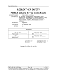
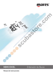
Present Depth
Maximum Depth
Average Depth in Logbook
Fast Ascent Warning
(SLOW)
ACW Indicator
Do Not Fly Icon
Arrows:
- Decompression Stop
at the Ceiling Depth
- Mandatory Safety Stop Zone
- Ascent Recommended
- Must Descend
Current Time Display
No-Decompression Time
Surface Interval Time
No Flying Time
Total Ascent Time
Ceiling Depth on Decompression Stop
Safety Stop Time
Mandatory Safety Stop Depth and Time
Bar Graph:
- Mode Indicator
- Oxygen Limit Fraction
Altitude Adjustment
Mode
Personal Adjustment
Mode
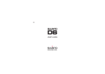
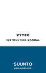
Bar Graph:
- Ascent Rate
- Battery Power
- Mode Indicator
Diver Attention Symbol
Temperature
Maximum Depth
Mode Text
Oxygen Percentage in Nitrox
Mode
Week Day
Timer Hours and Minutes
Low Battery Warning
AM/PM Indicator
Safety Stop Warning
Safety Stop Indicator
Dive Time
Dive Counter
Oxygen Partial Pressure
in Nitrox Mode
Time
Dual Time
Day, Month
Timer Seconds
Oxygen Partial Pressure
Daily Alarm
On Indicator
Dive Alarm
On Indicator
SUUNTO STINGER
QUICK REFERENCE GUIDE
DEFINITION OF WARNINGS, CAUTIONS AND NOTES
Throughout this manual, special references are made when deemed important. Three
classifications are used to separate these references by their order of importance.
WARNING is used in connection with a procedure or situation that may result
in serious injury or death.
CAUTION is used in connection with a procedure or situation that will result
in damage to the product.
NOTE
is used to emphasize important information.
COPYRIGHT, TRADEMARK AND PATENT NOTICE
This instruction manual is copyrighted and all rights are reserved. It may not, in
whole or in part, be copied, photocopied, reproduced, translated, or reduced to
any media without prior written consent from SUUNTO.
SUUNTO, STINGER, Oxygen Limit Fraction (OLF), SUUNTO Reduced Gradient
Bubble Model (RGBM), Continuous Decompression and their logos are all registered
or unregistered trademarks of SUUNTO. All rights are reserved.
Patents have been issued or applied for one or several features of this product.
CE
The CE mark is used to mark conformity with the European Union EMC directive
89/336/EEC. The SUUNTO dive instruments fulfill all the required EU directives.
1
FIOH, Laajaniityntie 1, FIN-01620 Vantaa, Finland, notified body no.0430, has EC
type-examined this type of personal protective equipment.
This instrument must be serviced by an authorized dealer every second year or after
500 dives (whichever comes first). See chapter 6.
PrEN 13319
PrEN 13319 "Diving accessories - Depth gauges and combined depth and time
measuring devices - Functional and safety requirements, test methods" is a European
diving depth gauge standard draft. The STINGER is designed to comply with this
draft standard.
ISO 9001
SUUNTO Oy's Quality Assurance System is certified by Det Norske Veritas to be
according to the ISO 9001 in all SUUNTO Oyj's operations (Quality Certificate No.
96-HEL-AQ-220).
SUUNTO Oy does not assume any responsibility for losses or claims by third parties,
which may arise through the use of this device.
Due to continuous product development, the STINGER is subject to change without
notice.
2
WARNING
Read this manual. Carefully read this instruction manual in its entirety paying
close attention to all warnings listed below, including chapter 1.1. "Safety
Precautions". Make sure that you fully understand the use, displays and limitations
of the dive computer because any confusion resulting from neglecting to follow
this instruction manual or from improper use of this device may cause a diver to
commit errors that may lead to serious injury or death.
WARNING
Not for professional use. Suunto dive computers are intended for recreational
use only. The demands of commercial or professional diving may expose the
diver to depths and exposures that tend to increase the risk of decompression
illness (DCI). Therefore, Suunto strongly recommends that the device be not
used for commercial or professional diving activity.
WARNING
Only divers trained in the proper use of scuba diving equipment should use a
dive computer. No dive computer can replace the need for proper dive training.
Insufficient or improper training may cause diver to commit errors that may lead
to serious injury or death.
3
WARNING
There is always a risk of decompression illness (dci) for any dive profile even if
you follow the dive plan prescribed by dive tables or a dive computer. no
procedure, dive computer or dive table will prevent the possibility of dci or oxygen
toxicity. An individual's physiological make up can vary from day to day. The
dive computer cannot account for these variations. You are strongly advised
to remain well within the exposure limits provided by the instrument to minimize
the risk of DCI. As an added measure of safety, you should consult a physician
regarding your fitness before diving.
WARNING
Suunto strongly recommends that sport divers limit their maximum depth to 40
m [130 ft] or to the depth calculated by the computer based on the selected O2%
and a maximum PO2 of 1.4 bar settings.
WARNING
Dives with required decompression stops are not recommended. you should
ascend and begin decompression immediately when the dive computer shows
you that a decompression stop is required. Note the blinking ASC TIME symbol
and the upward pointing arrow.
WARNING
Use back-up instruments. Make sure that you use back-up instrumentation
including a depth gauge, submersible pressure gauge, timer or watch, and have
access to decompression tables whenever diving with a dive computer.
4
WARNING
Perform prechecks. Always activate and check the device before diving in order
to ensure that all Liquid Crystal Display (LCD) segments are completely
displayed, that the device has not run out of battery power, and that the oxygen,
altitude and personal adjustments are correct. Also, exit the Data Transfer mode
before diving, as the computer does not automatically revert to Dive mode from
Data Transfer mode.
WARNING
You are advised not to fly any time the computer counts down the no-flying
time. always activate the computer to check the remaining no-fly time prior to
flying. The computer goes into the stand-by display automatically 5 minutes
after surfacing. Flying or traveling to a higher altitude within no-fly time can
greatly increase the risk of DCI. Review the recommendations given by Diver's
Alert Network (DAN) in chapter 3.2.3.4. "Flying After Diving". There can never
be a flying after diving rule that is guaranteed to completely prevent
decompression illness!
WARNING
The dive computer should never be traded or shared between users while it is in
operation. Its information will not apply to someone who has not been wearing it
throughout a dive or sequence of repetitive dives. Its dive profiles must match
that of the user. If it is left on the surface during any dive, it will give inaccurate
information for subsequent dives. No dive computer can take into account dives
made without the computer. Thus any diving activity up to four days prior to
initial use of the computer may cause misleading information and must be avoided.
5
WARNING
Do not dive with a cylinder of enriched air if you have not personally verified its
contents and entered the analyzed value into your dive computer. Failure to verify
cylinder contents and enter the appropriate O2% into your dive computer will
result in incorrect dive planning information.
WARNING
The dive computer will not accept fractional percentage values of oxygen
concentration. do not round up fractional percentages. For example, 31.8%
oxygen should be entered as 31%. Rounding up will cause nitrogen percentages
to be understated and will affect decompression calculations. If there is a desire
to adjust the computer to provide more conservative calculations, use the personal
adjustment feature to affect decompression calculations or reduce the PO2 setting
to affect oxygen exposure.
WARNING
Set the correct Altitude Adjustment Mode when diving at altitudes greater than
300 m [1000 ft] the Altitude Adjustment feature must be correctly selected in
order for the computer to calculate the decompression status. The dive computer
is not intended for use at altitudes greater than 3000 m [10000 ft]. Failure to
select the correct Altitude Adjustment setting or diving above the maximum
altitude limit will result in erroneous dive and planning data.
6
WARNING
Set the correct Personal Adjustment Mode. Whenever it is believed that factors
that tend to increase the possibility of DCI exist, it is recommended that you use
this option to make the calculations more conservative. Failure to select the correct
Personal Adjustment Setting will result in erroneous dive and planning data.
WARNING
Freediving after scuba diving is not recommended. It is recommended to avoid
freediving for at least two hours and not to exceed five meters [16 ft] after scuba
diving depending on your diving activity. Suunto also recommends you to be
trained in freediving technique and physiology before conducting breath holding
dives. No dive computer can replace the need for proper dive training. Insufficient
or improper training may cause diver to commit errors that may lead to serious
injury or death.
NOTE:
Free mode automatically changes to Gauge mode when the dive time exceeds five
minutes for a single dive. If the Stinger is in Gauge mode it is not possible to set it
to Air or EAN modes until 48 hours have passed. This does not apply to changing
between Free and Air or EAN modes.
Changing from Air to EAN mode is possible at any time. Changing from EAN to
Air mode however requires you to wait until the no-flying time has counted down.
7
TABLE OF CONTENTS
1. INTRODUCTION ........................................................................................ 12
1.1. SAFETY PRECAUTIONS ................................................................... 13
1.1.1. Emergency Ascents ..................................................................... 14
1.1.2. Dive Computer Limitations ......................................................... 14
1.1.3. Nitrox .......................................................................................... 15
1.1.4. Freediving ................................................................................... 15
2. GETTING ACQUAINTED .......................................................................... 17
2.1. FUNCTIONS ........................................................................................ 17
2.2. PUSH BUTTONS ................................................................................. 17
2.3. WATER CONTACTS ............................................................................ 18
2.4. TIME MODE [TIME] ........................................................................... 19
2.4.1. Timekeeping Display .................................................................. 20
2.4.2. Stopwatch [Timer] ....................................................................... 21
3. DIVING WITH THE STINGER .................................................................. 23
3.1 BEFORE DIVING ................................................................................. 24
3.1.1. Activation and Prechecks ............................................................ 24
3.1.2. Battery Power Indicator and Low Battery Warning .................... 26
3.1.3. User Definable Functions and Alarms ........................................ 28
3.1.3.1. Presetting Time Alarm .................................................... 29
3.1.3.2. Presetting Dive Alarms .................................................. 29
3.1.4. Bookmark .................................................................................... 29
8
3.2. SCUBA DIVING .................................................................................. 30
3.2.1. Diving with Air ........................................................................... 30
3.2.1.1. Dive Planning [PLAN] ................................................... 30
3.2.1.2. Presetting the Displays in the Air mode ......................... 32
3.2.1.3. Basic Dive Data .............................................................. 32
3.2.1.4. Safety stops ................................................................... 34
3.2.1.4.1. Recommended Safety Stop ................................. 35
3.2.1.4.2. Mandatory Safety Stop ........................................ 35
3.2.1.5. Ascent Rate Indicator ..................................................... 37
3.2.1.6. Decompression dives ..................................................... 39
3.2.2. Diving with EAN (Nitrox) .......................................................... 45
3.2.2.1. Before Diving ................................................................. 45
3.2.2.2. Presetting the Displays in the EAN mode ...................... 46
3.2.2.3. Oxygen Displays ............................................................ 47
3.2.2.4. Oxygen Limit Fraction (OLF) ........................................ 48
3.2.3. At the Surface .............................................................................. 49
3.2.3.1. Surface Interval after an Air/EAN Dive ......................... 49
3.2.3.2. Diver Attention Symbol ................................................. 51
3.2.3.3. Dive Numbering ............................................................. 51
3.2.3.4. Flying After Diving ........................................................ 52
3.2.4. High Altitude Dives and Personal Adjustment ............................ 53
3.2.4.1. Altitude Adjustment ....................................................... 53
3.2.4.2. Personal Adjustment ....................................................... 55
3.2.5. Error Conditions ......................................................................... 57
9
3.3. FREE / GAUGE MODE ....................................................................... 58
3.3.1. Before Diving in the Free/Gauge mode ...................................... 58
3.3.2. Presetting the Displays in the Free/Gauge mode ........................ 60
3.3.3. Freediving ................................................................................... 60
3.3.3.1. Freediving Day History .................................................. 61
3.3.4. Gauge mode ................................................................................ 62
3.3.5. Surface Interval After a Free/Gauge Dive ................................... 63
3.4. AUDIBLE AND VISUAL ALARMS ................................................... 65
4. SETTING MODE [SET] .............................................................................. 68
4.1. SETTING TIME, DATE AND DUAL TIME [TIME ] ........................ 68
4.2. DAILY ALARM SETTING [ALM] ..................................................... 70
4.3. AIR AND ENRICHED AIR NITROX SETTINGS [EAN] .................. 72
4.4. FREEDIVING AND GAUGE SETTINGS [FREE] ............................. 74
4.5. DIVE ALARM SETTINGS [DIVE AL] ............................................ 75
4.6. ALTITUDE, PERSONAL AND UNIT ADJUSTMENT SETTINGS ......
[AdJ] ..................................................................................................... 77
5. MEMORIES AND DATA TRANSFER [MEM] .......................................... 79
5.1. LOGBOOK AND DIVE PROFILE MEMORY [LOG] ....................... 80
5.2. DIVE HISTORY MEMORY [HIS] ...................................................... 85
5.3. DATA TRANSFER AND PC-INTERFACE [TR-PC] .......................... 86
6. CARE AND MAINTENANCE ................................................................... 89
6.1. CARE OF YOUR STINGER ................................................................ 89
6.2. MAINTENANCE ................................................................................. 91
6.3. WATER RESISTANCE INSPECTION ................................................ 92
10
7. TECHNICAL DESCRIPTION .................................................................... 93
7.1. OPERATING PRINCIPLES ................................................................. 93
7.2. REDUCED GRADIENT BUBBLE MODEL, SUUNTO RGBM ....... 96
7.3. OXYGEN EXPOSURE ........................................................................ 98
7.4. TECHNICAL SPECIFICATION ........................................................ 100
8. WARRANTY ............................................................................................. 105
9. GLOSSARY ............................................................................................... 107
11
1. INTRODUCTION
Congratulations on your purchase of the SUUNTO STINGER advanced dive
computer. The Stinger builds on the Suunto tradition of delivering feature-rich dive
computers. The Stinger provides many new and enhanced features that cannot be
found in any other dive computer. Push button controls access a wide selection of
choices. The display is optimized for the dive mode chosen and it incorporates the
patented user definable display field. This dive computer is a compact and
sophisticated multipurpose dive instrument, designed to give you years of troublefree service.
CHOICE OF DIVING AND WATCH MODES
User options for the Stinger are selected using the push buttons. Pre dive configuration
and setup options include:
12
Choice of operating mode - Air / Nitrox / Free/Gauge
Maximum depth alarm
Dive time alarm
Mix Oxygen fraction % (Nitrox mode only)
Oxygen partial pressure alarm limit
Altitude adjustment
Personal adjustment
Choice of unit - Metric / Imperial
Clock, calendar, daily alarm, stopwatch, dual time
User definable display fields
CONTINUOUS DECOMPRESSION WITH SUUNTO RGBM
The Suunto Reduced Gradient Bubble Model (RGBM) utilized in the Stinger predicts
both dissolved and free gas in blood and tissues of divers. It is a significant advance
on the classic Haldane models, which do not predict free gas. The advantage of
Suunto RGBM is additional safety through its ability to adapt to a variety of situations
and dive profiles.
In order to optimize how to respond to different added risk situations an additional
category of stop, referred to as a Mandatory Safety Stop, has been introduced. Also
a countdown for the Recommended Safety Stop is included. The combination of
stop types will depend on the specific dive situation.
To get the most from the safety benefits be sure to read the summary of the Suunto
Reduced Gradient Bubble Model in chapter 7.2.
1.1. SAFETY PRECAUTIONS
Do not attempt to use Stinger without reading this instruction manual in its entirety,
including all the warnings. Make sure that you fully understand the use, displays
and limitations of the instrument. If you have any questions about the manual or the
dive computer, contact your SUUNTO dealer before diving with the dive computer.
Always remember that you are responsible for your own safety.
When used properly, the dive computer is an outstanding tool for assisting properly
trained, certified divers in planning and executing sport dives. It is not a substitute
for certified scuba instruction, including training in the principles of decompression.
13
Diving with enriched air mixtures (nitrox) exposes the user to risks different from
those associated with diving with standard air. These risks are not obvious and require
training to understand and avoid. Risks include possible serious injury or death.
Do not attempt to dive with any gas mix other than standard air without first receiving
certified training in this specialty.
1.1.1. EMERGENCY ASCENTS
In the unlikely event that Stinger malfunctions during a dive, follow the emergency
procedures provided by your certified dive training agency or, alternatively,
STEP 1: Assess the situation calmly and then move promptly to less than 18 m
[60 ft].
STEP 2: At 18 m [60 ft], slow down your ascent rate to 10 m/min [33 ft/min] and
move to a depth between 3 and 6 meters [10 to 20 ft].
STEP 3: Stay there as long as you assess your air supply will safely allow. After
reaching the surface stay out of the water for at least 24 hours.
1.1.2. DIVE COMPUTER LIMITATIONS
While the dive computer is based on current decompression research and technology,
you must realize that the computer cannot monitor the actual physiological functions
of an individual diver. All decompression schedules currently known to the authors,
including the U.S. Navy Tables, are based on theoretical mathematical models, which
are intended to serve as a guide to reduce the probability of decompression illness.
14
1.1.3. NITROX
Diving with nitrox provides the diver with an opportunity to reduce the risk of
decompression illness by reducing the nitrogen content in the breathing gas mix.
However, when the gas mix is altered, the oxygen content of the mix is generally
increased. This increase exposes the diver to an oxygen toxicity risk not usually
considered in recreational diving. In order to manage this risk, the dive computer
tracks the time and intensity of the oxygen exposure and provides the diver with
information to adjust the dive plan in order to maintain oxygen exposure within
reasonably safe limits.
In addition to the physiological effects of enriched air on the body there are operational
considerations to be addressed when handling altered breathing mixes. Elevated
concentrations of oxygen present a fire or explosion hazard. Consult with the
manufacturer of your equipment about its compatibility with nitrox.
1.1.4. FREEDIVING
Freediving, and particularly freediving in combination with scuba diving, may have
risks that have not been researched and are not commonly known.
Any person who engages in any form of breathhold diving is in danger of shallowwater blackout (SWB) i.e. the sudden loss of consciousness caused by oxygen
starvation.
Any breathhold diving results in some nitrogen build-up in the blood and other fast
tissues. Due to the short time spent at depth this build-up is generally not significant.
15
Therefore, provided the effort involved in freediving has not been severe, there is
little risk in diving after breathhold diving. However, the converse is more unknown
and may increase significantly the risk of DCI. Therefore, FREEDIVING AFTER
SCUBA DIVING IS NOT RECOMMENDED. You should avoid freediving and
not exceed five meters [16 ft] for at least two hours after scuba diving.
Suunto also recommends you to be trained in freediving technique and physiology
before conducting breathhold dives. No dive computer can replace the need for proper
dive training. Insufficient or improper training may cause a diver to commit errors
that may lead to serious injury or death.
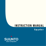
Fig. 2.1. The push buttons of the
Stinger.
16
2. GETTING ACQUAINTED
2.1. FUNCTIONS
The STINGER Advanced Computer Watch is a multipurpose dive instrument and a
sport watch featuring several watch and dive computer modes. You can select the
dive computer model between the Regular Air Dive Computer (AIR), Enriched Air
Nitrox Dive Computer (EAN) and Freediving computer / Depth Gauge with Timer
mode (FREE). The Air/EAN and Free modes can also be disabled (set to OFF) and
the instrument can be used as a sports watch on land or in water.
2.2. PUSH BUTTONS
The Stinger is controlled with four push buttons as follows (see Fig. 2.1.).
M (MODE)
To change from a main mode to an other main mode press the mode button.
To exit from a submode to a main mode press the mode button.
To activate the electroluminescent backlight hold down the mode button
for more than two seconds or one second in the diving mode.
To accept the settings in the Setting Mode press the mode button.
S (SELECT)
To select a submode press the select button.
To select the active segment in the Setting Mode press the select button.
17
To select the display in the Logbook Mode press the select button.
To select the dive planning mode in the dive surface modes.
To make a special bookmark in the profile memory during a dive and to
operate the timer in the Gauge mode.
To show the date, seconds or dual time in the time keeping display press
the + or - button.
In the Setting Mode
to increase the value press the + button
to decrease the value press the - button.
To operate the stopwatch see chapter 2.4.2.
To select the dive in the Logbook Mode
press the + button to move forward
press the - button to move backwards.
+, -
2.3. WATER CONTACTS
The water contact is located on the right side of the case (Fig. 2.2.). When submerged
the contact is connected to the case by the conductivity of the water and the Surface
or Diving Mode is automatically activated.
Contamination or dirt on the water contact may prevent this automatic operation. It
is, therefore, important that the water contact is kept clean. The contact can be cleaned
with fresh water and a soft brush (e.g. tooth brush).
18
NOTE: Water or moisture build-up around the water
contact may cause the contact to activate automatically.
This can happen, e.g., when washing your hands or
sweating. If the water contact activates in the Time
Mode, an ACW text will appear on display (Fig. 2.3.),
and it will be shown until the water contact deactivates,
or the Stinger enters the Dive Mode automatically. To
save the battery power, you should deactivate the water
contact by cleaning it and/or drying it with a soft towel.
2.4. TIME MODE [TIME]
The Stinger has dual time, calendar clock, stopwatch
and alarm clock functions. The calendar clock and the
stopwatch are operated in the Time Mode. The mode
is indicated by the TIME text and the mode indicator
in the display (Fig. 2.4.). The time, dual time, date and
the daily alarm are set in the Setting Mode (see chapter
4).
Fig. 2.2. The water contact and
depth sensor.
Fig. 2.3. Active water contact is
indicated by the text ACW.
19
2.4.1. TIMEKEEPING DISPLAY
The timekeeping display is the primary display of
the Stinger (Fig. 2.5.). When the Time Mode is entered
from other modes, the timekeeping display activates
within two seconds, if no button is operated.
In other modes (except in the Diving or Stopwatch
Modes), if no button is operated within 5 minutes, the
Stinger beeps and returns to the timekeeping display
automatically.
Fig. 2.4. The Time Mode is
indicated by the TIME text and
a mode indicator.
a)
Either the date (a), the seconds of the current time (b)
or dual time (c) are shown on the bottom line of the
timekeeping display. Press the + or - button to select
the desired display option. Next time when you enter
the timekeeping display, the Stinger will show the
selected option. The TIMER text blinks on the display
if the stopwatch is running.
b)
TIME
c)
Fig. 2.5. The time keeping display
a) the date is displayed
b) the seconds are displayed
c) the dual time is displayed.
20
The display is illuminated by holding down the M
button for more than two seconds.
To set the time and date, refer to chapter 4.1 "Setting
Time, Date and Dual Time".
When diving, the dive entry time and date is registered
in the Logbook Memory. Remember always to check
before diving that the time and date are correctly set,
especially when traveling to different time zones.
2.4.2. STOPWATCH [TIMER]
The Stopwatch function is entered by pressing the S
button, when the time keeping display is shown. The
text TIMEr at the bottom and the mode indicator
(TIME) on the left side of the display indicate that you
have entered the Stopwatch function (Fig. 2.6.).
The stopwatch of the Stinger lets you measure elapsed
time, split times and the times of two runners. The range
of the stopwatch is 9 hours, 59 minutes, 59.9 seconds
(Fig. 2.7.). When the range is exceeded the computer
watch gives a beep and returns to the time keeping
display automatically.
Fig. 2.6. The Stopwatch function
is indicated by the TIMEr text
and a mode indicator.
TIMER
Fig. 2.7. The Stopwatch displays
hours, minutes and seconds.
21
Use the + and - buttons to operate the elapsed time measurement, split time
measurement or the times of two runners as follows:
(ODSVHGWLPHPHDVXUHPHQW 6SOLWWLPHPHDVXUHPHQW
7LPHVRIWZRUXQQHUV
6WDUW
6WDUW
6WDUW
6WRS
6SOLW
6SOLWWLPHRIWKHILUVWUXQQHU
5HVWDUW
6SOLWUHOHDVH
6WRS
6WRS
6WRS
6SOLWUHOHDVHWLPHRIWKHVHFRQG
UXQQHU
&OHDU
&OHDU
&OHDU
Diving with the Stinger or data transfer will stop the stopwatch. However, it is possible
to use stopwatch function when diving, if the Air/EAN and Free -diving modes are
disabled (set to OFF, see chapter 3.2.). There is also a separate stopwatch (dive
timer) that can be used when diving in the Free/Gauge mode (see chapter 3.3.).
22
3. DIVING WITH THE STINGER
In order to familiarize yourself with the menu based
functions, Suunto recommends you use your Quick
Reference Guide supplied with the Stinger together with
the information in the following chapters.
This section contains instructions on how to operate the
dive computer and interpret its displays. You will find
that this dive computer is easy to use and read. Each
display shows only the data relevant to that specific
diving situation.
Fig. 3.1. Chosen Dive Mode.
Chapter 3.1. Before Diving contains general instructions
for all the dive computer modes. Chapter 3.2. Scuba
Diving information for air and enriched air nitrox scuba
diving and Chapter 3.3. Free / Gauge Mode information
for freediving or diving in the gauge mode.
Fig. 3.2. Startup I. All segments
shown.
23
a)
3.1 BEFORE DIVING
3.1.1. ACTIVATION AND PRECHECKS
b)
c)
The instrument can be activated by pressing the M
button or it will activate the scuba dive computer mode
(default) or freedive mode according the user selection,
if submerged deeper than 0.5 m (1.5 ft).
The chosen Dive Mode is indicated by the Air, EAN or
Free texts and mode indicator on the right side of the
display (Fig. 3.1.). Next, all display elements will turn
on showing mostly figure 8's and graphical elements
(Fig. 3.2.). A few seconds later the battery power
indicator is shown and the backlight and the buzzer are
activated (Fig. 3.3a.). Next, the screen will display the
mode dependent Ready display confirming that the
activation is complete (Fig. 3.4.).
At this time, perform your precheck making sure that:
d)
the Stinger operates and provides a complete
display
the low battery indicator is not on
the instrument displays correct units
Fig. 3.3. Startup II. Battery power indicator.
24
the instrument displays correct temperature
and depth (0.0 m [0 ft])
the buzzer beeps
you have preset desired displays on the User
Definable Display Field
the altitude and personal adjustment settings
are correct (Air and EAN modes)
m
SURF TIME
DIVE TIME
°C
TIME
And if set to EAN mode, make sure that:
the oxygen percentage is adjusted according
to the measured Nitrox blend in your cylinder
the oxygen partial pressure limit is set
correctly.
Fig. 3.4. Startup III. Surface mode
(Air). Depth and dive time are zero.
Pressing +/- button activates
alternative display of maximum
depth and current time.
The Stinger is now ready for diving.
NOTE: The surface interval time does not run before
the first dive.
MAX
m
TIME
DIVE
Fig. 3.5. Startup IV. Free/Gauge mode. Depth and dive time
are zero. Pressing +/- button activates alternative display of
maximum depth and current time or dive number.
25
After activation of the Dive Mode or after diving, the Stinger will automatically
switch to show the time keeping display within 5 minutes to conserve the battery
power, if you do not press any buttons. However, the dive computer functions will
remain active until it has calculated that all residual nitrogen has off-gassed. This
may take up to 100 hours, as described in chapter 7.1. "Operating Principles".
However, SUUNTO recommends to turn on the Dive Mode before diving to check
the settings, battery warning, etc. and for dive planning.
3.1.2. BATTERY POWER INDICATOR AND LOW BATTERY
WARNING
This dive computer has a unique graphic Battery Power Indicator designed to give
you an advance notice of impending need to change the battery.
The Battery Power Indicator can always be seen as the Dive Mode is activated. The
electroluminescent backlight will be on during the battery check. The following
Table and Figure show the various warning levels.
26
TABLE 3.1. BATTERY POWER INDICATOR
Display
Operation
Figure
3.3
BAT +
4 segments
Normal, full battery.
a)
BAT +
3 segments
Normal, battery power is getting low or the
temperature is low.
Battery replacement is recommended if you
are going to colder conditions or if you are
planning to make a dive trip.
b)
BAT + LOW +
Battery power is low and the battery
2 segments +
replacement is recommended.
low battery symbol The battery symbol is displayed.
The backlight is disabled.
c)
BAT + ERR
Change the battery!
1 segment +
Returns to the Time display.
low battery symbol Activation and all functions are disabled.
d)
Temperature or an internal oxidation of the battery affects the battery voltage. If the
instrument is stored for a long period, the low battery warning may be displayed
even though the battery has enough capacity. The low battery warning may also be
displayed at low temperatures, even though the battery has enough capacity in warmer
conditions. In these cases repeat the battery check procedure.
27
After the battery check the Low Battery Warning is
indicated by the battery symbol (Fig. 3.6.).
If the battery symbol is displayed in the Surface mode
or if the display is faded or weak, the battery may be
too low to operate the dive computer and battery
replacement is recommended.
Fig. 3.6. Low Battery Warning.
Battery symbol indicates that the
battery is low and battery
replacement is recommended.
NOTE: For safety reasons the backlight cannot be
activated when the low battery warning is indicated by
the battery symbol.
3.1.3. USER DEFINABLE FUNCTIONS
AND ALARMS
This Stinger has several User Definable Functions and
depth and time related alarms that you can set according
to your personal preference. For example the Stinger
has a patented presetting system for the User Definable
Display Field in the lower part of the display.
28
Fig. 3.7. Bookmark activation.
An annotation, Bookmark, is
placed in the profile memory
during a dive by pressing the S
button (Displayed with Diver
Attention symbol.).
The displays can be preset in the Surface Mode. If it is not active, enter it by selecting
the Dive Mode. The preset display will remain active until another display is selected.
The preset displays will be the default displays in the Diving Mode. The other
available display can be accessed by pressing the + or - button. After five seconds
the display changes back to the default preset display automatically.
3.1.3.1. PRESETTING TIME ALARM
The alarm clock is set in the Setting Mode, ALM. For further information see chapter
4.2.
3.1.3.2. PRESETTING DIVE ALARMS
The dive alarms (dive time alarm and maximum depth alarm) are set in the Setting
Mode, DIVE AL. For further information see chapter 4.5.
3.1.4. BOOKMARK
It is possible to make special marks in the profile memory during a dive. These
Bookmarks will be shown as a Diver Attention Symbol when scrolling the profile
memory on the computer display (Fig. 3.7). The Bookmarks will also be shown as
annotations in the PC-software, Suunto Dive Manager. To make a bookmark on the
profile memory during a dive press the S button. The Diver Attention Symbol will
be displayed to confirm the bookmark. In the Gauge mode pressing the S button also
resets the stopwatch.
29
3.2. SCUBA DIVING
3.2.1. DIVING WITH AIR
3.2.1.1. DIVE PLANNING [PLAN]
It is possible at any time in the Air/EAN Surface Mode to enter the Planning Mode,
simply by pressing the S button. After showing the text PLAN and the mode indicator
(Fig. 3.8.), the display will show the no-decompression limit for the depth of 9 m [30
ft]. By pressing the + button, the Stinger will calculate and show the next deeper nodecompression limits in 3 m [10 ft] increments ending at 45 m [150 ft] or at the
maximum allowed depth in the EAN mode. By pressing the - button the next shallower
depth will be shown again.
The Planning Mode can be canceled by pressing the M or the S button.
NOTE: The Planning mode is disabled in the Air/EAN Error mode (see chapter
3.2.5.).
Higher Altitude and conservative Personal Adjustment Modes will shorten the nodecompression time limits. These limits at different Altitude and Personal Adjustment
Mode selections are shown in Table 7.1. and 7.2.
30
The Planning mode also accounts for the following
information from previous dives:
any calculated residual nitrogen
all dive history for the past four days
oxygen exposure (EAN mode)
The no-decompression times given for different depths
will therefore be shorter than before your first "fresh"
dive.
DIVE NUMBERING SHOWN DURING
DIVE PLANNING
Fig. 3.8. Dive Planning. The
Planning mode is indicated by
the PLAN text and mode
indicators.
Dives belong to the same repetitive dive series if the
instrument was still counting down the no-fly time at
the beginning of the dive.
The surface interval must be at least 5 minutes for a
dive to be considered a repetitive dive. Otherwise, it is
considered a continuation of the same dive. The dive
number will not change and the dive time will continue
where it left off (see chapter 3.2.3.3.).
Fig. 3.9. Planning. The nodecompression time limit at 30.0
m [100 ft] is 18 minutes in P0/
A0 mode.
31
3.2.1.2. PRESETTING THE DISPLAYS IN
THE AIR MODE
Preset with the - button in the lower left corner of the
display (Fig. 3.4.):
Fig. 3.10. Dive has just begun.
Available no-decompression
time is more than 199 min.
the maximum depth or
the temperature.
Preset with the + button in the lower right corner of the
display (Fig. 3.4.):
the dive time or
the current time.
3.2.1.3. BASIC DIVE DATA
The dive computer will remain in the Surface mode at
depths less than 1.2 m [4 feet]. At depths greater than
1.2 m the instrument will go into the Diving mode (Fig.
3.10.).
Fig. 3.11. Diving display. Present depth is 19.3 m [63 ft] and no-decompression
stop time limit is 23 minutes in A0/P1 mode. Maximum depth during this dive has
been 19.8 m [65 ft], elapsed dive time is 16 minutes. Alternative display shows
temperature and current time.
32
During a no-decompression stop dive, the following information will be displayed
(Fig. 3.11.):
your present depth in meters [ft]
the Altitude Adjustment setting on the right side of the center window with
a wave and mountain symbols (A0, A1, or A2) (see Table 3.3.)
the Personal Adjustment setting on the right side of the center window with
a diver symbol and + signs (P0, P1, or P2) (see Table 3.4.)
the available no-decompression time in minutes in the center window as
NO DEC TIME. It is calculated based on the five factors described in
chapter 7.1. "Operating Principles".
the maximum depth during this dive in meters [ft], indicated as MAX or
the temperature in °C [°F] in the lower left corner.
the elapsed dive time in minutes, indicated as DIVE TIME or the current
time, indicated as TIME in the lower right corner.
33
3.2.1.4. SAFETY STOPS
Safety stops are widely considered "good diving
practice" and are an integral part of most dive tables.
Reasons to perform a safety stop include a reduction in
sub clinical DCI, microbubble reduction, ascent control,
and orientation before surfacing.
Fig. 3.12. A three minute
Recommended Safety Stop.
The Stinger displays two different types of safety stops:
Recommended Safety Stop and Mandatory Safety Stop.
The Safety Stops are indicated by:
Fig. 3.13. Mandatory Safety
Stop. You are advised to make a
mandatory Safety Stop in the
zone between the ceiling and
floor.
34
STOP label, when in the depth range 3 m - 6
m [10 ft - 20 ft] = Recommended Safety Stop
Countdown which is activated when the depth
of 10 m [30 ft] is exceeded.
STOP+ CEILING label, when in the depth
range 3 m - 6 m [10 ft - 20 ft] = Mandatory
Safety Stop Time display
STOP label, when deeper than 6 m =
Mandatory Safety Stop scheduled
3.2.1.4.1. RECOMMENDED SAFETY STOP
With every dive over 10 meters the instrument has a three minute countdown for
the recommended safety stop, to be taken in the 3 - 6 meter [10 ft - 20 ft] range. This
is shown with the STOP sign and a three-minute countdown in the center window
instead of the no-decompression time (Fig. 3.12.).
The Recommended Safety Stop, as the name implies, is recommended. If it is ignored,
there is no penalty applied to the following surface intervals and dives.
3.2.1.4.2. MANDATORY SAFETY STOP
When the ascent rate exceeds 12 meters/min [40 ft] momentarily or 10 meters/min
[33ft] continuously the micro-bubble build-up is predicted to be more than allowed
for in the decompression model. The Suunto RGBM calculation model responds to
this by adding a Mandatory Safety Stop to the dive. The time of this Mandatory
Safety Stop will depend on the severity of the ascent rate excess.
The STOP sign will appear in the display and when you reach the depth zone between
6 m to 3 m [20 ft to 10] also the CEILING label, ceiling depth and the calculated
Safety Stop time appear in the display. You should wait until the Mandatory Safety
Stop warning disappears (Fig. 3.13.).
The Mandatory Safety Stop time always includes the three minute Recommended
Safety Stop time. The total length of the Mandatory Safety Stop time depends on the
seriousness of the ascent rate violation.
35
Fig. 3.14. Violated Mandatory
Safety Stop. Downward pointing
arrow and an audible alarm
indicate you should descend to
ceiling zone.
36
You must not ascend shallower than 3 m [10 ft] with
the Mandatory Safety Stop warning on. If you ascend
above the Mandatory Safety Stop ceiling, a downward
pointing arrow will appear and a continuous beeping
starts (Fig. 3.14.). You should immediately descend to,
or below, the Mandatory Safety Stop ceiling depth. If
you correct this situation at any time during that dive,
there are no affects on the decompression calculations
for future dives.
If you continue to violate the Mandatory Safety Stop,
the tissue calculation model is affected and the dive
computer shortens the available no-decompression time
for your next dive. In this situation, it is recommended
to prolong your surface interval time before your next
dive.
3.2.1.5. ASCENT RATE INDICATOR
The ascent rate is shown graphically along the left side of the display as follows:
TABLE 3.2. ASCENT RATE INDICATOR
Ascent Rate Indicator
The equivalent ascent speed
Example
in Fig.
No segments
Below 4 m/min [13 ft/min]
3.10
One segment
4 - 6 m/min [13 - 20 ft/min]
3.11
Two segments
6 - 8 m/min [20 - 26 ft/min]
3.12
Three segments
8 - 10 m/min [26 - 33 ft/min]
3.13
Four segments
10 - 12 m/min [33 - 39 ft/min]
3.14
Four segments, the
SLOW segment, blinking
depth reading, the STOP
sign and an audible alarm
Above 12 m/min [39 ft/min] or
continuously above 10 m/min
[33 ft/min]
3.15
When the maximum allowed ascent rate is exceeded, the SLOW warning and the
STOP sign appear, indicating that the maximum ascent rate has been exceeded
continuously or that the current ascent rate is significantly above the allowed rate.
37
Fig. 3.15 Ascent Rate Indicator.
Blinking SLOW and four
segments are shown together
with an audible alarm: ascent rate
is more than 10 m/min [33 ft/
min]. This is a caution to slow
down! STOP sign means that you
are advised to make a Mandatory
Safety Stop when you reach a
depth of 6 m [20 ft].
38
Whenever the SLOW warning segment and the STOP
sign appear (Fig. 3.15.), you should immediately slow
down your ascent. When you reach the depth zone
between 6 m to 3 m [20 ft to 10 ft] the STOP and
CEILING depth labels will advise you to make a
Mandatory Safety Stop. Wait until the warning
disappears (Fig. 3.13.). You should not ascend shallower
than 3 m [10 ft] with the Mandatory Safety Stop warning
on.
WARNING
Do not exceed the maximum ascent rate! Rapid
ascents increase the risk of injury. You should
always make the Mandatory and Recommended
Safety Stops after you have exceeded the maximum
recommended ascent rate. If this Mandatory Safety
Stop is not completed the decompression model will
penalize your next dive(s).
3.2.1.6. DECOMPRESSION DIVES
When your NO DEC TIME becomes zero, your dive becomes a decompression stop
dive, i.e. you must perform one or several decompression stops on your way to the
surface. The NO DEC TIME on your display will be replaced by a CEILING and
blinking ASC TIME notation and an upward pointing arrow (Fig. 3.17.).
If you exceed the no-decompression limits on a dive, the dive computer will provide
decompression information required for ascent. After this, the instrument will continue
to provide subsequent interval and repetitive dive information.
Rather than requiring you to make stops at fixed depths, the dive computer gives
you the option to decompress with a more gradual and natural series of mini steps
within the decompression range (continuous decompression).
Fig. 3.16. Ceiling, ceiling zone,
floor and decompression range.
39
The ascent time (ASC TIME) is the minimum amount of time needed to reach the
surface in a decompression dive. It includes:
time needed to ascend to the ceiling at an ascent rate of 10 m/min [33 ft/
min] plus
time needed at the ceiling. The ceiling is the shallowest depth where
decompression could be made plus
time needed at the Mandatory Safety Stop (if any) plus
3 minute Recommended Safety Stop plus
time needed to reach the surface after the ceiling and safety stops have been
completed.
WARNING
Your ascent time may increase if you:
- ascend slower than 10 m/min [33 ft/min] or
- make your decompression stop deeper than at the ceiling.
These factors will also increase the amount of air required to reach the surface.
40
CEILING, CEILING ZONE, FLOOR AND DECOMPRESSION
RANGE
When in decompression, it is important that you understand the meaning of ceiling,
floor, and decompression range (Fig. 3.16.):
The ceiling is the shallowest depth where decompression could be made.
At this depth, or below, you must perform all stops.
The ceiling zone is the optimum decompression stop zone. It is the zone
between the minimum ceiling and 1.8 m [6 ft] below the minimum ceiling.
The floor is the deepest depth at which the decompression stop time will
not increase. Decompression will start when you pass this depth during
your ascent.
The decompression range is the depth range between the ceiling and floor.
Within this range, decompression takes place. However, it is important to
remember that the decompression will be very slow at, or close to, the floor.
The depth of the ceiling and floor will depend on your dive profile. The ceiling depth
will be fairly shallow when you enter the decompression mode, but if you remain at
depth, it will move downward and the ascent time will increase. Likewise, the floor
and ceiling may change upwards while you are decompressing.
41
When conditions are rough, it may be difficult to
maintain a constant depth near the surface. In this case
it will be more manageable to maintain an additional
distance below the ceiling, to make sure that the waves
do not lift you above the ceiling. Suunto recommends
that decompression takes place deeper than 4 m [13 ft],
even if the indicated ceiling is shallower.
Fig. 3.17. Decompression dive,
below floor. Upward pointing
arrow, blinking ASC TIME label
and an audible alarm tell you to
ascend. Minimum total ascent
time including safety stop is 7
minutes. Ceiling is at 3 m [10 ft].
NOTE: It will take more time and more air to
decompress below the ceiling than at the ceiling.
WARNING
Never ascend above the ceiling! You must not
ascend above the ceiling during your
decompression. In order to avoid doing so by
accident, you should stay somewhat below the
ceiling.
Fig. 3.18. Decompression dive, above floor. Upward pointing
arrow has disappeared and ASC TIME label has stopped blinking,
which means that you are in the decompression range.
42
DISPLAY BELOW THE FLOOR
The blinking ASC TIME and an upward pointing arrow
indicate that you are below the floor (Fig. 3.17.). You
should start your ascent immediately. The ceiling depth
is shown on the left and the minimum total ascent time
on the right side of the center window.
DISPLAY ABOVE THE FLOOR
When you ascend above the floor, the ASC TIME
display stops blinking and the upward pointing arrow
disappears (Fig. 3.18.). Decompression will now begin,
but is very slow. You should therefore continue your
ascent.
Fig. 3.19. Decompression dive,
at ceiling zone. Two arrows point
at each other ("hour glass"). You
are in the optimum ceiling zone
at 3.5 m [11 ft] and your
minimum ascent time is 5
minutes.
DISPLAY AT THE CEILING ZONE
When you reach the ceiling zone, the display will show
you two arrows pointing at each other (the "hour glass"
icon, Fig. 3.19.). Do not ascend above this zone.
During the decompression stop, ASC TIME will count
down towards zero. When the ceiling moves upwards,
you can ascend to the new ceiling. You may surface
43
only after the ASC TIME and CEILING labels have
disappeared, which means that the decompression stop
and any Mandatory Safety Stop has been completed.
You are advised, however, to stay until the STOP sign
has also gone. This indicates that the three minute
Recommended Safety Stop has also been completed.
DISPLAY ABOVE THE CEILING
Fig. 3.20. Decompression dive,
above ceiling. Note downward
pointing arrow, Er warning and
an audible alarm. You should
immediately (within 3 minutes)
descend to or below ceiling.
If you ascend above the ceiling during a decompression
stop, a downward pointing arrow will appear and a
continuous beeping starts (Fig. 3.20.). In addition, an
error warning Er reminds you that you have only three
minutes to correct the situation. You must immediately
descend to or below the ceiling.
If you continue to violate the decompression, the dive
computer goes into a permanent Error Mode. In this
mode the instrument can only be used as a depth gauge
and timer. You must not dive again for at least 48 hours
(see chapter 3.2.5.).
44
3.2.2. DIVING WITH EAN (NITROX)
3.2.2.1. BEFORE DIVING
This dive computer can be set for diving with standard air only (Air mode) or it can
be set for diving with Enriched Air Nitrox (EAN mode).
If set to the EAN mode, the correct oxygen percentage of the gas in your cylinder
must always be entered into the computer to ensure correct nitrogen and oxygen
calculations. The dive computer adjusts its mathematical nitrogen and oxygen
calculation models according to the entered O2% value (Fig. 3.21.). Calculations
based on Nitrox result in longer no-decompression times and shallower maximum
depths.
DEFAULT NITROX SETTINGS
In the EAN mode, the default setting is for standard air (21% O2). It remains in this
setting until the O2% is adjusted to any other percentage of oxygen (22% - 50%).
If a dive is started within 2 hours Stinger retains this value until the dive series is
finished. If unused, the computer will retain the manually entered value for the selected
oxygen percentage for about two hours, after which it will revert to the default setting
of 21% O2.
The default setting for maximum oxygen partial pressure is 1.4 bar, however you
are able to set it in the range of 1.2 - 1.6 bar.
45
3.2.2.2. PRESETTING THE DISPLAYS IN
THE EAN MODE
MAX
When entering the EAN mode the oxygen percentage
and partial pressure are always the default displays in
the lower part of the display.
Preset with the - button in the lower left corner of the
display (Fig. 3.22.):
Fig. 3.21. Nitrox display.
Maximum depth based on set
O2% (21%) and PO2 (1.4 bar) is
54.1 m [177 ft].
Preset with the + button in the lower right corner of the
display (Fig. 3.22.):
Fig. 3.22. Diving in EAN mode.
The O2% is set to 32%.
46
oxygen percentage (default)
the maximum depth or
the temperature.
current oxygen partial pressure
the dive time or
the current time.
3.2.2.3. OXYGEN DISPLAYS
If set to EAN mode the NITROX display, with all
labeled oxygen information, is shown immediately after
activation. The nitrox display shows (Fig. 3.21.):
oxygen percentage, labeled with O2%, is
shown in the left side of the lower display
set oxygen partial pressure limit, labeled with
PO2, is shown in the right side of the lower
display
maximum allowed depth based on the set
oxygen percentage and partial pressure limit
current oxygen toxicity exposure shown with
an Oxygen Limit Fraction (OLF) bar graph
along the right side of the display.
In the Dive mode the current oxygen toxicity exposure
is always shown with an Oxygen Limit Fraction (OLF)
bar graph and the oxygen percentage labeled with O2%.
The current oxygen partial pressure labeled with PO2
is also shown, if selected (Fig. 3.22.). During a dive,
the oxygen partial pressure, labeled with PO2, is always
shown instead of the preselected display, if the partial
pressure is greater than 1.4 bar or the set value (Fig.
3.23.).
Fig. 3.23. Oxygen partial
pressure and OLF displays.
There is an audible alarm and the
last segment of the bar graph
starts to blink as the OLF has
reached 80% limit. When OLF
has reached 100%, all segments
starts to blink. If the OTU value
is higher than the CNS value, the
lowest segment blinks.
47
3.2.2.4. OXYGEN LIMIT FRACTION (OLF)
In addition to tracking the diver's exposure to nitrogen, the instrument tracks the
exposure to oxygen. These calculations are treated as entirely separate functions.
The dive computer calculates separately for Central Nervous System oxygen toxicity
(CNS) and Pulmonary Oxygen toxicity, the latter measured by the addition of Oxygen
Toxicity Units (OTU). Both fractions are scaled so that the maximum tolerated
exposure for each is expressed as 100%.
The Oxygen Limit Fraction (OLF) bar graph has 7 segments, each representing
12,5% (from 1 to 50%) or 15% (from 50% to 80%). The OLF bar graph displays
only the value of the higher of the two calculations. When the OTU value meets and
exceeds the CNS value then in addition to displaying its percentage the lowest segment
blinks to indicate that the value shown relates to OTU. The oxygen toxicity
calculations are based on the factors listed in chapter 7.3. "Oxygen Exposure".
48
3.2.3. AT THE SURFACE
3.2.3.1. SURFACE INTERVAL AFTER AN AIR/EAN DIVE
An ascent to any depth shallower than 1.2 m [4 ft] will cause the DIVING display to
be replaced by the alternating SURFACE displays, giving the following information
(Fig. 3.24. and 3.25.):
maximum depth of most recent dive in meters [ft]
present depth in meters [ft]
the surface time in hours and minutes (separated by a colon), telling the
duration of the present surface interval
the desaturation/no-flying time in hours and minutes is shown next to the
airplane in the center window of the display
no-flying warning indicated by an airplane icon
Altitude Adjustment setting
Personal Adjustment setting
Diver Attention symbol indicates if you should prolong your surface interval
time
STOP label for 5 min, if the Mandatory Safety Stop was violated
ASC TIME, if the decompression ceiling was violated (= Error Mode)
(Fig. 3.26.)
49
Or in the lower display according the selection and
mode:
Fig. 3.24. Surface display. You
have surfaced from a 18 minute
dive, which maximum depth was
20.0 m [66 ft]. The present depth
is 0.0 m [0 ft] and surface interval
time is 0. Airplane symbol
indicates that you should not fly
and diver attention symbol
indicates that you should prolong
your surface interval time
because of excess micro-bubbles.
50
dive time of most recent dive in minutes
labeled with DIVE TIME.
the current time labeled with TIME
oxygen partial pressure labeled with PO2 (if
set to EAN mode)
maximum depth labeled with MAX
the current temperature with °C for Centigrade
[or °F for Fahrenheit]
oxygen percentage setting labeled with O2%
(if set to EAN mode)
If set to EAN mode, the current oxygen toxicity exposure
is shown with an Oxygen Limit Fraction (OLF) bar
graph along the right side of the display.
Fig. 3.25. Surface display.
Alternating display showing the
no-flying time.
3.2.3.2. DIVER ATTENTION SYMBOL
The Diver Attention Symbol is an advice to extend
surface interval. Some patterns of diving, in particular
multiday diving with many dives and short surface
intervals, cumulatively add a higher risk of DCI. When
this is detected in addition to adapting the decompression
algorithm, the Diver Attention Symbol is shown.
3.2.3.3. DIVE NUMBERING
Several repetitive dives are considered to belong to the
same repetitive dive series when the dive computer has
not counted the no-flying time to zero. Within each
series, the dives are given individual numbers. The first
dive of the series will be numbered as DIVE 1, the
second as DIVE 2, the third as DIVE 3, etc.
If you start a new dive with less than 5 minutes of surface
interval time, the dive computer interprets this as a
continuation of the previous dive and the dives are
considered to be the same. The diving display will
return, the dive number will remain unchanged, and
Fig. 3.26. Surface Mode after a
violated decompression dive.
ASC TIME symbol indicates that
you have violated the ceiling for
more than three minutes. The
alternating display shows you
that you must not dive again for
at least 48 hours.
Diver Attention Symbol
Violated Decompression
Ceiling
Do Not Fly Symbol
51
the dive time will begin where it left off. After 5 minutes on the surface, subsequent
dives are, by definition, repetitive. The dive counter displayed in the Planning Mode
will increment to the next higher number if another dive is made.
3.2.3.4. FLYING AFTER DIVING
The no-flying time is shown in the center window next to the airplane image. Flying
or travelling to a higher altitude should be avoided at any time the computer counts
down the no-flying time.
The no-flying time is always at least 12 hours or equivalent to the so-called
desaturation time (if longer than 12 hours).
In the permanent Error mode and Free/Gauge mode the no-flying time is 48 hours.
Divers Alert Network (DAN) recommends the following on no-flying times:
52
A minimum surface interval of 12 hours would be required in order to be
reasonably assured a diver will remain symptom free upon ascent to altitude
in a commercial jetliner (altitude up to 2400 m [8000 ft]).
Divers who plan to make daily, multiple dives for several days, or make
dives that require decompression stops, should take special precautions
and wait for an extended interval beyond 12 hours before flight. Further,
the Undersea and Hyperbaric Medical Society (UHMS) suggests divers
using standard air tanks and exhibiting no symptoms of decompression
illness wait 24 hours after their last dive to fly in an aircraft with cabin
pressure up to 2400 m [8000 ft]. The only two exceptions to this
recommendation are:
If a diver had less than 2 hours total accumulated dive time in the last 48
hours, then a 12 hour surface interval before flying is recommended.
Following any dive that required a decompression stop, flying should be
delayed for at least 24 hours, and if possible, for 48 hours.
Suunto recommends that flying is avoided until all the DAN and UHMS
guidelines and the dive computer wait to fly conditions are satisfied.
3.2.4. HIGH ALTITUDE DIVES AND PERSONAL
ADJUSTMENT
The dive computer can be adjusted both for diving at altitude and also to increase
the conservatism of the mathematical nitrogen model.
3.2.4.1. ALTITUDE ADJUSTMENT
When programming the instrument for the correct altitude, you need to select the
correct Altitude Mode according to Table 3.3. The dive computer will adjust its
mathematical model according to the entered altitude mode, giving shorter nodecompression times at higher altitudes (see chapter 7.1., Table 7.1. and 7.2.).
53
TABLE 3.3. ALTITUDE ADJUSTMENT RANGES
$OWLWXGH
PRGH
6\PERO
RQGLVSOD\
$OWLWXGH
UDQJH
$
P>IW@
$
P>IW@
$
P>@
The entered Altitude Adjustment Mode is indicated by mountain symbols (A0, A1
= one mountain, or A2 = two mountains). Also, the maximum altitudes are displayed
for each Altitude group (see Table 3.3.). Chapter 4.6. describes how the Altitude
Mode is adjusted.
Traveling to a higher elevation can temporarily cause a change in the equilibrium of
dissolved nitrogen in the body. It is recommended that you acclimate to the new
altitude by waiting at least three hours before making a dive.
54
3.2.4.2. PERSONAL ADJUSTMENT
There are adverse personal factors for DCI which divers can predict in advance and
input into the decompression model. Factors that may affect susceptibility to
decompression illness vary between divers and also for the same diver from one day
to another. The three-step Personal Adjustment Mode is available, if a more
conservative dive plan is desired.
The personal factors which tend to increase the possibility of DCI include, but are
not limited to:
cold exposure - water temperature less than 20 °C [68 °F]
the diver is below average physical fitness level
diver fatigue
diver dehydration
previous history of DCI
stress
obesity
The Personal Adjustment Mode is indicated by a diver symbol and plus signs (P0 =
a diver, P1 = diver +, or P2 = diver ++). Chapter 4.6. describes how the Personal
Mode is adjusted.
55
This feature should be used to adjust the computer to be more conservative, according
to personal preference, by entering the suitable Personal Adjustment Mode with the
help of Table 3.4. In ideal conditions, retain the default setting, P0. If conditions are
more difficult or other mentioned factors which tend to increase the possibility of
DCI exist, select P1 or even the most conservative P2. As a result the dive computer
adjusts its mathematical model according to the entered Personal Adjustment Mode,
giving shorter no-decompression times (see chapter 7.1., Table 7.1. and 7.2.).
TABLE 3.4. PERSONAL ADJUSTMENT RANGES
3HUVRQDO
PRGH
56
6\PERO
RQGLVSOD\
&RQGLWLRQ
3
,GHDOFRQGLWLRQ
3
6RPHPHQWLRQHGIDFWRUV
RUFRQGLWLRQVH[LVW
3
6HYHUDOPHQWLRQHGIDFWRUV
RUFRQGLWLRQVH[LVW
'HVLUHG
WDEOHV
'HIDXOW
3URJUHVVLYHO\
PRUH
FRQVHUYDWLYH
3.2.5. ERROR CONDITIONS
The dive computer has warning indicators that alert the user to react to certain
situations that would significantly increased the risk of DCI. If you do not respond
to its warnings, the dive computer will enter an Error Mode, indicating that the risk
of DCI has greatly increased. If you dive sensibly, it is very unlikely you will ever
put the instrument into the Error Mode.
OMITTED DECOMPRESSION
The Error Mode results from omitted decompression, i.e. when you stay above the
ceiling for more than three minutes. During this three-minute period the Er warning
is shown and the audible alarm beeps. After this, the dive computer will enter a
permanent Error Mode. The instrument will continue to function normally if you
descend below the ceiling within this three-minute period.
Once in the permanent Error Mode only the Er warning is shown in the center window.
The dive computer will not show times for ascent or stops. However, all the other
displays will function as before to provide information for ascent. You should
immediately ascend to a depth of 3 to 6 m [10 to 20 ft] and remain at this depth until
air supply limitations require you to surface.
The Error mode will stay for 48 hours, during which time you should not dive.
Whilst Stinger is in Error mode the ASC TIME label will be displayed in the center
window and the Planning Mode will be disabled.
57
3.3. FREE / GAUGE MODE
3.3.1. BEFORE DIVING IN THE FREE/GAUGE MODE
If set to Free/Gauge mode, the dive computer can be used for freediving or diving
with technical diving mixed gases. If you are trained for free or technical diving and
you plan to use Free/Gauge mode on a regular basis, it may be preferable to disable
the Air/EAN mode to set the instrument permanently to its Free/Gauge mode (see
chapter 4.3.).
The default sampling interval for the logbook profile memory in the Free/Gauge
mode is 4 seconds, but it can be set to 2, 10, 20, 30 or 60 seconds. This can be done
in the Free setting mode (see chapter 4.4). It is advisable to use the short sampling
rates for freediving but the longer ones (10 to 60s) for Scuba diving. Shorter intervals
enable more accurate stored dive profiles. If your sampling rate is less than 10 seconds,
your maximum dive time is 200 minutes.
The Dive Time display in the center window can be changed during a dive to become
a stopwatch. When this stopwatch option is used the center display cannot be reset to
Dive Time during the current dive. Using the stopwatch function has no effect on
another Dive Time setting which can be preset or called up in the user definable
display.
58
NOTE: The number of hours of dive time available
depends on the sampling rate. A computer set to record
depth every 4 seconds will fill its memory sooner than
the same computer set to 30 seconds. The number of
available hours also depends on the length of each dive.
Fewer longer dives means more total hours of dive time
available in the memory than does a large number of
short dives.
NOTE: The dive time shown on the Logbook/Profile
memory is always shorter or equal to the dive time
shown in the surface display depending on the sampling
rate.
Fig. 3.27. Free/Gauge Mode.
If set to Free/Gauge mode the text FREE is shown after
activation (Fig. 3.27.)
59
m
3.3.2. PRESETTING THE DISPLAYS IN
THE FREE/GAUGE MODE
Preset with the - button in the lower left corner of the
display (Fig. 3.28.)
DIVE TIME
°C
Fig. 3.28. Surface display/
Alternative display.
m
DIVE
°C
Fig. 3.29. Free dive. Present
depth is 6.1 m, dive time 1.03
min and dive number is 1.
60
the maximum depth or
the temperature.
Preset with the + button in the lower right corner of
the display (Fig. 3.28.)
the dive time,
the current time or
the dive number.
3.3.3. FREEDIVING
In the Free/Gauge mode the present depth is always
shown. Maximum depth and temperature or dive time,
current time and dive number are shown in the
alternative displays.
In addition to the Dive Time display in the lower right
corner of the display, the Free Dive Time in minutes
and seconds is shown in the center window (Fig. 3.29.)
By pressing the S button you get a bookmark
3.3.3.1. FREEDIVING DAY HISTORY
It is possible at any time in the Free Surface Mode to
enter the Freediving Day History Mode, simply by
pressing the S button. After showing the text DAY HIS
and the mode indicator (Fig. 3.30.), the display will show
(Fig. 3.31.):
the total amount of free dives,
the longest free dive in minutes and seconds
in the center window and
the deepest free dive made during that day.
Fig. 3.30. Freediving Day History.
The Day His Mode can be canceled by pressing the M
or the S button.
m
DIVE
Fig. 3.31. Day History display.
61
3.3.4. GAUGE MODE
The Free mode automatically changes to Gauge mode
when the dive time exceeds five minutes for a single
dive. In addition to the displays shown in the Free mode
the Ascent Rate indicator is now enabled.
In the Free/Gauge mode the Dive Time in the center
window can also be used as an automatic Stop Watch.
When the SELECT button is pressed during the dive:
Fig. 3.32. Surface display after
Free dive. Center window
showing surface time.
A special mark, bookmark is written in the
profile memory.
The Dive Time shown in the center window is
stopped, reset and started again.
NOTE: If you make a Gauge mode dive, it is not
possible to change between the modes within 48 hours.
Fig. 3.33. Alternating surface
display after Free dive. Center
window showing the dive time
of the most recent dive.
62
3.3.5. SURFACE INTERVAL AFTER A
FREE/GAUGE DIVE
An ascent to any depth shallower than 1.2 m [4 ft] will
cause the DIVING display to be replaced by the
SURFACE display, giving the following information
(Fig. 3.32. and 3.34.):
maximum depth of most recent dive in meters
[ft]
present depth in meters [ft]
the surface time in hours and minutes
(separated by a colon), telling the duration of
the present surface interval.
m
Fig. 3.34. Surface display after
Gauge dive. Center window
showing surface time.
AFTER A FREEDIVE:
dive time of most recent dive in minutes and
seconds in the center window (Fig. 3.33.).
Fig. 3.35. Alternating display
after Gauge dive. Center window
showing the no-flying time.
63
AFTER A SCUBA DIVE IN THE GAUGE MODE:
the no-flying time in hours and minutes is shown next to the airplane in the
center window of the display (Fig. 3.35.)
no-flying warning indicated by an airplane icon.
Or in the lower display according the selection:
dive time of the most recent dive in minutes labeled with DIVE TIME.
the current time labeled with TIME
the dive number labeled with DIVE
maximum depth labeled with MAX
the current temperature with °C for Centigrade [or °F for Fahrenheit].
NOTE: After a Gauge mode dive the no-flying time is always 48 h.
NOTE: Dive numbering in the Free/Gauge mode is different than in the Air/EAN
mode. It is based on repetitive dives made during one day. The dive number is zeroed
at midnight.
64
3.4. AUDIBLE AND VISUAL ALARMS
The dive computer features audible and visual alarms to advise when important
limits are approached or to acknowledge preset alarms.
A short single beep occurs when:
when the dive computer automatically returns to the Time mode.
Three single beeps with a two second interval and the backlight activated for
5 seconds occur when:
the no-decompression dive turns into a decompression stop dive. An arrow
pointing upwards and the blinking ascent warning ASC TIME will appear
(Fig. 3.17.).
Continuous beeps and the backlight activated for 5 seconds occur when:
the maximum allowed ascent rate, 10 m/min [33 ft/min], is exceeded.
SLOW and STOP warnings will appear (Fig. 3.15.).
the Mandatory Safety Stop ceiling is exceeded. A downward pointing arrow
will appear (Fig. 3.14.).
the decompression ceiling depth is exceeded. An error warning Er and a
downward pointing arrow appear. You should immediately descend to, or
below, the ceiling. The instrument will otherwise enter a permanent Error
Mode within three minutes, indicated by a permanent Er (Fig. 3.20.).
65
You are able to preset alarms before the actual dive. The user programmable alarms
can be set for maximum depth, dive time and daily time. The alarms activate when:
The preset maximum depth is reached
- continuous beep series for 24 seconds or until any button is pressed.
- the maximum depth blinks as long as the present depth value exceeds the
adjusted value.
The preset dive time is reached
- continuous beep series for 24 seconds or until any button is pressed.
- the dive time blinks for one minute, if no button is pressed.
The preset alarm time is reached
- the current time is shown.
- continuous beep series for 24 seconds or until any button is pressed.
- the current time blinks for one minute, if no button is pressed.
OXYGEN ALARMS IN EAN MODE
Three double beeps and the backlight activated for 5 seconds occur when:
the OLF bar graph reaches 80%. The segments exceeding the 80% limit
start to blink (Fig. 3.23.)
the OLF bar graph reaches 100%. All the OLF bar graph segments start to
blink.
The blinking of the segments will stop when the OLF is not loading anymore. At
that point the PO2 is less than 0.5 bar.
66
Continuous beeps for 3 minutes and the backlight activated for 5 seconds
occur when:
the set oxygen partial pressure limit is exceeded. The maximum depth is
replaced with the current blinking PO2 value. You should immediately
ascend above the PO2 depth limit (Fig. 3.23.).
WARNING
When the oxygen limit fraction indicates that the maximum limit is reached, you
must immediately ascend until the warning stops blinking! Failure to take action
to reduce oxygen exposure after the warning is given can rapidly increase the
risk of oxygen toxicity and the risk of injury or death.
67
4. SETTING MODE [SET]
The time, date, dual time, daily alarm, scuba and free
dive selections and settings, dive time and depth alarms
and the altitude, personal and unit adjustments are set
in the Setting Mode (Fig. 4.1.).
Fig. 4.1. The Setting Mode is
indicated by the SET text and
mode indicator.
Enter the Setting Mode from other modes by pressing
the M button. The text SET at the bottom and the mode
indicator on the left side of the display indicate the
selected mode
4.1. SETTING TIME, DATE AND
DUAL TIME [TIME ]
To set the time and date:
1. In the Setting Mode, press S to select the Time
Adjustment Mode (Fig. 4.2.).
Fig. 4.2. Time Adjustment Mode.
68
2. Wait two seconds until the Time Adjustment Mode
activates automatically. The time mode indicator
appears and the second digits start to blink on the display
(Fig. 4.3.).
3. Press S to change the selection in the following
sequence:
-> seconds -> hours -> minutes -> 12/24 hour format
-> year -> month -> day -> dual (home) time hours ->
minutes
4. While the second digits are selected (blinking), press
- to reset the seconds to "00" or press + to increase the
value.
5. While any other digits (except seconds) are selected
(blinking), press + to increase the value or - to decrease
it. Holding the button the current selection starts to
scroll.
Fig. 4.3. The Time Adjustment
Mode is activated and the second
digits are blinking. Page I.
6. After you have set the time and date, press the M
button to save the settings and to return to the Setting
Mode [SET].
NOTE:
The day of the week is automatically calculated in
accordance with the date.
The date can be set within the range of Jan 1, 1990 to
Dec. 31, 2089.
Fig. 4.4. The year, month and day
is selected. Page II. Dual time
selected. Page III.
69
NOTE:
While the selection is blinking and no button is
operated within 10 minutes, the blinking stops and the
Stinger beeps and returns automatically to the
timekeeping display.
The display is illuminated by holding down the M
button for more than two seconds.
Fig. 4.5. Daily alarm Setting
Mode.
4.2. DAILY ALARM SETTING [ALM]
You can set one daily alarm in the Stinger. When the
daily alarm activates, the -symbol blinks for 1 minute
and the alarm sounds for 24 seconds. The alarm is given
at the preset time each day. Press any button to stop the
audible alarm, after it has activated.
To set the daily alarm:
1. In the Setting Mode, press S two (2) times to select
the Daily alarm Setting Mode (Fig. 4.5.).
Fig. 4.6. Daily Alarm Setting
Mode is activated.
70
2. Wait two seconds until the Daily Alarm Setting Mode
activates automatically. The time mode indicator
appears and the alarm status [On/OFF] starts to blink
on the display (Fig. 4.6.).
3. Press S to change the selection in the following sequence:
-> On/OFF status -> hours -> minutes
4. While the alarm status [On/OFF] is selected (blinking) press + or - to change the
status. When the alarm status is On, the daily alarm indicator ( -symbol) in the
bottom right corner of the display indicates that the alarm is on.
5. Set the other sections as follows:
While any other digits (except alarm status) are selected (blinking), press + to
increase the value or - to decrease it. Holding down either button starts the scrolling
of the current selection.
The 12-hour or 24-hour format of the alarm matches the format of the timekeeping
display, which is selected in the Time Adjustment Mode (see chapter 4.1.). When
using the 12-hour format of the alarm, take care to set the time correctly as morning
(AM) or afternoon (PM).
6. After you have set the daily alarm, press the M button to save the settings and to
return to the Setting Mode [SET].
71
4.3. AIR AND ENRICHED AIR
NITROX SETTINGS [EAN]
In this setting mode you can either select one scuba dive
mode (standard air and enriched air nitrox) or disable
both. If you select ON then you have a choice of whether
to have either Standard Air or Enriched Air Nitrox as
the operating option.
Fig. 4.7. EAN/Air Setting Mode.
If set to the EAN (Nitrox) mode, the correct oxygen
percentage of the gas in your cylinder must always be
entered into the computer to ensure correct nitrogen and
oxygen calculations. Also in EAN mode, the oxygen
partial pressure limit must be set. When in the EAN
Setting mode the equivalent allowed maximum depth
based on the chosen setting will also be displayed.
To set the Air/EAN:
1. In the Setting Mode, press S three (3) times to select
the EAN Setting Mode (Fig. 4.7.).
Fig. 4.8 The enable/disable status
of the EAN Mode.
72
2. Wait two seconds until the EAN Setting Mode
activates automatically. The enable/disable status [On/
OFF] starts to blink on the display (Fig. 4.8.).
3. Press S to change the selection in the following
sequence:
-> On/OFF status -> EAN/AIR -> if EAN selected:
Oxygen percentage (O2%) -> Oxygen partial pressure
(PO2)
While the enable/disable status [On/OFF] is selected
(blinking) press + or - to change the status. When the
Air/EAN dive mode is selected (blinking) press + or to change the mode. When Oxygen percentage (O2%)
or Oxygen partial pressure (PO2) are selected (blinking)
press + or - to change the setting (Fig. 4.9.).
Fig. 4.9. Setting Oxygen
Percentage and Partial Pressure.
4. After you have set the EAN, press the M button to
save the settings and to return to the Setting Mode [SET]
NOTE: If the EAN/Air mode is disabled (set to OFF),
the instrument will not activate the scuba diving mode
when submerged.
Fig. 4.10. Free Setting Mode.
73
4.4. FREEDIVING AND GAUGE
SETTINGS [FREE]
In this setting mode you can select or disable the freedive
mode and set the freedive sampling rate.
To set the FREE:
1. In the Setting Mode, press S four (4) times to select
the Free Setting Mode (Fig. 4.10.).
Fig. 4.11. The enable/disable
status of the Free Mode and the
recording rate setting.
2. Wait two seconds until the Free Setting Mode
activates automatically. The enable/disable status [On/
OFF] starts to blink on the display (Fig. 4.11.).
3. Press S to change the selection in the following
sequence:
->On/OFF status -> Freediving recording rate in seconds
Fig. 4.12. Dive Alarm Setting
Mode.
74
While the enable/disable status [On/OFF] is selected
(blinking) press + or - to change the status. When the
REC mode is selected (blinking) press + or - to change
the setting. Available settings are 2, 4, 10, 20, 30, 60
seconds (Fig. 4.11.).
4. After you have set the FREE, press the M button to
save the settings and to return to the Setting Mode
[SET].
NOTE: If both the Air/EAN and Free modes are
disabled (set to OFF), the instrument will not activate
any diving mode when submerged.
4.5. DIVE ALARM SETTINGS
[DIVE AL]
You can set one depth alarm in the Stinger. When the
depth alarm activates, the -symbol blinks as long as
the present depth value exceeds the adjusted value and
the alarm sounds for 24 seconds. Press any button to
stop the audible alarm, after it has activated.
Fig. 4.13. Dive Time Alarm.
Center window displays less than
5 minutes dive time.
To set the depth alarm:
1. In the Setting Mode [SET], press S five (5) times to
select the Dive Alarm Setting Mode (Fig. 4.12.).
2. Wait two seconds until the Dive Alarm Setting Mode
activates automatically. The alarm status [On/OFF]
starts to blink on the display (Fig. 4.13.).
Fig. 4.14. Dive Time Alarm.
Display when more than 5
minutes dive time left.
75
3. Press S to change the selection in the following
sequence.
-> On/OFF status -> depth alarm limit -> dive time
alarm minutes (-> dive time alarm seconds)
Fig. 4.15. Adjustment Mode.
4. While the alarm status [On/OFF] is selected
(blinking), press + or - to change the status. When the
alarm status is On, the depth alarm indicator ( symbol) in the bottom right corner of the display
indicates that the alarm is on.
5. While the depth digits are selected (blinking), press
+ to increase the value or - to decrease it at intervals of
0.5 m [1 ft]. Holding down either button starts the
scrolling of the depth value. The range of the depth is
from 3.0 to 150 m [10 to 450 ft]. The default setting is
40m [131ft]. If set to 0, the alarm is disabled.
Fig. 4.16. Setting Altitude
Adjustment.
76
6. While the dive time minutes are selected (blinking),
press + or - to change the time. If the time is less than
five (5) minutes, the dive time alarm seconds can also
be set. This feature can be used for freediving (Fig.
4.13.)
7. After you have set the depth alarm, press the M button
to save the settings and to return to the Setting Mode
[SET].
4.6. ALTITUDE, PERSONAL AND
UNIT ADJUSTMENT SETTINGS
[AdJ]
The current Altitude and Personal Adjustment Modes
are shown when diving as well as at the surface. If the
mode does not match the altitude or conditions (see
chapter 3.2.4.), it is imperative that the diver enters the
correct selection before diving. Use the Altitude
Adjustment to select the correct altitude mode. Use the
Personal Adjustment to add an extra level of
conservatism. In this setting mode also the desired units
can be selected (metric, m/°C or imperial, ft/°F).
Fig. 4.17. Setting Personal
Adjustment.
NOTE: New altitude and personal adjustment
selections cannot be made until 5 minutes after a scuba
dive or 2 to 60 seconds after a free/gauge dive
(depending on the sampling rate).
To set the new Altitude, Personal or Unit Adjustments:
1. In the Setting Mode [SET], press S six (6) times to
select the Altitude, Personal and Unit Adjustment Mode
(Fig. 4.15.).
Fig. 4.18. Setting metric/imperial
units.
77
2. Wait two seconds until the Adjustment Mode activates automatically. The altitude
setting starts to blink on the display (Fig. 4.16.).
3. Press S to change the selection in the following sequence.
-> altitude adjustment -> personal adjustment -> units
4. While the altitude digits are selected (blinking), press + or - to change the Altitude
Mode (Fig. 4.16.).
5. While the personal adjustment digits are selected (blinking), press + or - to change
the Personal Adjustment Mode (Fig. 4.17.).
6. While the units are blinking in the lower part of the display, press + or - to change
units (Fig. 4.18.).
7. After you have set the desired adjustments, press the M button to save the settings
and to return to the Setting Mode [SET] ).
WARNING
Always recheck the personal and altitude adjustment to ensure that the altitude
is not set for an altitude less than that of the dive site and that the personal mode
corresponds to the desired conservatism. Failure to enter this information could
result in dive planning errors and risk exposure to decompression sickness.
78
5. MEMORIES AND DATA
TRANSFER [MEM]
The memory functions for the Stinger include the
combined Logbook and Dive Profile Memory, Dive
History Memories for scuba and free dives and the Data
Transfer and PC-Interface functions.
NOTE: After diving, the memory mode cannot be
accessed until 5 minutes after the dive.
Fig. 5.1. Memory Mode.
Enter the Memory Mode [MEM] from other modes by
pressing the M button. The text MEM at the bottom
and the mode indicator on the left side of the display
indicate the selected mode (Fig. 5.1.).
If any button is not operated within 5 minutes after a
function of the Memory Mode is selected, the Stinger
beeps and returns to the timekeeping display
automatically.
Fig. 5.2. Logbook memory
mode.
79
5.1. LOGBOOK AND DIVE PROFILE
MEMORY [LOG]
Fig. 5.3. Logbook, page I.
This instrument has a very sophisticated high capacity
Logbook and Profile Memory. The data is recorded to
the profile memory based on the selected sampling rate.
Dives shorter than the recording interval are not
registered. You have the possibility to set the scuba
diving sampling rate to 10, 20, 30 or 60 seconds with
the optional PC-interface unit and software. The
sampling rate in the Free/Gauge mode can be set
separately to 2, 4, 10, 20, 30 or 60 seconds (see chapter
4.4.).
To enter the Logbook Memory Mode:
1. In the Memory Mode [MEM], press S to select the
Logbook Memory Mode (Fig. 5.2.). The LOG text
appears at the bottom of the display to indicate the
selected mode.
Fig. 5.4. Logbook, page II. Main
dive related data.
80
2. Wait two seconds until the Logbook Memory Mode
activates automatically. For each dive there are four
pages of logbook dive information.
3. Press S to switch the display between Logbook display
I, II, III and IV.
The data of the most recent dive is shown first. The END text is displayed after the
oldest and most recent dive (Fig. 5.7.).
The following information will be shown on four pages:
Page I, main display (Fig. 5.3.)
dive number in the dive series, Air/EAN dives are indicated by a D number
and Free/Gauge by a F number
dive entry time and date.
Page II (Fig. 5.4.)
maximum depth
(NOTE: Due to lower resolution, the reading may differ from the maximum
depth reading of the Dive History or surface display up to 0.3 m [1 ft].)
total dive time
Altitude Adjustment setting (not displayed in Free/Gauge mode)
Personal Adjustment setting (not displayed in Free/Gauge mode)
Blinking SLOW, if the diver has violated the maximum ascent rate
STOP label, if the Mandatory Safety Stop was violated
ASC TIME label, if the dive was a decompression stop dive
Diver attention symbol, if the dive was started while symbol was displayed
downward pointing arrow, if the ceiling was violated
oxygen percentage (only for nitrox dives)
maximum OLF during the dive (only for nitrox dives).
81
Page III (Fig. 5.5.)
average depth
surface interval time before the dive
temperature at the maximum depth
Page IV (Fig. 5.6.)
Fig. 5.5. Logbook, page III.
Surface interval time, average
depth.
Fig. 5.6. Logbook, page IV.
Profile of specific dive.
82
the profile of the dive, automatic scrolling
during which:
blinking diver attention symbol when the user
has pressed the S button for Bookmark
blinking SLOW and STOP label when
registered
blinking ASC TIME label when the dive
became a decompression dive.
The data of the most recent dive is shown first. Press to call the previous dive. Press the - button consecutively
to move backward through the dives. When searching
the dives, only Display I is shown. Press + to move
forward through the dives. The END text is displayed
after the oldest and the most recent dive (Fig. 5.7.).
The memory will always retain approximately the last
36 hours of dive time (with 20s sampling rate). After
that, when new dives are added (after approximately
36 hours of diving), the oldest dives are deleted. The
contents of the memory will remain even when the
battery is changed (assuming that the replacement has
been done according to the instructions).
DIVE PROFILE MEMORY [PRO]
The scrolling of the profile will start automatically when
the Profile/logbook page IV is entered (Fig. 5.6.).
Fig. 5.7. Logbook, end of the
memory. END text is displayed
after oldest and the most recent
dive.
The dive time is displayed in sampling increments with
each display being shown for about three seconds. The
depths shown are the maximum values of each sampling
interval.
After the last depth figure of the selected profile, the
Stinger automatically returns to Display I of the same
dive in the Logbook. If desired, the profile of the same
dive can be recalled again following the above
procedure.
83
The scrolling of the profile can be stopped by pressing any button.
Press S to stop the scrolling and to return to Display I of the same dive in
the Logbook.
Press + to stop the scrolling and to change to Display I of the next dive in
the Logbook.
Press - to stop the scrolling and to change to Display I of the previous dive
in the Logbook.
Press M to stop the scrolling and to return to the beginning of the Logbook.
Press M two (2) times to exit the Logbook Memory [LOG] and enter the
Memory Mode [MEM].
NOTE: Several repetitive dives are considered to belong to the same repetitive dive
series if the no-flying time has not ended. See "Dive Numbering" in chapter 3.2.3.3.
for further information.
84
5.2. DIVE HISTORY MEMORY [HIS]
The Dive History is a summary of all the scuba and
free dives recorded by the Stinger. To enter the Dive
History Memory Mode:
1. In the Memory Mode [MEM], press S two (2) times
to select the Dive History Memory Mode (Fig. 5.8.).
The HIS text appears at the bottom of the display to
indicate the selected mode.
Fig. 5.8. Dive History Memory.
2. Wait two seconds until the Dive History Memory
Mode activates automatically. The following scuba dive
information will be shown on the display (Fig. 5.9.):
the maximum depth ever reached
the total accumulated dive time in hours
the total number of dives.
999 dives and 999 hours of diving can be registered.
When these maximum values are reached, the counters
will start again from 0.
Fig. 5.9. Scuba Dive History
Memory. Total number of dives,
dive hours and maximum depth.
85
NOTE: The maximum depth can be reset to 0.0 m
[0 ft] using the optional Suunto Dive Manager PCInterface.
3. To enter the Free dive History Memory Mode press
the - or + buttons once when the History Memory is
selected. The following Free dive information will be
shown on the display (Fig. 5.10.):
Fig. 5.10. Free dive History
Memory.
the maximum depth ever reached
the longest free dive time ever reached
5.3. DATA TRANSFER AND PCINTERFACE [TR-PC]
The Stinger can be connected to an IBM compatible
personal computer (PC), using the optional SUUNTO
PC-Interface and the SUUNTO DIVE MANAGER
software. With the PC-Interface dive data from the
Stinger can be downloaded to a PC. Data can be added
to complete the logbook and paper copies of your dive
log and profiles can easily be printed. The PC-Interface
software can be used for educational and demonstration
purposes, for planning dives, as well as for keeping
complete record of your dive history with the Stinger.
86
The data transfer is carried out using the water contact of the Stinger. The following
data is transferred to the PC:
depth profile of the dive
dive time
preceding surface interval time
dive number
Altitude and Personal adjustment settings
oxygen percentage setting and maximum OLF (in EAN mode)
tissue calculation data
temperature at the beginning of the dive, maximum depth and end of the
dive
dive entry time (year, month, day and time)
additional dive information (e.g. SLOW and Mandatory Safety Stop
violations, Diver Attention Symbol, Bookmarks, Surfaced Mark,
Decompression Stop Mark, Ceiling Error Mark)
dive computer serial number
personal 30 character information.
It is also possible to manually add comments and other personal information to the
PC based dive data files. The SUUNTO PC-Interface package comes complete with
the interface unit, the software and an installation guide.
87
To enter the Data Transfer Mode:
1. In the Memory Mode [MEM], press S three (3) times to select the Data Transfer
Mode The TR-PC text appears at the bottom of the display to indicate the selected
mode (Fig. 5.11.).
2. Wait two seconds until the Data Transfer Mode activates automatically.
NOTE: While in the Data Transfer Mode, the water contact is used only for the data
transfer, and when connecting the contact by submerging it, the Dive Mode IS NOT
automatically activated. Data transfer stops also the stopwatch.
After you have finished the data transfer, Press the M to exit Data Transfer Mode
[TR-PC] and enter the Memory Mode [MEM]. If no button is operated or no data is
transferred within 5 minutes, the Stinger beeps and returns to the timekeeping display
automatically.
Using the PC software, you are able to enter setup options such as:
88
change the sample rate for profile records/logbook from the default 20
second interval to 10, 30 or 60 seconds
input a personal, 30 character field into the Stinger (i.e. your name)
reset the Dive History's max depth to zero.
6. CARE AND MAINTENANCE
This Suunto dive computer is a sophisticated precision instrument. Though designed
to withstand the rigors of scuba diving, you must treat it with proper care and caution
as any other precision instrument.
6.1. CARE OF YOUR STINGER
NEVER try to open the case of the Stinger or to remove the buttons.
NEVER try to open the depth sensor cover.
Every two years or after 500 dives (whichever comes first) have your
Stinger serviced by an authorized dealer or distributor. This service will
include cleaning of the unit, a general operational check, replacement of
the battery and a water resistance check and if needed, replacement of the
seals, buttons, spring bars, mineral crystal or bezel. The service requires
special tools and training. It is advisable to contact an authorized SUUNTO
dealer or distributor for this biennial service. Do not attempt to do any
service that you are not sure about how to do.
Should moisture appear inside the Stinger have it checked immediately by
your SUUNTO dealer or distributor.
Should you detect scratches, cracks or other such flaws on the mineral
crystal window that may impair its durability, have it replaced immediately
by your SUUNTO dealer or distributor.
89
90
Check the spring bars holding the strap and the buckle for flaws. If the
flexibility of the spring bars has reduced, have them replaced immediately
by your SUUNTO dealer or distributor.
Wash and rinse the unit in fresh water after every use. Particularly clean
the water contact carefully.
Protect the unit from shocks, extreme heat or direct sunlight and chemical
attack. The Stinger cannot withstand the impact of heavy objects like scuba
cylinders, nor chemicals like gasoline, cleaning solvents, aerosol sprays,
adhesive agents, paint, acetone, alcohol etc. Chemical reactions with such
agents will damage seals, case and finish.
Store your Stinger in a dry place when you are not using it.
The Stinger will display a battery symbol as a warning when the power
gets too low. When this happens, the Stinger should not be used until the
battery has been replaced by an authorized SUUNTO dealer or distributor
(see chapter 3.1.1.).
Do not fasten the strap of your Stinger too tightly. You should be able to
insert your finger between the strap and your wrist. Use the extension strap
when fastening the Stinger on your exposure suit.
6.2. MAINTENANCE
If left without care for an extended period, a thin film (often invisible to the eye) will
cover the unit. Much like the buildup on the glass of an aquarium, this film is the
result of organic contaminates found in both salt and fresh water. Suntan oil, silicone
spray and grease will speed up this process. As a result of this buildup, moisture will
be trapped next to the water contact and will not allow your Stinger to operate properly.
The water contact can be cleaned with a small brush (e.g. toothbrush).
IMPORTANT: The Stinger should be soaked, then thoroughly rinsed with fresh
water and then dried with a soft towel after each dive. Make sure that all salt crystals
and sand particles have been flushed out. Check the mineral crystal for possible
moisture or water. DO NOT use the Stinger if you detect any moisture or water
inside.
CAUTION!
do not use compressed air to blow water off the unit
do not use solvents or other cleaning fluids that might cause damage
do not test or use the Stinger in pressurized air.
91
6.3. WATER RESISTANCE INSPECTION
Water resistance of the unit must be checked after replacement of the battery, mineral
crystal window or buttons. The check requires special equipment and training.
You must frequently check the mineral crystal window for leaks. If you find moisture
inside your advanced computer watch, there is a leak. A leak must be corrected
without delay, as moisture will seriously damage the unit, even beyond repair.
SUUNTO does not take any responsibility for damage caused by moisture in the
Stinger, if the instructions of this manual are not carefully followed.
In case of a leak immediately bring the Stinger to an authorized SUUNTO dealer or
distributor.
92
7. TECHNICAL DESCRIPTION
7.1. OPERATING PRINCIPLES
NO-DECOMPRESSION LIMITS
The no-decompression limits displayed by the dive computer for the first dive to a
single depth (see Table 7.1. and 7.2.), are slightly more conservative than those
permitted by the U.S. Navy tables.
TABLE 7.1. NO-DECOMPRESSION TIME LIMITS (MIN) FOR VARIOUS
DEPTHS (M) FOR THE FIRST DIVE OF A SERIES
3HUVRQDO0RGH$OWLWXGH0RGH
'HSWK
>P@
3$
3$ 3$
3$ 3$
3$ 3$
3$
3$
93
TABLE 7.2. NO-DECOMPRESSION TIME LIMITS (MIN) FOR VARIOUS
DEPTHS [FT] FOR THE FIRST DIVE OF A SERIES
94
3HUVRQDO0RGH$OWLWXGH0RGH
'HSWK
>IW@
3$
3$ 3$
3$ 3$
3$ 3$
3$
3$
ALTITUDE DIVING
The atmospheric pressure is lower at high altitudes than at sea level. After traveling
to a higher altitude, the diver will have additional nitrogen in his body, compared to
the equilibrium situation at the original altitude. This "additional" nitrogen is released
gradually in time and equilibrium is reached. It is recommended that you adapt to
the new altitude by waiting at least three hours before making a dive.
Before high altitude diving, the instrument must be set to the Altitude Adjustment
mode to adjust the calculations for the new altitude. The maximum partial pressures
of nitrogen allowed by the mathematical model of the dive computer are reduced
according to the lower ambient pressure.
As a result, the allowed no-decompression stop limits are considerably reduced.
SURFACE INTERVALS
The dive computer requires a minimum surface interval of 5 minutes between dives
in the Air/EAN mode. If a surface interval is shorter than 5 minutes, the next dive is
treated as a continuation of the previous dive. In the Free/Gauge mode this surface
interval is equivalent to the sampling rate.
95
7.2. REDUCED GRADIENT BUBBLE MODEL,
SUUNTO RGBM
The Suunto Reduced Gradient Bubble Model (RGBM) is a modern algorithm for
predicting both dissolved and free gas in the tissues and blood of divers. It was
developed in a co-operation between Suunto and Bruce R. Wienke BSc, MSc. PhD.
It is based on both laboratory experiments and diving data, including data from
DAN.
It is a significant advance on the classical Haldane models, which do not predict
free gas (microbubbles). It incorporates consistency with real physical laws for gas
kinetics. The advantage of Suunto RGBM is additional safety through its ability to
adapt to a wide variety of situations. Suunto RGBM addresses a number of diving
circumstances outside the range of just dissolved gas models by:
96
Monitoring continuous multiday diving
Computing closely spaced repetitive diving
Reacting to a dive deeper than the previous dive
Adapting for rapid ascents which produce high micro-bubble (silent-bubble)
build-up.
SUUNTO RGBM ADAPTIVE DECOMPRESSION
The Suunto RGBM algorithm adapts its predictions of both the effects of microbubble build-up and adverse dive profiles in the current dive series. It will also
change these calculations according to the personal adjustment you select.
The pattern and speed of decompression at the surface is adjusted according to microbubble influence.
Also on repetitive dives adjustment may be applied to the maximum allowable
nitrogen overpressure in each theoretical tissue group.
Depending on circumstances Suunto RGBM will adapt the decompression obligations
by doing any or all of the following:
Reducing no-decompression stop dive times
Adding Mandatory Safety Stops
Increasing decompression stop times
Advising an extended surface interval (Diver Attention symbol).
97
DIVER ATTENTION SYMBOL - ADVICE TO EXTEND
SURFACE INTERVAL
Some patterns of diving cumulatively add a higher risk of DCI, e.g. dives with short
surface intervals, repetitive dives deeper than earlier ones, multiple ascents, substantial
multiday diving. When this is detected in addition to adapting the decompression
algorithm Suunto RGBM will in some circumstances also advise, with the Diver
Attention Symbol (review chapter 3.2.3.2.) that the diver extend the surface interval.
7.3. OXYGEN EXPOSURE
The oxygen exposure calculations are based on currently accepted exposure time
limit tables and principles. In addition to this the dive computer uses several methods
to conservatively estimate the oxygen exposure. These include for example:
98
the displayed oxygen exposure calculations are rounded to the next higher
whole percentage value
for recreational scuba diving, the recommended upper limit of 1.4 bar PO2
is used as a default
the CNS% limits up to 1.4 bar are based on 1991 NOAA Diving Manual
limits, but the limits higher than 1.4 bar are significantly shortened
the OTU monitoring is based on the long-term daily tolerance level and the
recovery rate is reduced.
The oxygen related data and warnings are provided at all appropriate phases of a
dive. The following information will be shown before and during a dive, when the
computer is set in EAN mode:
the selected O2%
the color-coded OLF% bar graph for either CNS% or OTU%
audible alarms are given and the OLF bar graph starts to blink when the
80% and 100% limits are exceeded
the blinking of the bar graph stops, when the PO2 is below 0.5 bar
audible alarms are given and the actual PO2 value blinks when it exceeds
the preset limit
in dive planning the maximum depth limit according to the O2% and
maximum PO2 selected.
99
7.4. TECHNICAL SPECIFICATION
Dimensions and weight:
Diameter: 46 mm [1.81 in]
Thickness: 15 mm [0.59 in]
Weight: 110 g [3.9 oz] with elastomer strap
Weight: 186 g [6.6 oz] with stainless steel bracelet
Weight Titanium: 87 g [3.07 oz] with elastomer strap
Weight Titanium: 132 g [4.66 oz] with Titanium bracelet
Depth Gauge:
100
Temperature compensated pressure sensor.
Salt water calibrated, in fresh water the readings are about 3% smaller
(calibrated complying with prEN 13319).
Maximum depth of operation: 80 m [262 ft] (complying with prEN 13319).
Accuracy: ± 1% of full scale or better from 0 to 80 m [262 ft] at 20°C
[68°F] (complying with prEN 13319).
Depth display range: 0
150 m [492 ft].
Resolution: 0.1 m from 0 to 100 m, 1 m from 100 to 150 m [1 ft from 0 to
492 ft].
Temperature display:
Resolution: 1°C [1.5 °F]
Display range: - 20 ... +50 °C [- 4 ... +122 °F]
Accuracy: ± 2 °C [± 3.6 °F] within 20 minutes of temperature change
Calendar Clock:
Accuracy: ± 15 s /month (at 20ºC [68ºF])
12/24 h display
Other displays:
Dive time: 0 to 999 min or 0 to 200 with sampling rates less than 10 sec.,
counting starts and stops at 1.2 m [4 ft] depth.
Surface time: 0 to 99 h 59 min.
Dive counter: 0 to 99 for repetitive dives.
No-decompression time: 0 to 199 min (- - - after 199).
Ascent time: 0 to 99 min (- - after 99).
Ceiling depths: 3 to 99 m or 10 to 99 ft (- - after 99 m/ft).
Displays only in EAN mode:
Oxygen%: 21 - 50.
Oxygen partial pressure
Oxygen Limit Fraction: 1 - 100% (bar graph).
101
Logbook/Dive Profile Memory:
•
•
Recording interval in Air/EAN modes: 20 seconds (the recording interval
can be set to 10s, 30s or 60s with the optional Suunto PC-interface unit
and Suunto Dive Manager software), records the maximum depth of each
interval.
Recording interval in Free/Gauge modes: 2, 4 (default), 10, 20, 30, 60
seconds (user adjustable)
Memory capacity:
•
•
Depth accuracy: 0.3 m [1 ft].
Dive time accuracy: recording interval.
•
Operating Conditions
•
•
•
Normal altitude range: 0 to 3000 m [10000 ft] above sea level.
Operating temperature: 0°C to 40°C [32°F to 104°F].
Storage temperature: -20°C to +50°C [-4°F to +122°F].
It is recommended that the Stinger be stored in a dry place at room temperature.
102
Tissue Calculation Model
Suunto RGBM algorithm (developed by SUUNTO and Bruce R. Wienke,
BS, MS and PhD).
9 tissue compartments.
Tissue compartment halftimes: 2.5, 5, 10, 20, 40, 80, 120, 240 and 480
minutes (on gassing). The off gassing halftimes are slowed down.
Reduced gradient (variable) "M" values based on diving habit and dive
violations. The "M" values are tracked up to 100 hours after a dive.
The EAN and oxygen exposure calculations are based on recommendations
by R.W. Hamilton, PhD and currently accepted exposure time limit tables
and principles.
Battery
One 3 V lithium battery; CR 2430
Battery storage time (shelf life): Up to two years.
Replacement: Every two years or more often depending on dive activity.
Life expectancy at 20°C [68°F]:
- 0 dives/y
-> 24 months
- 100 dives/y
-> 12 months
- 300 dives/y
-> 6 months
103
The following conditions have an affect on the expected battery lifetime:
The length and type of the dives.
The condition in which the unit is operated and stored (e.g. temperature/
cold conditions). Below 10°C [50°F] the expected battery lifetime may be
50-75% of that at 20°C [68°F].
The use of the backlight and audible alarms.
The quality of the battery (some lithium batteries may exhaust unexpectedly,
which cannot be tested in advance).
The time the dive computer has been stored until it gets to the customer.
The battery is installed into the unit at the factory.
NOTE: Low temperature or an internal oxidation of the battery may cause the battery
warning to operate even though the battery has enough capacity. In this case, the
warning usually disappears when the Dive Mode is activated again.
104
8. WARRANTY
NOTE: The warranty arrangements vary in different countries. The dive computer
packaging contains information regarding the warranty benefits and requirements
applicable to your purchase.
This Suunto dive computer is warranted against defects in workmanship and materials
for a period of two years after purchase to the original owner subject to and in
accordance with the terms and conditions set forth below:
The dive computer should be serviced or repaired only by an authorized Suunto
dealer or distributor.
This warranty does not cover damage to the product resulting from improper usage,
improper maintenance, neglect of care, alteration or unauthorized repair. This
warranty will automatically become void if proper preventive maintenance procedures
have not been followed as outlined in the use and care instructions for this product.
If a claim under this or any other warranty appears to be necessary, return the product,
freight prepaid, to your Suunto dealer or distributor or qualified repair facility. Include
your name and address, proof of purchase and/or service registration card, as required
in your country. The claim will be honored and the product repaired or replaced at
no charge and returned in what your Suunto dealer or distributor determines a
reasonable amount of time, provided all necessary parts are in stock. All repairs
made, not covered under the terms of this warranty, will be made at the owner's
expense. This warranty is non-transferable from the original owner.
105
All implied warranties, including but not limited to the implied warranties of
merchantability and fitness for a particular purpose, are limited from date of purchase
and in scope to the warranties expressed herein. Suunto shall not be liable for loss
of use of the product or other incidental or consequential costs, expenses or damage
incurred by the purchase. All warranties not stated herein are expressly disclaimed.
Some states do not allow the exclusion or limitation of implied warranties of
consequential damages, so the above exclusions or limitations may not apply to
you. This warranty gives you specific legal rights, and you may also have other
rights that vary from state to state.
This warranty does not cover any representation or warranty made by dealers or
representatives beyond the provisions of this warranty. No dealer or representation
is authorized to make any modifications to this warranty or to make any additional
warranty.
Battery replacement is not covered by this warranty.
This Instruction Manual should be kept with your dive computer.
106
9. GLOSSARY
Altitude dive
A dive made at an elevation greater than 300 m [1000 ft]
above sea level.
Apnea
Absence of breathing. Freedivers are apneic throughout the
duration of their dive.
Ascent rate
The speed at which the diver ascends toward the surface.
ASC RATE
Abbreviation for ascent rate.
Ascent time
The minimum amount of time needed to reach the surface on
a decompression stop dive.
ASC TIME
Abbreviation for ascent time.
Ceiling
On a decompression stop dive the shallowest depth to which
a diver may ascend
Ceiling Zone
On a decompression stop dive the zone between the ceiling
and the ceiling plus 1.8 m [6 ft]. This depth range is displayed
with the two arrows pointing toward each other (the "hour
glass" icon).
CNS
Abbreviation for Central Nervous System toxicity.
107
Central Nervous System Toxicity
Toxicity caused by oxygen. Can cause a variety of
neurological symptoms. The most important of which is an
epileptic-like convulsion which can cause a diver to drown.
CNS%
Central Nervous System toxicity limit fraction. See note
"Oxygen Limit Fraction".
Compartment
See "Tissue group".
DAN
Divers Alert Network.
DCI
Abbreviation for decompression illness.
Decompression
Time spent at a decompression stop or range before surfacing,
to allow absorbed nitrogen to escape naturally from tissues.
Decompression range On a decompression stop dive the depth range, between the
floor and ceiling, within which a diver must stop for some
time before surfacing.
Decompression illness Any of a variety of maladies resulting either directly or
indirectly from the formation of nitrogen bubbles in tissues
or body fluids, as a result of inadequately controlled
decompression. Commonly called "bends" or "DCI".
Dive series
108
A group of repetitive dives between which the dive computer
indicates some nitrogen loading is present. When nitrogen
loading reaches zero the dive computer deactivates.
Dive time
Elapsed time between leaving the surface to descend, and
returning to the surface at the end of a dive.
EAD
Abbreviation for equivalent air depth.
EAN
Abbreviation for enriched air nitrox.
Enriched Air Nitrox
Also called Nitrox or Enriched Air = EANx. Air that has
some oxygen added. Standard mixes are EAN32 (NOAA
Nitrox I = NN I) and EAN36 (NOAA Nitrox II = NN II).
Equivalent Air Depth Nitrogen partial pressure equivalent table.
Floor
The deepest depth during a decompression stop dive at which
decompression takes place.
Freediver
A breath-holding diver whose only source of oxygen are his
lungs filled with surface air.
Half-time
After a change in ambient pressure, the amount of time
required for the partial pressure of nitrogen in a theoretical
compartment to go half-way from its previous value to
saturation at the new ambient pressure.
Hypercapnia
Increased amount of carbon dioxide in the blood. A diver
who does not rest adequately between breath-hold dives will
have elevated carbon dioxide levels. This can predispose hin
to carbon dioxide toxicity or blackout.
109
Hyperventilation
An increase in rate and/or volume of breathing. Carbon
dioxide blood levels decrease with little corresponding
increase in oxygen blood levels. If the diver engages in
excessive hyperventilation, he may diminish his desire to
breathe, long enough to become unconscious after a long
period of apnea.
Hypoxia
A condition that occurs when a diver's tissues do not receive
enough oxygen. Freedivers become hypoxic when they hold
their breath; they can eventually suffer blackout if they hold
their breath too long.
Multi-level dive
A dive that includes time spent at various depths and whose
no-decompression limits are therefore not determined solely
by the maximum depth attained.
NITROX
In sports diving refers to any mix with a higher fraction of
oxygen than standard air.
NOAA
United States National Oceanic and Atmospheric
Administration.
No-decompression time
The maximum amount of time a diver may remain at a
particular depth without having to make decompression stops
during the subsequent ascent.
110
No-decompression dive
Any dive which permits a direct, uninterrupted ascent to the
surface at any time.
NO DEC TIME
Abbreviation for no-decompression time limit.
OEA = EAN = EANx Abbreviation for Oxygen Enriched Air Nitrox.
OLF
Abbreviation for Oxygen Limit Fraction.
OTU
Abbreviation for Oxygen Tolerance Unit.
Oxygen Tolerance Unit
Is used to measure the Whole-Body-Toxicity.
Oxygen Limit Fraction
A term used by SUUNTO for the values displayed in the
Oxygen Toxicity bar graph. The value is either the CNS% or
the OTU%.
O2%
Oxygen percentage or oxygen fraction in the breathing gas.
Standard air has 21% oxygen.
111
Oxygen partial pressure
Limits the maximum depth to which the used Nitrox mixture
can safely be used. The maximum partial pressure limit for
enriched air diving is 1.4 bar. The contingency partial pressure
limit is 1.6 bar. Dives beyond this limit have the risk for
immediate oxygen toxicity.
PO2
Abbreviation for oxygen partial pressure.
Suunto RGBM
Abbreviation for Suunto Reduced Gradient Bubble Model.
Suunto Reduced Gradient Bubble Model
Modern algorithm for tracking both dissolved and free gas in
divers.
Repetitive dive
Any dive whose decompression time limits are affected by
residual nitrogen absorbed during previous dives.
Residual nitrogen
The amount of excess nitrogen remaining in a diver after one
or more dives.
Shallow - water blackout (SWB)
An unconscious state divers experience when the brain
becomes deprived of oxygen. SWB frequently happens
without warning, causing death by subsequent drowning.
112
Static apnea blackout Unconsciousness due to gradual oxygen depletion caused by
holding one's breath too long. It can occur anywhere,
particularly at the surface, and is not associated with depth
or pressure changes. It commonly occurs in swimming pools
at the surface or during long underwater endurance swims.
SURF TIME
Abbreviation for surface interval time.
Surface interval time Elapsed time between surfacing from a dive and beginning a
descent for the subsequent repetitive dive.
Tissue group
Theoretical concept used to model bodily tissues for the
construction of decompression tables or calculations.
Whole-Body Toxicity Another form of oxygen toxicity, which is caused by
prolonged exposure to high oxygen partial pressures. The
most common symptoms are irritation in the lungs, a burning
sensation in the chest, coughing and reduction of the vital
capacity. Also called Pulmonary Oxygen Toxicity. See also
OTU.
113
DISPOSAL OF THE DEVICE
Please dispose of the device in an appropriate way, treating
it as electronic waste. Do not throw it in the garbage. If
you wish, you may return the device to your nearest Suunto
dealer.
COPYRIGHT
This publication and its contents are proprietary to Suunto Oy.
Suunto, Wristop Computer, Suunto Stinger, Replacing Luck and their logos
are registered or unregistered trademarks of Suunto Oy. All rights reserved.
While we have taken great care to ensure that information contained
in this documentation is both comprehensive and accurate,
no warranty of accuracy is expressed or implied.
Its content is subject to change at any time without notice.
Printed in Finland 03.2006 / Esa Print Oy / 160442
116
TIME
e
/
AIR or EAN dive
time
keeping
lcd & battery
check
nitrox
display
date
seconds
dual time
scuba
surface
stopwatch
O2%
PO2
max. depth dive time
temp.
time
SET
MEM
time, date
& dual time
settings
logbook
FREE dive
lcd & battery
check
free
surface
time
temp.
dive
max. depth dive time
scuba
diving
day
history
free dive
settings
scuba
dive
history
dive alarm
settings
data
transfer
altitude,
personal
& unit
adjustments
SELECT
p1
p2
p1
p2
p3
p3
free
dive
history
Free mode automatically changes
to Gauge mode when the dive time
exceeds five minutes for a single dive.
MODE
AVG
m
ft
mode
light
exit
MAX
SURF TIME NO DEC TIME
MAX O2% DIVE TIMER PO2
-
p3
scuba dive
& oxygen
settings
dive
planning
select
next
p1
p2
daily alarm
setting
free
diving
ft m °F °C
O
L
F
+
SUUNTO STINGER
E
MODES AND OPERATIONS
S
E-mail
Telephone
Signature
Country
City
Address
Name
Serial
number:
Store Country
Store stamp with date of purchase
Store City
Place of purchase/Store name
Date of purchase
Model of
Computer:
.
TWO YEAR WARRANTY
This product is warranted to be free of
defects in material and/or workmanship to
the original owner for the above noted period
(does not include battery life). Keep a copy
of the original purchase receipt and make
sure to get this warranty card stamped at
the place of purchase. The war ranty
originates from the date of purchase.
All warranties are limited and are subject
to the restrictions given in the instruction
manual. This warranty does not cover the
damage to the product resulting from
improper usage, improper maintenance,
neglect of care, alteration, improper battery
replacement or unauthorized repair. Suunto’s
dive computers and wristop computers can
be registered online at www.suunto.com.
www.suunto.com
Made in Finland
© Suunto Oy 06 / 2004, 03 / 2006