1
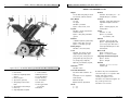
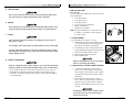
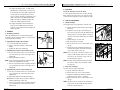
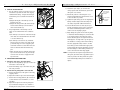
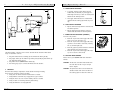
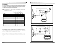
Quickie S-646
Integrated C.G. Tilt
User
SUPPLIER:
THIS MANUAL MUST BE GIVEN TO THE RIDER
OF THIS WHEELCHAIR.
Manual
RIDER:
BEFORE USING THIS WHEELCHAIR READ THIS
ENTIRE MANUAL AND SAVE FOR FUTURE REFERENCE.
Supplement
®
Instruction
I.
2
Introduction
Note
INTRODUCTION
NOTE– This supplement contains information on the operation and adjustments for the
Integrated C.G.Tilt System of a Quickie S-646 wheelchair ONLY. Please refer to
the Quickie S-646 User Instruction Manual for additional notices, EMI information, warnings, tips for attendants, set-up, adjustment and use information,
operating guide, battery and maintenance information, wiring diagrams, and
warranty information regarding the Quickie S-646.
Sunrise Medical
Customer Service Department
7477 East Dry Creek Parkway
Longmont, Colorado 80503
(303) 218-4500 or (800) 333-4000
II.
Ta b l e
of
Contents
3
I. INTRODUCTION NOTE.............................................................................
2
II. TABLE OF CONTENTS..............................................................................
3
III.YOUR CHAIR AND ITS PARTS......................................................................
4
IV. WARNINGS ...........................................................................................
A. Solid Seat Back .................................................................................
B. Driving.............................................................................................
C. Tilting .............................................................................................
6
6
6
6
V. SET UP, ADJUSTMENT & USE...................................................................
A. Battery Removal ................................................................................
B. Solid Seat Back & Lateral Thoracic Supports ..........................................
C. Headrest ..........................................................................................
D. Foam Back........................................................................................
E. Seat Tilt Adjustments .........................................................................
F. TM40 Single or Dual Switch Actuator Controller......................................
G. Articulating Ventilator Tray .................................................................
H. TM40 Single or Dual Switch Actuator Controller......................................
I. Check Out.........................................................................................
7
7
7
8
9
9
10
10
12
12
VI. OPERATING GUIDE ................................................................................
A. Toggle Switch Activation ....................................................................
B. Single Switch Activation.....................................................................
C. Remote Joystick Activation .................................................................
D. Specialty Drive Controls......................................................................
13
13
13
13
13
VII. MAINTENANCE & TROUBLESHOOTING TIPS ............................................... 14
A. Maintenance ..................................................................................... 14
B. Troubleshooting Tips .......................................................................... 14
VIII. WIRING DIAGRAMS ............................................................................... 15
IX. SUNRISE LIMITED WARRANTY................................................................. 16
930576 Rev. A
930576 Rev. A
III.
4
Yo u r
Chair
&
Its
Parts
III.
Yo u r
Chair
&
Its
Parts
5
QUICKIE S-646 INTEGRATED C.G. TILT
16
3
2
9
4
5
6
7
1
10
12
14
11
13
Quickie
S-646
Integrated
1. Push Handle
2. Dual Post, Height-Adjustable
Armrest
3. Remote Joystick
4. Jay Cushion (optional)
5. Swing-Away Footrest Latch
Plate
6. Swing-Away Footrest Hanger
7. Heel Loop
8. Angle Adjustable Footplate
930576 Rev. A
C.G.
9. Solid Seat Back
10. Battery Enclosure
11. 14" Drive Wheels
12. Caster Housing
13. 8" Solid Casters
14. Caster Fork
15. Tilt Toggle Switch
(not shown)
16. Headrest
Tilt
8
Weight
150 lb. With swing-away footrests
and armrests, without batteries
Drive Wheels
14" Mag
Tire types:
Standard - pneumatic
Option - airless insert, solid
Joystick
Standard - remote (right-hand or
left-hand mount)
Option - swing-away retractable
joystick
Batteries
(2 batteries required to operate chair)
Option - GP 24 deep cycle gel,
Option - 22 NF deep cycle gel
Battery Charger
Standard - off board (Lester)
Colors
Standard - blue, black, red, midnight purple, blue velvet, pearl
pink, toxic green, forest green, burgundy, black opal, blue green, yellow, candy purple, candy teal,
Optional: good vibrations, leopard,
graphite
Chair Parts
Standard - black
Seat Frame Dimensions
Seat Frame width: standard - 14"24"
Seat depth: 14"-22" adjustable
Solid seat back
Aluminum seat pan
Optional cushions: Jay Cushions
CG Tilt
3° - 53°
6° - 53°
Backrest
Standard - Non-folding: 15" - 20"
Straight Backpost - standard
Footrest
Standard - Swing-away with angle
adjustable footplates and heel
loops.
Option - elevating legrests, and
multi-position
Casters
Standard - 8" solid
Option - 8" pneumatic
9" pneumatic, solid
Armrests
Standard - dual post flip back
Option - height-adjustable dual
post or single post with desk or
full length waterfall pads or standard armpads
Wheel Locks
Option - Push-to-lock
Option - 6" extension handles
Swing-Away Lateral Thoracic Supports
Option - Curved
Option - Straight
Headrest
Standard - 8" x 5" or 7" x 4.5"
headrest pad
All features may not be available with
some chair setups or in conjunction with
another chair feature. Please
consult your supplier for more
information. Your authorized supplier can
also provide you with more
information on accessories.
930576 Rev. A
I V.
6
Wa r n i n g s
A. SOLID SEAT BACK
Do not use the Solid Seat back to push or lift the wheelchair. Improper use
may cause the back to unexpectedly detach from the wheelchair.
B. DRIVING
You should drive your chair with the tilt at the minimum angle. However, if necessary the chair can be driven with the tilt at an angle of no greater than 15°.
C. TILTING
V.
Set-up,
Adjustment
&
Use
7
TOOLS YOU WILL NEED
Basic Tool Kit:
To set-up, adjust and maintain your chair you will need
the following tools:
• 5/32" Allen wrench
• 3/16" Allen wrench
• 5/16" Allen wrench
• 9/16" box and open-end wrench
• Phillips screwdriver #1
• Standard slot screwdriver
A
NOTE– Setting the wheelchair on a flat surface, such
as a table or a workbench, helps make these
procedures easier.
A. BATTERY REMOVAL
To prevent damage and personal injury, avoid tilting near objects such as
walls, tables or chairs.
To avoid injury, ensure other people, especially children, are clear of the system.
If using a swing-away abductor, be sure not to tilt with the abductor swung
away. Otherwise, the abductor may collide with the tilt actuator when returning the untilted position.
D. CHANGES & ADJUSTMENTS
Never use non-Quickie parts or make changes to your chair unless authorized
by Sunrise. (Doing so will void the warranty and may create a safety hazard.)
1. If you modify or adjust this chair it may increase the risk of fall or tip-over.
2. Modifications unauthorized by Sunrise constitutes remanufacturing of the
wheelchair. This voids the warranty. The rider then assumes all future liability
for the wheelchair.
To remove batteries for transport or service:
1. Unlatch both the right and left battery box rear
cover retaining fasteners (A) by flipping back
both latches and rotating one half turn.
2. Lower battery box rear cover (B) until the cover
is fully extended and supported by the cables (C).
3. Disconnect the battery harness cables.
4. Slide out battery tray using handle.
5. Remove batteries (D).
Batteries may weigh up to 55 lbs. Care must be
taken to avoid injury when lifting.
D
C
A
B
B. SOLID SEAT BACK & LATERAL THORACIC SUPPORTS
1. To adjust the height of the lateral support
mount, loosen the adjustment screw until the
receiver slides freely on the back posts. Tighten
the adjustment screw when the proper height is
determined.
2. Assess and fit the lateral thoracic supports.
Assess client for proper positioning of the lateral thoracic supports. Each support is independent and may be adjusted for your client’s clinical need.
A minimum of 1" (2.5 cm) of clearance should
exist between the top of the lateral support
and the user’s arm pit.
930576 Rev. A
930576 Rev. A
V.
8
Set-up,
Adjustment
&
a) To adjust the height, angle, or width of the
lateral thoracic support pads, loosen the top
bolts and slide to correct width. Tighten bolt
to bolt plate. If more adjustment is necessary, loosen the internally mounted bolts, and
slide in the track to the desired height and
width. The angle is obtained by tilting the
bracket as needed. Tighten the bolts.
b) To adjust the depth of the lateral thoracic
pads, turn the middle bracket so that the
slots are on side. Adjust to desired depth. Retighten the bolts.
Adjustment
&
Use
9
To secure the back foam and cover on the Solid Seat
Back, slide the top edge of the cover over the top lip
of the shell. Press the back in place against the shell.
E. SEAT TILT ADJUSTMENTS
1. Initial Tilt Angle
The upright angle can be adjusted to suit the rider.
a) Operate the tilt system until the seat is tilted
about 30°.
b) Adjust the stop pin (A) to the desired positions. The stop pin lock-nuts (B) determine the
resting position of the seat. When coming to a
rest, the seat should contact both pins simultaneously.
c) Tighten the stop pin lock-nuts.
d) Raise the seat up once again.
e) Remove the access cover on the actuator housing (C).
f) Position the most rearward limit switch (D)
such that the actuator shuts down when the
seat contacts the stop pins (A).
A
NOTE– Do not loosen the screw any more than is necessary to slide the limit switch in its track. If
the screw is over loosened, it may come out
and be difficult to replace.
B
NOTE– Angle, front-to-back distance and left-to-right
position are adjustable in this step.
930576 Rev. A
Set-up,
Secure the foam and cover to the shell.
1. Mounting a headrest.
The Solid Seat Back has a universal headrest plate
mounted to it. Care should be taken to use the proper
screw length when mounting.
c) Use the 3/16" Allen wrench to tighten the three
(3) socket head cap screws on the upper pivot
bracket (B).
4. Adjusting the position of the headrest pad.
a) Use the 5/32" Allen wrench to loosen the three
(3) socket head cap screws at the base of the
headrest (C).
b) Adjust the headrest to the desired position.
Note: Ball and socket can be moved for rotational
headrest adjustment in this step.
c) Use the 5/32" Allen wrench to tighten the three
(3) socket head cap screws at the base of the
headrest (C).
V.
D. FOAM BACK
C. HEADREST
2. Adjusting the height of the headrest.
a) Loosen the hand lever handle (A).
b) Raise or lower the headrest to the desired
height.
c) Tighten the hand lever handle (A).
3. Adjusting the position of the headrest mount.
a) Use the 3/16" Allen wrench to loosen the three
(3) socket head cap screws on the upper pivot
bracket (B).
b) Adjust the headrest position.
Use
C
A
B
C
E
D
NOTE– The limit switch adjustment should not allow
the motor to stall as the seat frame contacts
the stop pins.
2. Drive Lock-out Angle
The drive lock-out angle is adjustable
a) Tilt the seat back at least 30°.
b) Remove the access cover on the actuator.
c) Adjust the middle limit switch (E) until the
desired lock-out position is achieved.
d) Replace the access cover on the actuator housing (C).
NOTE– The drive lock-out should be set such that the
chair cannot be driven with the seat tilted to
an angle of greater than 15°.
930576 Rev. A
V.
10
Set-up,
Adjustment
F. ANTI-TIP CASTER LOCK-OUT
1. The rear anti-tip casters incorporate a lock-out
mechanism to prevent the chair from sagging
rearward when tilting. To adjust the tilt angle
at which they lock-out follow the instructions
below:
a) Adjust the height of the anti-tip lock-out
actuator levers (A).
b) Adjust the cable position (B) at the anti-tip
mount and the anti-tip lock-out actuator
lever mount brackets (C).
2. Proper adjustment of the anti-tip lock-out
levers can be verified when three conditions
exist:
a) The anti-tip lock-out levers under the anti-tip
lower links are retracted when the seat frame
is on the forward stops.
b) The anti-tip lock-out levers (A) located at
the front stop pins (D) do not rotate to the
point that they can not be engaged by the
seat frame forward cross tube when the seat
frame is lowered toward the forward stop
pins.
c) When the seat frame is elevated off the antitip lock-out actuator levers (A), the anti-tip
lock-out levers are free to engage the antitip lower links.
&
Use
D
B
A
C
930576 Rev. A
Set-up,
Adjustment
&
Use
e) Fasten the split clamps (F) such that the
clamps capture both the towel bar (C) and the
swing-arm cross member.
f) Rotate the position of the swing-arm cross
member underneath the towel bar and as close
to the seat back as possible.
g) Tighten the split clamps (F). Do not fully tighten.
Clamps should be tight so that the clamp does
not rotate, except with sufficient hand force.
h) Ensure that the lower four links (G) are positioned such that the upper portion of the links
are slanted rearward beyond the vertical, as
shown in the accompanying figure.
i) Begin tilting the system. If the vent tray binds,
or interferes with the battery box, return the tilt
to an upright position and rotate the clamps
around. Tilt the system once again and observe
what happens. You may need to go through several iterations of clamp position before finding
the most appropriate clamp location. You will
know when you have achieved the appropriate
position when the vent tray articulates just past
the vent battery box when tilting and tucks up
close to the back rest when fully upright.
11
Angle should
be as small as
possible
Links should
be slanted
rearward
NOTE– It is important to keep the angle between the
swing-arm (E) and the vent tray platform (D) as
small as possible. This will prevent the system
from inadvertently binding due to vibration or
impact.
G. ARTICULATING VENTILATOR TRAY
1. Attach the Vent Tray to the S-646 Frame
a) Slip the vent tray battery cage (A) over the rear
frame tube of the S-646 (B).
b) Fasten the battery cage to the frame using the
two bolts provided.
2. Attach Vent Tray Swing-Arm to the Towel Bar.
a) Position the Power C.G. Tilt system in the fully
upright position.
b) Adjust the towel bar (C) to the desired height.
c) Position the vent tray platform (D) such that it
is level with the floor and within 1.5" of the
seat back.
d) Adjust the length of the vent tray swing-arm
(E) such that the swing-arm cross member is
virtually at the same position as the towel bar.
V.
C
F
A
E
D
B
G
930576 Rev. A
V.
12
Set-up,
Adjustment
&
Use
VI.
Operating
Guide
13
A. TOGGLE SWITCH ACTIVATION
E
A
B
D
Stereo Jack
F
H
G
QTRONIX Power Module
H. TM40 SINGLE OR DUAL SWITCH ACTUATOR CONTROLLER
The TM40 actuator controller can be used to activate the tilt mechanism with either
single or dual switch controls.
1. To operate, pull the toggle switch (A) back
toward rider (to tilt back) or push toggle forward away from rider (to return to neutral) until
tilted into the desired position.
2. The toggle switch will return to neutral when
released and the seating system will stop moving.
A
B. SINGLE SWITCH ACTIVATION
1. Depress and hold single switch to tilt back into
the desired position.
2. Depress and hold single switch to return to
neutral until tilted into the desired position.
C. REMOTE JOYSTICK ACTIVATION (OPTIONAL)
From the “off” position
1. Push the on/off mode select toggle switch (A)
down once to turn the chair “on”.
2. Push the on/off mode select toggle switch (A)
up twice to move index to tilt mode (noted by
two (2) actuator lights (B).
3. Push the joystick (C) either forward or backward
until tilted into the desired position.
4. Push the on/off mode select toggle switch (A)
up once to return to drive mode.
C
B
A
D. SPECIALTY DRIVE CONTROLS
1. Plug limit switch harness assembly (A) into TM40 limit switch jack (B).
2. Plug single switch (C) into TM40 single switch jack (D) OR plug dual switch (E)
into TM40 dual switch jack (F).
3. Plug TM40 into the QTRONIX Power Module (G).
4. Use mating plugs (H) to connect the TM40 to the tilt actuator.
I. CHECK-OUT
Once the tilt assembly is adjusted, it should actuate smoothly and easily.
All accessories should also perform smoothly.
1. Verify seat can achieve full tilt and will return to neutral.
2. Verify that the seat frame stops engage the stop pin cushions.
3. Verify the motor cuts out once the neutral position is reached.
4. Verify no debris is interfering with the glide bearings.
5. Verify all hardware is securely tightened.
930576 Rev. A
Please refer to your QTRONIX USCM User Instruction
Manual
CAUTION– The tilt lock-out feature will activate and
the chair will not tilt on slopes steeper
than 6 degrees.
CAUTION– The power base drive lock-out feature will
activate and the chair cannot be driven if
the seating system is tilted more than 15°.
930576 Rev. A
VII.
14
Maintenance
&
Tr o u b l e s h o o t i n g
VIII.
Wiring
Diagrams
15
TM40 Actuator Controller (Independent Switch Control)
A. MAINTENANCE
You should check the items on this chart at the indicated intervals. If any of the items
are loose, worn, bent or distorted, immediately have them checked and/or repaired by
your authorized Sunrise supplier. Frequent maintenance
and servicing will improve performance and extend wheelchair life.
NOTE– Check weekly, and use a clean, dry cloth or compressed air as needed to keep
glide bearings free of debris.
An
al
ly
y
ly
rly
th
te
nu
ar
on
kl
✓
Glide bearings free of debris
✓
Check tires for proper inflation level
✓
Check batteries for proper electrolyte level (wet cell only)
✓
Check plugs and connectors for proper connections
Qu
M
ily
Charge Batteries
ee
W
Da
CHECK...
✓
Check all moving parts for wear
✓
Inspect all nuts, bolts and fasteners for looseness or wear
✓
Inspect upholstery for wear
✓
Remove and inspect motor brushes
✓
Servicing by authorized Supplier
ALM Actuator Controller (Integrated Control)
✓
B. TROUBLESHOOTING TIPS
If you should notice your C.G. Tilt system binding up, not running in a smooth fashion, or emitting an unusual noise during use, a foreign matter may have come into
contact with the glide bearings. If this occurs, use a clean, dry cloth or compressed air
to clear or, if needed, please see your authorized Sunrise supplier.
If your tilt system will not function, check to ensure the tilt lock out sensor is seated
properly in its mount. The wires should lead out of the sensor toward the front of the
chair.
Power Module
930576 Rev. A
930576 Rev. A
16
IX.
Sunrise
Limited
Wa r r a n t y
FOR THREE (3) YEARS:
We warrant the C.G. power tilt seating system seat frame, sub-base frame, actuator and
structural components of this wheelchair against defects in materials and workmanship
for three (3) years from the date of first consumer purchase.
FOR TWO (2) YEARS:
We warrant the ALM (Actuator Lights Module) actuator controller for two (2) years
from the date of first consumer purchase.
FOR ONE (1) YEAR:
We warrant other electronic components such as the single switch actuator controller
for one (1) year from the date of the first consumer purchase.
ADDITIONAL WARRANTY:
We warrant all other original components (such as upholstery, plastic, rubber parts and
painted surfaces) for three (3) months from the date of first consumer purchase.
Sunrise Medical
7477 East Dry Creek Parkway
Longmont, Colorado • 80503 USA
(800) 333-4000
In Canada (800) 263-3390
© 2002, Sunrise Medical 8.02
930576 Rev A