1
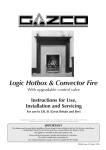
Logic Hotbox & Convector Fire
With upgradable control valve
Instructions for Use, Installation and
Servicing
For use in GB, IE (Great Britain and Eire)
This appliance has been certified for use in countries other than those stated. To install this appliance in these countries, it is essential to obtain the
translated instructions and in some cases the appliance will require modification. Contact Gazco for further information.
IMPORTANT
The chimney must be swept before installation. Do not attempt to burn rubbish on this fire. This fire has a naked flame.
A suitable guard should be used for the protection of young children, the elderly or infirm.
This appliance is intended for decorative purposes only.
Please read these instructions carefully and keep them in a safe place.
They will be needed when servicing the fire.
The commissioning sheet on page 3 must be completed by the Installer.
PR0696 Issue 3 (January 2008)
Covering the following models
Hotbox
8306PBUC
P80306PBUC
8306MCUC
P8306MCUC
Convector
8308PBUC
P8308PBUC
8308MCUC
P8308MCUC
CONTENTS
PAGE
Appliance commissioning checklist
3
user instructions
4
instaLlation Instructions
8
Technical Specifications
8
Site Requirements
10
Installation
12
Commissioning
17
Servicing Instructions
18
Servicing Requirements
18
Fault Finding
19
How to replace parts
21
Basic spare parts list
23
Service Records
24
2
APPLIANCE COMMISSIONING CHECKLIST
IMPORTaNT NOTICE
Explain the operation of the appliance to the end user, hand the completed instructions to them for safe keeping,
as the information will be required when making any guaranteed claims.
FLUE CHECK
Pass
1.
Flue is correct for appliance
2.
Flue flow test
3.
Spillage test
Fail
GAS CHECK
1.
Gas soundness & let by test
2.
Standing pressure test
mb
3.
Appliance working pressure (on High Setting)
mb
NB All other gas appliances must be operating on full
4.
Gas rate
5.
Does ventilation meet appliance requirements
6.
Have controls been upgraded (Upgradeable models only)
m3/h
8455 Standard
YES
NO
DEALER AND INSTALLER INFORMATION
Dealer . . . . . . . . . . . . . . . . . . . . . . . . . . . . . . . . . . . . . . . . . . . . . . . . . . . . . . . . . . . . . . . . . . . . . Installation Company . . . . . . . . . . . . . . . . . . . . . . . . . . . . . . . . . . . . . . . . . . . . . . . . .
. . . . . . . . . . . . . . . . . . . . . . . . . . . . . . . . . . . . . . . . . . . . . . . . . . . . . . . . . . . . . . . . . . . . . . . . . . . . . . . ................................................................................
. . . . . . . . . . . . . . . . . . . . . . . . . . . . . . . . . . . . . . . . . . . . . . . . . . . . . . . . . . . . . . . . . . . . . . . . . . . . . . . ................................................................................
Contact No.. . . . . . . . . . . . . . . . . . . . . . . . . . . . . . . . . . . . . . . . . . . . . . . . . . . . . . . . . . . . . . Engineer . . . . . . . . . . . . . . . . . . . . . . . . . . . . . . . . . . . . . . . . . . . . . . . . . . . . . . . . . . . . . . . . . . . Date of Purchase. . . . . . . . . . . . . . . . . . . . . . . . . . . . . . . . . . . . . . . . . . . . . . . . . . . . . . . Contact No.. . . . . . . . . . . . . . . . . . . . . . . . . . . . . . . . . . . . . . . . . . . . . . . . . . . . . . . . . . . . . . . Model No.. . . . . . . . . . . . . . . . . . . . . . . . . . . . . . . . . . . . . . . . . . . . . . . . . . . . . . . . . . . . . . . . Corgi Reg No.. . . . . . . . . . . . . . . . . . . . . . . . . . . . . . . . . . . . . . . . . . . . . . . . . . . . . . . . . . . . Serial No.. . . . . . . . . . . . . . . . . . . . . . . . . . . . . . . . . . . . . . . . . . . . . . . . . . . . . . . . . . . . . . . . . Date of Installation . . . . . . . . . . . . . . . . . . . . . . . . . . . . . . . . . . . . . . . . . . . . . . . . . . . . Gas Type . . . . . . . . . . . . . . . . . . . . . . . . . . . . . . . . . . . . . . . . . . . . . . . . . . . . . . . . . . . . . . . . . 3
USER INSTRUCTIONS
1. general
2.8 Turn the right hand control to point to main burner ( ). The
appliance can now be controlled using the left hand control
knob.
1.1 Installation and servicing must only be carried out by a
competent person.
1.2 In all correspondence, please quote the appliance type and
serial number, which can be found on the data badge
adjacent to the control knob.
2.9 Turn the left hand control knob to point to low fire ( ), the
main burner will light on low. The burner can now be
controlled between low and high settings. Turn the control
knob anti clockwise increase the flame height and clockwise to decrease the flame height.
1.3 Ensure that curtains are not positioned above the fire, and
that there is a 300mm minimum clearance between the sides
of the fire and any curtains.
THE YELLOW FLAMES WILL APPEAR WHEN THE FIRE HAS
GAINED SUFFICIENT HEAT - TYPICALLY 10 TO 20 MINUTES.
1.4 This product is guaranteed for 12 months from the date of
installation, as set out in the terms and conditions of sale
between Gazco and your local Gazco dealer. Please consult
with your local Gazco dealer if you have any questions. In all
correspondence always quote the Model Number and
Serial Number.
3. TURNING THE FIRE OFF
3.1 To turn the fire off, locate the control valve, turn the left-
hand control knob until it points to off ( ). The main burner will go out leaving the pilot burning.
1.5 Parts of this appliance become hot during normal use. It is
therefore recommended that a suitable fire guard be used for
protection of young children and the infirm.
3.2 To turn the pilot off, locate the control valve, turn the right
hand control knob until it points to off ( ), the pilot will
go out.
2. LIGHTING THE FIRE
4. LIGHTING THE FIRE WITH A MATCH
2.1 Locate the control valve on the appliance. There are two
control knobs on the valve, the right hand knob controls the
pilot ignition and the left hand knob controls the main burner.
If the pilot does not ignite as described in Section 2,
please consult your GAZCO dealer to rectify the problem.
However, the appliance may be lit as a temporary measure
using the following procedure:
2.2 If your appliance has already been upgraded to battery
remote control, please refer to the instructions provided with
the upgrade to operate the remote control. The following
instructions will work for either situation.
4.1 Press in the right hand control knob and rotate it anticlockwise until a click is heard (keep pressing in) and the
knob is pointing to pilot ( ), apply a lighted match to the
pilot hood, see diagram 2.
1
2
AR0914
2.3 Ensure that the left-hand control knob is pointing to off
.
2.4 Ensure that the right hand control knob is pointing to off
.
AR1164
2.5 Press in the right hand control knob and rotate it anti-clockwise
until a click is heard (keep pressing in) and the knob is pointing
to pilot ( ). The pilot should now light. If the pilot has not
lit,
repeat the procedure until it does.
4.2 When the pilot is alight, extinguish the match and continue
to depress for 5 to 10 seconds.
4.3 The fire may now be controlled as previously described.
2.6 Keep the control knob pressed for 10 seconds and then
release it, the pilot should stay alight. If the pilot goes out,
repeat the procedures until it does.
5. UPGRADING YOUR FIRE
2.7 If the pilot will not light after repeated attempts, contact the
retailer or installer from whom the appliance was purchased.
5.1 Your fire is fitted with a control valve that can easily be
upgraded to battery powered remote control. This upgrade
4
USER INSTRUCTIONS
can be fitted by anyone capable of simple DIY jobs and
requires no special training. This upgrade can be obtained
through your local Gazco stockist.
4
5.2 STANDARD REMOTE CONTROL This remote control can
control the fire after the pilot has been lit. It can turn the
main burner on and regulate it from low through to high and
back again. It can turn the main burner off leaving the pilot
burning GAZCO PART NUMBER 8455.
AR1159
6. CLEANING THE FIRE
7.3 Place the rear panel against the rear of the box and slide
the side panels on either side of the flame baffle. Ensure they
locate in the brackets at the top of the firebox. DO NOT
SLIDE THEM ALL THE WAY BACK. See diagram 5.
6.1 Remove the ceramic coals or pebbles and place on a dry,
clean surface. Remove the fuel bed and the burner cover
gasket.
6.2 Clean the burner and tray assembly using a vacuum cleaner
with soft brush attachment, ensure all debris is removed from
the burner ports.
5
6.3 Replace the ceramics by referring to section 7.
7. ARRANGEMENT OF FUEL BED
COMPONENTS
NOTE: CERAMIC PARTS ARE FRAGILE. THE SIDE AND
REAR PANELS ARE REVERSIBLE. ONE SIDE IS PLAIN, THE
OTHER SIDE IS REEDED. ASK THE CUSTOMER WHICH
SIDE IS PREFERRED AT THIS STAGE.
AR1161
7.4 Locate the top panel on top of the rear and side panels.
Finally push the sides fully towards the rear panel. This will
retain the top panel. See diagram 6.
ONLY USE THE CORRECT TYPE AND QUANTITY OF
CERAMIC COMPONENTS. POINTS 7.1 TO 7.5 ARE COMMON TO ALL FUEL TYPES AND LAYOUTS.
6
7.1 Position the burner cover gasket on the burner skin ensuring
the holes align with the ports. Take care as the front
left-hand hole is offset compared to the others.
See diagram 3, arrow A.
3
AR1162
7.5 Place the front coal centrally in the channel at the front of
the tray. See diagram 7. The relationship between the front
coal and flame baffle is shown in diagram 7.
AR1175
7
7.2 Position the flame baffle centrally on the tray and ensure the
stepped lower edge engages against the rear edge of the
burner skin. See diagram 4.
AR1163
5
AR1160
USER INSTRUCTIONS
COAL LAYOUT
10
NOTE: THERE ARE TWO LARGE COALS IN A SEPARATE BAG INSIDE THE MAIN BAG FOR USE WITH A CURVED FRONT (SUCH AS THE HOLYROOD AND
RICHMOND) AND NOT FOR A FLAT FRONTED FRAME.
A) FRONT ROW COAL LAYOUT USING FLAT FIRE FRONTS
7.6
This first row marks the only difference in coal layout between the flat fronts and curved fronts. Place one large coal centrally on the front coal resting against the frame. Then place three small coals either side.
See diagram 8.
AR1167
7.9
8
Place one small coal either side on top of the flame baffle in
each rear corner. Then place two large coals in between the
two small coals. These coals should touch the rear panel.
See diagram 11.
11
AR1166
B) FRONT ROW COAL LAYOUT USING CURVED FIRE
FRONTS
AR1168
7.7 Place three large coals resting on top of the front coal and
against the front of the frame, then place two small coals
either side of the large ones. See diagram 9
7.10
Finally place five large coals between the second and rear
row of coals. See diagram 12.
12
9
AR1169
AR1165
7.11 It is essential that gaps are left between the coals to maximise
the performance of the appliance.
C) COAL LAYOUT CONTINUED FROM FRONT ROW
7.8 Place four large coals behind the first row and one small
coal either end resting up against the side panels.
See diagram 10
PEBBLE LAYOUT - CURVED AND FLAT FRONTS
7.12 ALL THE PEBBLES HAVE AN ID NUMBERS ON THE
UNDERSIDE. ENSURE THE PEBBLES ARE PLACED ONLY
IN THEIR CORRECT POSITIONS.
7.13 Place the first row of pebbles on top of the front coal resting
against the frame front. All the numbers must be placed
face down so they cannot be seen. See diagram 13.
6
USER INSTRUCTIONS
13
8. OXYGEN DEPLETION SENSOR
8.1
AR1171
The appliance is fitted with an oxygen sensitive pilot system
which acts to cut off the gas supply to the fire should the
oxygen in the room fall below its normal level. If the fire is
turned off by this device, it usually indicates that there is a
problem with the flue system, and this should be inspected
by a qualified engineer. Do not attempt to use the fire
until an engineer says it is safe to do so.
This device is not a substitute for an independently
mounted carbon monoxide detector.
7.14 Working from the outer edges, place the second
row of pebbles against the rear of the first row. Note the
orientation of each pebble, as this is important to the
performance of the fire. See diagram 14.
9. FLAME FAILURE DEVICE
14
9.1
This is a safety feature incorporated in all GAZCO fires
which automatically switches off the gas supply if the pilot
light goes out and fails to heat the thermocouple.
10. ‘RUNNING IN’
10.1 The surface coating on the coals used in your GAZCO fire
will ‘burn off’ during the first few hours of use, producing a
harmless and temporary odour. This will disappear after a
short period of use. If the odour persists, ask your installer
for advice.
AR1172
7.15 Place the rear row of pebbles on top of the flame baffle,
these must touch the rear panel. See diagram 15.
11. SERVICING
15
11.1 This fire must be serviced every 12 months by a qualified
Gas Engineer. In all correspondence, always quote the
appliance type and serial number, which may be found on
the data badge located on a chain beneath the control valve.
12. VENTILATION
AR1173
12.1 Any purpose provided ventilation should be checked
periodically to ensure that it is free from obstruction.
7.16 Place the remaining five pebbles between the second and
rear rows. See diagram 16.
13. INSTALLATION DETAILS
16
13.1 To assist in any future correspondence, your installer should
have completed this commissioning sheet, this records, the
essential installation details of the appliance. In all
correspondence always quote the Model Number and
Serial Number.
6
5
4
5
2
AR1174
7
INSTALLATION INSTRUCTIONS
TECHNICAL SPECIFICATION
Covering the following models
GAS CATEGORY
Hotbox
8306PBUC
P80306PBUC
8306MCUC
P8306MCUC
Convector
8308PBUC
P8308PBUC
8308MCUC
P8308MCUC
I2H
Natural
Butane
Propane
G20
G30
G31
20mb
29mb
37mb
High
6.7
6.7
6.7
Low
3.0
3.0
3.0
High
0.64
0.192
0.252
Low
0.29
0.086
0.113
Gas Type
Working Pressure
Gross Input kW
Gas Rate m3/hr
Nox Class
I3+
1
1
Injector Size
400
180
Aeration Size
6 x 15
6 x 15 Rear
23 x 15 Front
Min flue size
5" diameter
Min flue size - pre cast
90mm x 183mm (16,500mm2 min)
Min flue specification
T260 / N2 / 0 / D / 1
Gas Inlet
8mm
Weight (Gross
19Kg
APPLICABLE FRONTS
FRONT
HOTBOX
CONVECTOR
8251MA, 8251IR, 8251GP
8251MA, 8251IR, 8251GP
EVOLUTION
8255MB, 8255BS
8257MB, 8257BS
HOLYROOD
8391
8397
8150
8391
8397
8150
8249BS
8249BS
8253MA, 8253IR
8253MA, 8253IR
N/A
8678
8382, 8385
8388, 8153
8382, 8385
8388, 8153
VICTORIAN CONVECTOR
N/A
4262, 4263
ART NOUVEAU CONVECTOR
N/A
4264, 4265
COMBINATION CONVECTOR
N/A
4362. 4363
DIMENSION
8681MB
8681MB
ARTS FRONT
8288MB, 8288HP, 8288P, 8288PBR
8288MB, 8288HP, 8288P, 8288PBR
ARTS FRAME
8284MB, 8284PBR, 8284P, 8284BS
8284MB, 8284PBR, 8284P, 8284BS
DESIGNIO
INFINITI
PROGRESS
RICHMOND
SPANISH
8
INSTALLATION INSTRUCTIONS
TECHNICAL SPECIFICATION
1
190
125
190
125
OVERALL EXTERNAL DIMENSIONS
Convector
Hotbox
550
372
550
372
SIDE VIEW
AR1179
2
50
50
125
125
MINIMUM DEBRIS COLLECTION
SPACE REQUIREMENTS(EXISTING MASONRY CHIMNEYS ONLY)
Convector
3
404
186
OVERALL EXTERNAL
DIMENSIONS
PLAN VIEW
483
AR1206
9
Hotbox
AR1178
INSTALLATION INSTRUCTIONS
SITE REQUIREMENTS
The appliance can also be fitted into a metal flue box with a
5” (125mm) diameter flexible liner. In this installation a 1”
(25mm) rebated fire surround must be used. Refer to
diagram 2 for dimensions.
1. FLUE AND CHIMNEY REQUIREMENTS
1.1 The chimney or flue system must comply with the rules in
force, and must be a minimum of 125mm (5”) in diameter.
Pre cast flues must conform to BS1289: 1986. The cross
sectional area of the flue must be 16500 mm2 with a
minimum dimension of 90mm.
Class 1 flues. Chimneys over 9” x 9” must be lined.
A flue restrictor is provided with the Logic convector. This
must be fitted when the flue is 9” x 9” or when the flue pull
is excessive. This is fitted from inside the appliance across the
outlet at the top of the convector box with two screws
provided.
*When fitting the appliance to a pre cast flue, the total
minimum depth of fire opening necessary is (D) 215mm. This
allows a 25mm space behind the appliance for debris,
required on this type of flue system. This is achieved either by
using = (A) a 115mm deep starter block + (B) a 25mm
plasterboard and sealed space + (C) 75mm Gazco space
(part number 8315) with a marble slip or similar, inserted
behind the spacer front flange, see diagram 1.
1.2 The minimum effective height of the flue or chimney must
be 3 m (10ft).
1.3 The chimney or flue must be free from any obstruction.
Any damper plates should be removed or secured in the
fully open position, and no restrictor plates should be fitted.
Or the total depth can be achieved by using a deeper starter
block, remedial building work to the front of the fireplace
opening, and a marble slip or similar, or a combination of this.
1.4 The chimney should be swept immediately prior to the
installation of the appliance - unless it can be seen to be
clean and unobstructed throughout its entire length.
NEVER PLASTER DIRECT TO THE FACE OF A PRECAST
FLUE. USE ADHESIVE TO FIX THE PLASTERBOARD TO THE
FACE OF THE FLUE AND FINALLY SKIM THE
PLASTERBOARD.
1.5 Ensure that there is a smooth taper transition from the
fireplace opening into the chimney or flue.
1.6 The flue pull should be checked prior to installation of the
appliance. Apply a smoke pellet to the flue or chimney
opening and ensure that the smoke is drawn into the
opening. If there is not a definite flow, preheat the chimney
for a few minutes and re-test the flow.
1
A = Minimum precast flue starter block depth (115mm).
B = Plasterboard and adhesive seal all around fire opening.
IF THERE IS STILL NO DEFINITE FLOW, THE CHIMNEY
MAY REQUIRE ATTENTION - SEEK EXPERT ADVICE.
C = Gazco spacer (8315)
D = Minimum total depth including 25mm for debris.
A
2. APPLIANCE LOCATION
2.1
This appliance must stand on a non-combustible hearth
that is at least 12mm thick and 50mm thick at least at the
periphery.
2.2
It must be fitted into a non-combustible opening.
2.3
These appliances must be hearth mounted into a fireplace
opening conforming to National Standards. The minimum
dimensions shall be as shown in diagram 2.
B C
D
Hearth level
AR1217
When fitting the Logic Convector fire and a Stovax Cast Iron
Convector fireplace to a precast letter box flue with a
standard starter block, the 8315 spacer kit will be required,
together with an extra deep 142mm rebate surround.
The Combination Convector breast. Fireplace requires a
75mm stud-work chimney breast.
10
INSTALLATION INSTRUCTIONS
SITE REQUIREMENTS
2
A
4. VENTILATION
B
D
It is important to ensure that any national ventilation
requirements are taken into account during the
installation of this appliance.
C
E
50mm (2")
Flue Type
Dimension
Brick Built
Class 1
Pre Fab Metal
Box
Pre Cast
from 1986
A
410
407
305
B
560
560
560
C
250
200
215
D
300
300
300
E
150
150
4.1 This appliance has a nominal input not exceeding 7.0kw
and therefore does not normally require ant additional
permanent ventilation.
If, however, spillage is detected when commissioning the
appliance, there may be insufficient natural ventilation and
additional ventilation may be required.
For ventilation requirements in the Republic of Ireland, it
will be necessary to refer to the relevant rules in force.
150
AR0184
2.4
Ensure that no naked flame or incandescent part of the fire
bed projects beyond the vertical plane of the fireplace
opening.
2.5
The appliance must not be installed in any room that
contains a bath or shower.
2.6
Ensure clearances to combustible materials - see diagram 3
AIR VENTS MUST NOT BE RESTRICTED.
3
AR0707
3. GAS SUPPLY
3.1 Before installation, ensure that the local distribution
conditions (identification of gas and pressure) and
the adjustment of the appliance are compatible.
3.2 Ensure that the gas supply is capable of delivering the
required amount of gas, and is in accordance with the rules
in force.
3.3 This appliance is supplied complete with a factory fitted
isolation device incorporated into the inlet connection, no
further isolation device is therefore required.
11
INSTALLATION INSTRUCTIONS
INSTALLATION
4.1 Before installation, ensure that the local distribution
conditions (identification of the type of gas and pressure)
and the adjustment of the appliance are compatible. See
table above.
1. UNPACKING
1.1 Remove the appliance from its packaging, and check that it
is complete and undamaged.
1.2
4.2 Ensure that the gas supply is capable of delivering the
required amount of gas, and is in accordance with the rules
in force. Please refer to the technical specification for the
correct working pressure for the gas used.
Put the loose ceramic parts to one side so that they are not
damaged during installation.
2. CONTROL UPGRADE
4.3 Soft copper tubing and soft soldered joints can be used but
must not be closer than 50mm (2”) to the underside of the
burner.
2.1 Your fire is fitted with a control valve that can be easily
upgraded to battery powered remote control. This upgrade
can be fitted by anyone capable of simple DIY jobs and
requires no special training. This upgrade can be obtained
through your local Gazco stockist.
4.4 An isolation device is provided with the appliance.
4.5 All supply gas pipes must be purged of any debris that may
have entered, prior to connection to the appliance.
2.2 STANDARD REMOTE CONTROL This remote control can
control the fire after the pilot has been lit. It can turn the
main burner on and regulate it from low through to high and
back again. It can turn the main burner off leaving the pilot
burning. GAZCO PART NUMBER 8455.
5. PREPARING THE APPLIANCE
5.1 Remove the 6 burner retaining screws and withdraw the
burner unit from its location. See diagram 1, arrows B
1
3. SAFETY PRECAUTIONS
3.1 This appliance must be installed in accordance with the rules
in force, and used only in a sufficiently ventilated space.
Please read all instructions before installation and use of this
appliance.
3.2 These instructions must be left intact with the user.
3.3 Do not attempt to burn rubbish on this appliance.
AR1175
3.4 In your own interest, and those of safety, this appliance must
be installed by a competent person in accordance with local
and national codes of practice. Failure to install the appliance
correctly could lead to prosecution.
5.2 Decide on the retention method. If cable fixings are to be
used, remove the two knockout holes on the rear of the
box, using a sharp hammer blow. See diagram 2.
3.5 Keep all plastic bags away from young children.
2
4. INSTALLATION OF THE GAS SUPPLY
NATURAL GAS @ 20mbar
8306MCUC 8306PCUC
8308MCUC 8308PBUC
BUTANE @ 29mbar
PROPANE @ 37mbar
P8306MCUC
P8308MCUC
P8308MCUC
P8308PBUC
AR1154
TO CHANGE FROM ONE GAS TYPE TO ANOTHER A
COMPLETE ENGINE ASSEMBLY WILL BE REQUIRED.
SEE SECTION 8 SERVICING INSTRUCTIONS.
5.3 Remove the backing from the self-adhesive silicone sealing
strip and apply to the rear flange of the firebox ensuring that
it is positioned as close to the outer edge as is practically
possible. See diagram 3.
12
INSTALLATION INSTRUCTIONS
INSTALLATION
5
3
Convector
Hotbox
AR1154
5.4
AR1156
Gas pipe entry must come through the right hand side of
the box. The rubber seal must be cut using a sharp knife to
allow the isolating elbow to pass through it. Ensure the
rubber is not damaged when doing this.
A means of isolation is provided with the appliance. This
must be fitted to the supply pipe prior to installing the
firebox.
6.4
Pass the cables vertically through the 2 sets of eyebolts and
thread the ends through the holes in the lower back of the
firebox. Pass the gas supply pipe through the hole in the
rubber seal (refer to section 5.2) and push the appliance into
place.
6.5
Thread the cables through the tensioner bolts and push the
threaded portions through the holes in the firebox so that
the lock nut sits against the back wall (ensure that the nut is
screwed fully up to the head of the tensioner to allow
maximum adjustment).
6.6
Slide the locking nipples onto the cables, pull the cables taut
and tighten the locking screw. Adjust the lock nuts using a
10mm spanner until the silicone sealing strip forms a tight
seal between the fireplace opening and the firebox flange.
See diagram 6.
6.INSTALLATION OF THE APPLIANCE
6.1
Ensure that the fireplace opening is in compliance with the
requirements of section 2 Site Requirements then proceed
as follows:
A) CABLE RETENTION METHOD
6.2
Mark the position of the 4 fixing holes on the rear of the
fireplace opening and drill the holes using a No. 12 masonry
drill bit. Insert the 4 fibre rawl plugs and screw the eyebolts
in as far as possible leaving the eye horizontal. See diagram 4.
4
AR1155
6
75 75
465
328
75 75
24
48
AR1157
Hotbox
AR1204
6.3
Convector
6.7 Coil up the surplus cable and locate in the back of the
fire box.
AR1205
NEVER SHORTEN THE CABLES, THEY WILL BE REQUIRED
WHEN SERVICING THE APPLIANCE.
Pass the 2 cables through the holes in the bracket on the
back of the firebox and pull taut so that the stop ends sit
tightly against the top of the bracket. See diagram 5.
13
INSTALLATION INSTRUCTIONS
INSTALLATION
B) SCREW FIXING METHOD
7. ARRANGEMENT OF FUEL BED
COMPONENTS
6.8 Alternatively, this appliance can be secured back to the
fire place opening using the screws and rawl plugs provided.
Place the firebox centrally in the opening and mark the
positions of the 4 fixing holes. Drill the holes and insert the 4
rawl plugs. See diagram 7.
NOTE: CERAMIC PARTS ARE FRAGILE. THE SIDE AND
REAR PANELS ARE REVERSIBLE. ONE SIDE IS PLAIN, THE
OTHER SIDE IS REEDED. ASK THE CUSTOMER WHICH
SIDE IS PREFERRED AT THIS STAGE.
7
ONLY USE THE CORRECT TYPE AND QUANTITY OF
CERAMIC COMPONENTS. POINTS 7.1 TO 7.5 ARE COMMON TO ALL FUEL TYPES AND LAYOUTS.
7.1 Position the burner cover gasket on the burner skin ensuring
the holes align with the ports. Take care as the front
left-hand hole is offset compared to the others.
See diagram 9, arrow A.
9
AR1158
6.9 Offer the firebox into the opening and ensure that the gas
supply pipe passes through the rubber seal.
6.10 Refit the burner assembly and secure the 6 pozidriv screws.
Connect the gas supply to the inlet connection on the
burner unit and tighten. It may be necessary to support the
inlet connection with another spanner whilst tightening this
joint. See diagram 8.
AR1175
8
7.2 Position the flame baffle centrally on the tray and ensure the
stepped lower edge engages against the rear edge of the
burner skin. See diagram 10.
10
AR1175
6.11 Turn on the gas supply to the appliance and check for leaks.
Light the fire and check all joints on the appliance for leaks.
6.12 Remove the sealing screw from the inlet connection and
connect a suitable “U” gauge manometer. Light the fire and
turn to the maximum position, refer to the data badge and
ensure that the running pressure is correct. If the pressure
varies significantly from that on the data badge, this may
indicate a supply problem and will require immediate
attention.
AR1159
6.13 Turn the appliance off, disconnect the “U” gauge and
replace the sealing screw. Relight the appliance and check
the sealing screw for leaks.
14
INSTALLATION INSTRUCTIONS
INSTALLATION
RICHMOND) AND NOT FOR A FLAT FRONTED FRAME.
FRONT ROW COAL LAYOUT USING FLAT FIRE FRONTS
7.3 Place the rear panel against the rear of the box and slide
the side panels on either side of the flame baffle. Ensure they
locate in the brackets at the top of the firebox. DO NOT
SLIDE THEM ALL THE WAY BACK. See diagram 11.
7.6 The front row is the only difference in coal layout. Place one
large coal centrally on the front coal resting against
the frame. Then place three small coals either side.
See diagram 14.
11
14
AR1161
7.4 Locate the top panel on top of the rear and side panels.
Finally push the sides fully towards the rear panel. This will
retain the top panel. See diagram 12.
AR1166
FRONT ROW COAL LAYOUT USING CURVED FIRE
FRONTS.
12
7.7 Place three large coals resting on top of the front coal and
against the front of the frame, then place two small coals
either side of the large ones. See diagram 15.
15
AR1162
7.5 Place the front coal centrally in the channel at the front of
the tray. See diagram 13. The relationship between the front
coal and flame baffle is shown in diagram 13.
AR1165
COAL LAYOUT CONTINUED FROM FRONT ROW
7.8 Place four large coals behind the first row and one small
coal either end resting up against the side panels.
See diagram 16.
13
16
AR1163
AR1160
COAL LAYOUT
AR1167
NOTE: THERE ARE TWO LARGE COALS IN A SEPARATE BAG INSIDE THE MAIN BAG FOR USE WITH A CURVED FRONT (SUCH AS THE HOLYROOD AND
7.9
15
Place one small coal either side on top of the flame baffle in
each rear corner. Then place two large coals in between the
INSTALLATION INSTRUCTIONS
INSTALLATION
two small coals. These coals should touch the rear panel.
See diagram 17.
orientation of each pebble, as this is important to the
performance of the fire. See diagram 20.
17
20
AR1168
AR1172
7.15 Place the rear row of pebbles on top of the flame baffle,
these must touch the rear panel. See diagram 21.
7.10 Finally place five large coals between the second and rear
row of coals. See diagram 18.
21
18
AR1173
AR1169
7.11 It is essential that gaps are left between the coals to maximise
the performance of the appliance.
7.16 Place the remaining five pebbles between the second and
rear rows. See diagram 22
PEBBLE LAYOUT - CURVED AND FLAT FRONTS
22
7.12 ALL THE PEBBLES HAVE AN ID NUMBER ON THE
UNDERSIDE. ENSURE THE PEBBLES ARE PLACED ONLY
IN THEIR CORRECT POSITIONS.
7.13 Place the first row of pebbles on top of the front coal resting
against the frame front. All the numbers must be placed
face down so they cannot be seen. See diagram 19.
6
19
5
4
5
2
AR1174
AR1171
7.14 Working from the outer edges, place the second
row of pebbles against the rear of the first row. Note the
16
INSTALLATION INSTRUCTIONS
INSTALLATION / COMMISSIONING
11. LIGHTING THE FIRE
1. COMMISSIONING
11.1
Locate the control valve on the appliance. There are two
control knobs on the valve, the right hand knob controls
the pilot ignition and the left hand knob controls the main
burner.
11.2
If your appliance has already been upgraded to battery
remote control, please refer to the instructions provided
with the upgrade to operate the remote control. The
following instructions will work for either situation.
1.1 Close all windows and doors to the room, check all controls,
and allow fire to burn on maximum for 5 minutes. Test for
spillage of flue products using a smoke match. Pass the
lighted smoke match along the top front edge just inside the
opening or canopy. See diagram 1.
1
Hotbox
1
AR0726
AR0914
Convector
11.3 Ensure that the left-hand control knob is pointing to off ( ).
11.4 Ensure that the right hand control knob is pointing to off ( ).
11.5 Press in the right hand control knob and rotate it anticlockwise until a click is heard (keep pressing in) and the
knob is pointing to pilot ( ). The pilot should now light. If the pilot has not lit, repeat the procedure until it does.
11.6 Keep the control knob pressed for 10 seconds and then
release it, the pilot should stay alight. If the pilot goes out,
repeat the procedures until it does.
1.2 If the fire spills, run for a further 10 minutes and re-check. If
the flue restrictor plate has been fitted to the fire this can be
removed to assist flue flow if required. ( Convector only)
11.7 If the pilot will not light after repeated attempts, contact the
retailer or installer from whom the appliance was purchased.
1.3 If there are extractor fans in the room or adjacent rooms, the
spillage test must be repeated with the extractors running on
maximum.
11.8 Turn the right hand control to point to main burner (
).
The
appliance can now be controlled using the left hand control
knob.
IF SPILLAGE PERSISTS, DISCONNECT THE APPLIANCE
AND SEEK EXPERT ADVICE.
For future reference record the installation details on the
commissioning sheet on page 3 of these instructions.
11.9 Turn the left hand control knob to point to low fire (
), the main burner will light on low. The burner can now be
controlled between low and high settings. Turn the control
knob anti-clockwise increase the flame height and clockwise
to decrease the flame height.
THE YELLOW FLAMES WILL APPEAR WHEN THE FIRE HAS
GAINED SUFFICIENT HEAT - TYPICALLY 10 TO 20 MINUTES.
17
SERVICING INSTRUCTIONS
SERVICING
1. SERVICING REQUIREMENTS
This appliance must be serviced at least once a year by a
competent person.
All tests must be serviced by best practice as described by
the current CORGI recommendations.
1.1 Before any tests are undertaken on the appliance, conduct a
gas soundness test for the property to ensure that there are
no gas leaks prior to starting work.
1.2 Before any tests are undertaken on the appliance it is also
recommended to fully check the operation of the appliance.
1.3 Special checks
1.3.1 Clean any lint or fluff from the pilot - pay particular
attention to the aeration hole in the side of the pilot.
1.3.2 Clean away any fluff or lint from under the burner
1.3.3 Check that the spark gap on the pilot is correct.
1.4 Correct any faults found during the initial tests and then
recommission the appliance conducting the usual safety
checks.
1.5 Advise the customer of any remedial action taken.
1.6 As part of the annual service, the space behind the firebox
must be inspected for any debris, which may have fallen
down the chimney.
1.7 Remove the gas fire from the firebox as detailed below.
1.8 Inspect the space behind the firebox for debris and the
condition of the chimney, the flue flow test should be carried
out now. Remove any debris and carry out any necessary
remedial work.
18
NO
19
YES
NO
NO
NO
Has the system got
any air in it?
YES
Is the gas pressure
correct?
YES
Is the gas turned on to
the appliance?
NO
Will the pilot light
with a match?
YES
Is the control being
operated correctly?
See “No Spark”
Chart *
System O.K
There is a blockage in the system, check the inlet test point, the mag
seating, valve and pilot filter
Purge the gas pipes
and retry
Correct and retry.
Check isolation tap
and gas meter, retry.
YES
Consult users book
and retry
Ensure gap between the
electrode and thermocouple
is as Dia. 8 and retry.
If gap is O.K then first
change the ignition lead and
retry.
NO
NO
Does the pilot light?
YES
*
YES
Replace the ODA unit
Is the electrode wire
detached from the piezo
valve?
NO
Remove the electrode lead
from electrode with
insulated pliers hold the tip
3.5mm from the pilot
pipework,is there a spark
when the valve ‘clicks’?
NO
Has ignition lead become
detached or is connection
poor?
YES
Is the gap between electrode
and thermocouple
as in Dia 7?
YES
Operate the valve to
light the pilot, does the
valve ‘click’?
Replace the electrode
lead and retry
YES
YES
NO
NO
Replace the
control valve
Remove the electrode lead
from the piezo. Operate
the valve. Does a spark
jump from the piezo to
the valve body?
Check for defective or
damaged control knob
spindle or cam operation.
Check for the correct
location of piezo
components. Correct and
retry.
Correct and retry
Reset the pilot
burner
Is the valve being
operated correctly?
Consult users
instructions, retry
Ensure there is no debris around the pilot assembly, e.g. coal, soot, etc
which could short the spark, clean the area.
Ensure there is no debris around the pilot assembly, e.g. coal, soot, etc
which could short the spark, clean the area. Check for fluff in the pilot
aeration hole. See diagram 7.
YES
NO SPARK
PILOT WILL NOT LIGHT
Operate the valve.
Is there a spark?
IGNITION FUNCTIONAL CHECK 2
IGNITION FUNCTIONAL CHECK 1
YES
SERVICING INSTRUCTIONS
FAULT FINDING CHARTS
SERVICING INSTRUCTIONS
FAULT FINDING CHARTS
FLAME FAILURE FUNCTIONAL CHECK
PILOT WILL NOT STAY LIT OR FIRE GOES OUT
If the appliance goes out in use continually, this may mean that the
oxygen depletion sensor has been activated. The appliance should not be used
until the cause has been found and rectified.
Ensure there is no debris around the pilot assembly, e.g. coal, soot, etc.
Check for fluff in the pilot aeration hole. See diagram 7.
Light the pilot and keep the control knob pushed in at least
10 seconds before letting go
With the pilot
running is the
gas pressure as
stated on the
data badge?
YES
NO
NO
NO
Is thermocouple
connection good
in back of valve
YES
NO
Run for 60 sec’s.,
turn off, time
interval until mag
unit shuts with a
click. Is this greater
than 7 seconds?
NO
NO
Tighten the
connection and
retry
Replace
ODS unit
YES
Will the pilot
stay lit?
NO
Change the
ODS unit
With the fire
running on full is
the gas at the
pressure stated
on the data badge
Problem is with
the pipe work or
fittings which lead
to the fire. Correct
and retry
Is the pilot
flame of the
correct length?
See diagram 7.
NO
YES
Will the pilot
stay lit?
Change
mag unit
NO
Run for 60 sec’s.,
turn off, time
interval until mag
unit shuts with a
click. Is this greater
than 7 seconds?
YES
SYSTEM O.K
20
YES
SERVICING INSTRUCTIONS
REPLACING PARTS
2.3 To release the right hand side of the control cover insert the
narrow blade screwdriver into the slot shown in diagram 3,
lever it gently and pull from the right hand side at the same
time. The cover will now come off, there is a small
cylindrical metal spacer inside the cover, this must be kept
and replaced on the fixing screw during re-assembly.
1. GENERAL
In order to service any of the following parts on the
appliance, it will be necessary to remove the burner unit
from the firebox. To remove the burner unit proceed as
follows.
1.1 Turn off the gas supply at the isolation device located under
the appliance.
3
1.2 Disconnect the gas supply pipe leaving the isolation device
on the supply pipe and not the appliance.
1.3 Remove the loose coals or pebbles and place on a dry clean
surface.
1.4 Remove the decorative frame, fret and ash cover. There are
two screws securing the frame to the appliance. Refer to
frame instructions.
AR0916
1.5 Remove the front coal, flame baffle and all the ceramic liners.
All these items are very fragile so store them carefully.
2.4 Disconnect the ignition lead from the gas valve and the pilot.
See diagram 4 arrow A.
1.6 Remove the six screws securing the burner unit to the fire
firebox. See diagram 1.
4
1
A
AR1177
AR1175
2.5 Replace with a new ignition lead following the same route as
the old one. Replace the valve cover and the pilot assembly.
1.7 The burner unit can now be removed.
2.6 Check the operation of the new ignition lead.
2. IGNITION LEAD
2.7 Replace the fret.
2.1 Remove the fire. Refer to section 1.
3. piezo
2.2 Undo the single screw that secures the left hand side of the
control cover. See diagram 2.
3.1 The piezo assembly used on this appliance is not serviceable
and is unlikely to fail. If a new piezo is required it will be
necessary to change the gas valve, refer to section 5.
2
4. ods pilot unit
Note: The pilot unit on the appliance is a non serviceable
unit due to the complex nature of its manufacture.
Replacement of the complete unit must be carried out when
one of the following items becomes faulty:
Pilot injector
AR0915
Ignition electrode
Thermocouple
4.1 Remove the fire, refer to section 1.
21
SERVICING INSTRUCTIONS
REPLACING PARTS
4.2 Gently pull the ignition lead off the electrode. See diagram 5
arrow A.
m
8
15
.0
m
4.0mm
5
A
AR0097
AR1176
4.6 After reassembly, check for gas soundness and carry out a
flame failure functional check details in the flow chart,
especially the mag drop out time.
4.3 Remove the two screws securing the pilot assembly. See
diagram 6 arrow B.
6
5. gas valve
5.1 Remove the fire, refer to section 1.
5.2 Disconnect the 2x8mm and 1x4mm gas pipe fittings at the
back of the gas valve and also disconnect the thermocouple,
see diagram 9 arrows B and E.
B
9
AR1176
4.4 Undo the thermocouple connection at the back of the gas
valve and the pilot pipe at the pilot elbow. See diagram 7
arrows B and C.
C
7
B
E
C
AR1177
5.3 Disconnect the injector nut. See diagram 10 arrow D.
B
10
AR1177
4.5 Replace with a new pilot assembly, set the spark gap. See
diagram 8.
D
AR1177
5.4 Undo the two bolts securing the gas valve to the appliance
and remove the valve.
22
SERVICING INSTRUCTIONS
REPLACING PARTS
5.5 Replace in reverse order.
8. changing between gas types
5.6 Check all joints for gas leaks, check operation of the
thermocouple and ignition lead.
The following parts must be changed when converting an
appliance from one gas type to another:
6. mag unit
Burner assembly
NGA8306
LPGAP8306
PR0393L
6.1 Remove the fire, refer to section 1.
Data badge
6.2 Under the thermocouple nut. See diagram 11 arrow B.
Note: The control valve will be set for the particular
appliance and gas type. In all instances, when ordering new
parts, be sure to quote the appliance type and serial number.
6.3 Undo the mag unit retaining nut at the back of the control
valve behind the thermocouple nut.
Use only genuine Gazco replacement parts. Non-standard
components will invalidate the guarantee and may be
dangerous.
11
9. spares part lists
CERAMICS
B
AR1177
6.4 After removing the retaining nut, the mag unit can be tapped
out and a replacement fitted.
6.5 Replace the mag unit retaining nut and tighten. Note - this is
a gas-tight seal.
6.6 Replace the thermocouple and check for gas leaks.
6.7 After reassembly, carry out the flame failure functional check
as detailed in the flow chart, especially the mag unit drop out
time.
7. main injector
7.1 Remove the fire, refer to section 1.
7.2 With the fire removed, undo the injector compression nut
and valve nut (see diagram 12 arrows D and E), pull the pipe
clear of the injector body.
FRONT COAL - BLACK
CE0400
FRONT COAL - GREY
CE0401
FLAME BAFFLE - BLACK
CE0402
FLAME BAFFLE - GREY
CE0403
BURNER COVER GASKET
CE0273
CONVECTOR SIDE LH
CE0408
CONVECTOR SIDE RH
CE0409
CONVECTOR REAR PANEL
CE0410
CONVECTOR TOP PANEL
CE0411
HOTBOX SIDE LH
CE0404
HOTBOX SIDE RH
CE0405
HOTBOX REAR PANEL
CE0406
HOTBOX TOP PANEL
CE0407
COAL SET
CE0412
PEBBLE SET
CE0455
NATURAL GAS PARTS
12
MAIN INJECTOR
IN0007
PILOT ASSEMBLY
PI0036
GAS VALVE
GC0088
LPG PARTS
D
E
MAIN INJECTOR
IN0025
PILOT ASSEMBLY
PI0037
GAS VALVE
GC0088
MISCELLANEOUS
AR1177
IGNITION LEAD
GC0090
7.3 Rotate the injector until it is fully removed.
MAG UNIT
GC0092
7.4 Replace with the correct replacement injector. When
ordering, always state the model, gas type and serial number.
7.5 Reassemble and turn the gas supply on, check for any leaks.
CONTROL COVER
GC0087
UPGRADE KIT
23
8455
SERVICE RECORDS
1st Service
Date of Service:. . . . . . . . . . . . . . . . . . . . . . . . . . . . . . . . . Next Service due:. . . . . . . . . . . . . . . . . . . . . . . . . . . . . . . . Signed:. . . . . . . . . . . . . . . . . . . . . . . . . . . . . . . . . . . . . . . . Dealer’s Stamp
2nd Service
Date of Service:. . . . . . . . . . . . . . . . . . . . . . . . . . . . . . . . . Next Service due: . . . . . . . . . . . . . . . . . . . . . . . . . . . . . . . Signed: . . . . . . . . . . . . . . . . . . . . . . . . . . . . . . . . . . . . . . . Dealer’s Stamp
3rd Service
Date of Service:. . . . . . . . . . . . . . . . . . . . . . . . . . . . . . . . . Next Service due:. . . . . . . . . . . . . . . . . . . . . . . . . . . . . . . . Signed:. . . . . . . . . . . . . . . . . . . . . . . . . . . . . . . . . . . . . . . . Dealer’s Stamp
4th Service
Date of Service:. . . . . . . . . . . . . . . . . . . . . . . . . . . . . . . . . Next Service due: . . . . . . . . . . . . . . . . . . . . . . . . . . . . . . . Signed: . . . . . . . . . . . . . . . . . . . . . . . . . . . . . . . . . . . . . . . Dealer’s Stamp
5th Service
Date of Service:. . . . . . . . . . . . . . . . . . . . . . . . . . . . . . . . . Next Service due:. . . . . . . . . . . . . . . . . . . . . . . . . . . . . . . . Signed:. . . . . . . . . . . . . . . . . . . . . . . . . . . . . . . . . . . . . . . . Dealer’s Stamp
6th Service
Date of Service:. . . . . . . . . . . . . . . . . . . . . . . . . . . . . . . . . Next Service due: . . . . . . . . . . . . . . . . . . . . . . . . . . . . . . . Signed: . . . . . . . . . . . . . . . . . . . . . . . . . . . . . . . . . . . . . . . Dealer’s Stamp
7th Service
Date of Service:. . . . . . . . . . . . . . . . . . . . . . . . . . . . . . . . . Next Service due:. . . . . . . . . . . . . . . . . . . . . . . . . . . . . . . . Signed:. . . . . . . . . . . . . . . . . . . . . . . . . . . . . . . . . . . . . . . . Dealer’s Stamp
8th Service
Date of Service:. . . . . . . . . . . . . . . . . . . . . . . . . . . . . . . . . Next Service due: . . . . . . . . . . . . . . . . . . . . . . . . . . . . . . . Signed: . . . . . . . . . . . . . . . . . . . . . . . . . . . . . . . . . . . . . . . Dealer’s Stamp
9th Service
Date of Service:. . . . . . . . . . . . . . . . . . . . . . . . . . . . . . . . . Next Service due:. . . . . . . . . . . . . . . . . . . . . . . . . . . . . . . . Signed:. . . . . . . . . . . . . . . . . . . . . . . . . . . . . . . . . . . . . . . . Dealer’s Stamp
10th Service
Date of Service:. . . . . . . . . . . . . . . . . . . . . . . . . . . . . . . . . Next Service due: . . . . . . . . . . . . . . . . . . . . . . . . . . . . . . . Signed: . . . . . . . . . . . . . . . . . . . . . . . . . . . . . . . . . . . . . . . Dealer’s Stamp
Gazco Limited, Osprey Road, Sowton Industrial Estate, Exeter, Devon, England EX2 7JG
Tel: (01392) 261999 Fax: (01392) 444148 E-Mail: [email protected]