1
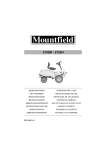
STIGA
DUO LINE
Snow Rise
BRUKSANVISNING SV .... 5
KÄYTTÖOHJEET FI ... 12
BRUGSANVISNING DA . 19
BRUKSANVISNING NO. 26
GEBRAUCHSANWEISUNG DE .. 33
INSTRUCTIONS FOR USE EN .. 40
MODE D’EMPLOI FR ... 47
ISTRUZIONI PER L´USO IT .... 54
INSTRUKCJA OBS£UGI PL ... 61
»HC“P”K÷»fl œOÀ‹«Œ¬¿“EÀfl RU.. 69
NÁVOD K POU®ITÍ CS... 78
HASZNÁLATI UTASÍTÁS HU . 85
NAVODILA ZA UPORABO SL.... 92
8218-2220-70
1
1
2
3
4
6
5
7
8
10
11
9
12
16
13
14
15
2
3
B
A
C
2
5
4
F
D
G
E
7
6
H
H
T
U
8
V
I
A
B
9
3
EN
ENGLISH
1 SYMBOLS
The following symbols appear on the machine. They are
there to remind you of the care and attention required in use.
This is what the symbols mean:
Warning.
2.2 PREPARATIONS
• Check the area to be cleared and remove any loose or
foreign objects.
•
Disengage all controls before starting the engine.
•
Never use the snow thrower unless properly dressed.
Wear footwear that improves your grip on a slippery
surface.
•
Warning – Petrol is highly inflammable.
Read and understand the owner’s manual
before using this machine.
Disconnect the spark plug wire, and
consult technical literature before
performing repairs or maintenance.
Danger - rotating fan.
Danger - rotating auger.
•
Keep hands out of discharge chute.
•
Never, under any circumstances, make adjustments while
the engine is running (unless otherwise specified in the
instructions).
•
Allow the snow thrower to adjust to the outdoor
temperature before using it.
•
Always use protective goggles or a visor during use,
maintenance and service.
Keep hands and feet away from rotating
parts.
Risk of burns.
Keep bystanders at a safe distance from
the machine.
Never point the discharge chute towards
bystanders.
Use hearing protection.
2 SAFETY INSTRUCTIONS
2.1 GENERAL
• Please read through these instructions carefully. Learn all
the controls and the correct use of the machine.
• Never allow children or anyone who is not familiar with
these instructions to use the snow thrower. Local
regulations may impose restrictions as regards the age of
the driver.
• Never use the machine if others, particularly children or
animals, are in the vicinity.
• Remember that the driver is responsible for accidents that
happen to other people or their property.
• Be careful not to trip or fall, especially when reversing
the machine.
• Never use the snow thrower under the influence of
alcohol or medication and if you are tired or ill.
40
a. Always store petrol in containers that are made
especially for this purpose.
b. Only fill or top up with petrol outdoors, and never
smoke when filling or topping up.
c. Fill with petrol before starting the engine. Never
remove the filler cap or fill with petrol while the engine
is running or still warm.
d. Screw the filler cap on tightly and wipe up any spilt
petrol.
Adjust the height of the auger housing to ensure it stays
above gravel paths.
2.3 OPERATION
• Keep hands and feet away from rotating parts. Always
avoid the discharge chute opening.
• Be careful when driving on or crossing gravel paths,
pavements and roads. Be aware of hidden dangers and
traffic.
• Never direct the discharge chute towards a public road or
traffic.
• If the snow thrower hits a foreign object, stop the engine,
disconnect the spark plug cable and carefully inspect the
machine for damage. Repair the damage before using the
machine again.
• If the machine starts vibrating abnormally, stop the
engine and look for the cause. Vibration is normally a
sign of something wrong.
• Stop the engine and disconnect the spark plug cable:
a. If the machine steers away from the driving position.
b. If the auger housing or discharge chute is blocked and
must be cleaned.
c. Before beginning repairs or adjustments.
• Always make sure the rotating parts have stopped and all
the controls are disengaged before cleaning, repairing or
inspection.
• Before leaving the machine unattended, disengage all the
controls, put it into neutral gear, stop the engine and
remove the ignition key.
•
Never run the engine indoors except when taking it in and
EN
ENGLISH
out of its place of storage. In this case ensure the door to
the storage place is open. Exhaust fumes are toxic.
3 ASSEMBLY
•
Never drive across a slope. Move from the top down, and
from the bottom to the top. Be careful when changing
direction on a slope. Avoid steep slopes.
Note: Instructions to the left and right sides start from the
driving position behind the snow thrower.
•
Never operate the machine with insufficient protection or
without the safety devices in place.
•
Existing safety devices must not be disconnected or
disengaged.
•
Do not alter the engine’s regulator setting and do not race
the engine. The possibility of personal injury increases
when the engine is run at high revs.
3.1 CONTENTS - OUTER PACKING
The packing contains:
- One snow thrower
- One adjustment lever
- One gear rod
- One discharge chute
- One set of instructions
- One assembly kit
•
Never use the snow thrower near enclosures, cars,
windowpanes, slopes etc. without properly setting the
discharge chute deflector.
•
Always keep children away from areas to be cleared. Get
another adult to keep the children under supervision.
•
Do not overload the machine by driving it too fast.
•
Take care when reversing. Look behind you before and
during reversing to check for any obstacles.
•
Never point the discharge chute towards bystanders. Do
not allow anyone to stand in front of the machine.
•
Disengage the auger when the snow thrower is to be
transported or is not in use Do not drive too fast on
slippery surfaces when transporting.
•
Only use accessories that are approved by the machine’s
manufacturer.
•
Never drive the snow thrower in bad visibility or without
satisfactory lighting.
•
Always ensure you have a good balance and a tight grip
on the handle.
•
Never use the snow thrower on a roof.
•
Do not touch engine components because they are warm
during use. Risk of burn injuries.
2.4 MAINTENANCE AND STORAGE
• Tighten all nuts and screws so that the machine is in safe
working condition. Check the shear bolts regularly.
•
Always use genuine spare parts. Non-genuine spare parts
can entail a risk of injury, even if they fit the machine.
•
Never store the machine with petrol in the tank in
buildings where the fumes can come into contact with
open flames or sparks.
•
Allow the engine to cool before putting the machine in
store.
•
Before a long storage, check the instructions for
recommendations.
•
Replace damaged warning and instruction stickers.
•
Let the engine run a couple of minutes with the auger
connected after use. This prevents the auger from
freezing solid.
3.2 UNPACKING
1. Remove all loose items from the carton.
2. Cut off the plastic straps holding the adjustment lever and
the gear rod.
3. Cut the four corners of the carton and let the sides fall
down.
4. Unscrew the screws (X) that fasten the shoes to the
bedding. See fig. 1.
5. Roll the snow thrower from the carton.
6. Cut the plastic tape holding the control wires on the
underside of the handle.
3.3 HANDLE, SEE FIG. 2, 3
1. Hook on the auger and drive wires Z-nipples into their
handles.
2. Assemble the handle with the following parts:
A Four Screws
B Two Support plates for the upper screws
C Two Washers for the lower screws
3. Tighten the four screws.
3.4 SNOW DISCHARGE CHUTE, SEE FIG. 4
1. Place the discharge chute (D) on the flange against the
worm gear.
2. Mount the three carriage pieces (E) with two screws each.
3. Tighten properly.
3.5 ADJUSTMENT LEVER, SEE FIG. 5
1. Assemble the eyebolt (F) in the handle.
2. Insert the shaft end into the plastic bushing and adapt the
worm gear to the recesses in the discharge chute.
3. Lock the joint with the locking pin (G).
4. Check the discharge chute by turning it fully in both
directions. The chute should rotate freely.
3.6 GEAR LEVER, SEE FIG. 6
Assemble the gear lever to the gearbox shaft as follows:
1. Set up the machine on the auger housing and set the ger
lever (H) in the first gear forwards. See fig. 6.
2. Assemble the screw (I) through the angle joint and shaft.
Tighten the screw.
3. Tighten the upper screw (T) between the gear lever and
the angle joint.
4. Tighten the lower screw (U) between the gear lever and
the angle joint.
41
EN
ENGLISH
5. Tighten the screw (V) until the gear lever remains in the
gear positions in the panel plate.
6. Set down the machine on its wheels.
3.7 CHECKING THE CONTROL WIRES
The control wires might need adjusting before using the
snow thrower for the first time.
See ADJUSTING THE CONTROL WIRES below.
3.8 TYRE PRESSURE
Check the air pressure in the tyres. See “6.5”.
4 CONTROLS
The motor is equipped with a protection grid. The
motor may never be started without the grid fitted
or with a defect grid.
See fig. 1.
4.1 THROTTLE (16)
Controls the engine’s revs. The throttle has three positions:
1. Full throttle
2. Idling.
4.2 CHOKE (3)
Used when starting a cold engine. The choke has two
positions:
1. The choke is open
4.8 OIL DRAINING PLUG (14)
For draining the old engine oil when changing the oil.
4.9 SPARK PLUG PROTECTION (1)
The protection is easily removable by hand. The spark plug
is located under the protection.
4.10 GEAR LEVER (4)
The machine has 5 forward gears and 2 reverse to regulate
the speed.
The gear stick must not be moved if the driving clutch
lever is depressed.
4.11 CLUTCH LEVER- DRIVING (6)
Engages the wheels when put into gear and the lever
is pushed towards the handle.
Situated on the left side of the handle.
4.12 CLUTCH LEVER- AUGER (7)
Connects the auger and fan when the lever is pushed
down towards the handle.
Situated on the right side of the handle.
4.13 ADJUSTMENT LEVER (5)
Changes the direction of the discharged snow.
1. Turn the lever clockwise – the discharge turns to
the left.
2. Turn the lever anti-clockwise – the discharge turns
to the right.
2. The choke is closed (for cold starting)
4.3 STOP SWITCH (13)
Used to stop the engine. The switch has two positions:
0– The engine stops, engine can not start.
1– The engine can be started, engine running.
4.4 STARTING HANDLE (12)
Manual cord start with rewinding.
4.5
4.6
DIPSTICK (15)
For filling and checking the oil level in the engine.
The dipstick has two level marks:
FULL = maximum oil level
ADD = minimum oil level
FILLER CAP (8)
For filling with petrol.
4.7 FUEL COCK(3)
The fuel cock opens the fuel supply to the carburettor. The
fuel cock shall always be closed when the machine is not in
use.
Downwards - open.
To the right - closed.
42
4.14 SHOES (11)
Used to set the height of the auger housing above the ground.
4.15 WHEEL LOCK
See fig. 7. The left wheel is mounted on the wheel shaft with
the help of a locking pin. The locking pin can be moved to
two positions:
A) Inner position – two-wheel drive.
B) Outer position – one-wheel drive. Simplifies
manoeuvring the machine when turning.
- Used during lighter conditions.
- When storing the machine.
4.16 CHUTE DEFLECTOR (9)
Losen the wing nuts and adjust the chute deflector to a
suitable height.
Low - shorter ejection distance.
High - longer ejection distance.
ENGLISH
5 USING THE SNOW THROWER
5.1 GENERAL
Never start the engine until all the above measures under
ASSEMBLY have been carried out.
Never use the snow thrower without first reading
and understanding the instructions and all the
warning and instruction stickers on the machine.
Always use protective goggles or a visor during
use, maintenance and service.
5.2 BEFORE STARTING
Some snow throwers are delivered without oil in the engine.
Fill the engine with oil before using.
Do not start the engine until filled with oil. The
engine can be seriously damaged without oil.
1. Place the machine on a level floor.
2. Loosen the dipstick and fill with oil up to the FULL mark
See fig. 8.
3. Use good quality oil marked A.P.I service SF, SG or SH.
Use SAE 5W30 - 10W40 oil.
4. The crankcase holds: 0.45 litres.
Always check the oil level before using. The snow thrower
must stand on level ground when checking.
5.3 FILL UP THE PETROL TANK
Always use lead-free petrol. Oil-mixed 2-stroke petrol must
not be used.
NOTE! Bear in mind that ordinary lead-free petrol is
perishable; do not purchase more petrol than can be used
within thirty days.
Environmental petrol can be used, i.e. alkylate petrol. This
type of petrol has a composition that is less harmful for
people and nature.
Petrol is highly inflammable. Always store fuel in
containers that are made especially for this
purpose.
Store the petrol in a cool, well ventilated place –
not in the house. Store the petrol well out of reach
for children.
Only fill or top up with petrol outdoors, and never
smoke when filling or topping up. Fill with fuel
before starting the engine. Never remove the filler
cap or fill with petrol while the engine is running
or still warm.
Do not fill the petrol tank right to the top. After filling, screw
the filler cap on tightly and wipe up any spilt petrol.
5.4
STARTING THE ENGINE, SEE FIG. 1
Do not touch engine components because they are
warm during use and up to 30 minutes after use.
Risk of burn injuries.
Never run the machine indoors. The exhaust
fumes contain carbon monoxide, a very toxic gas.
1. Make sure the driving (6) and auger (7) clutch levers are
disengaged.
2. Set the stop switch (13) in position “1”.
EN
3. Turn the choke (3) to position . Note: A warm engine
does not need the choke.
4. Pull on the starter cord until you feel resistance. Start the
engine with a sharp pull.
5. When the engine starts, reset the choke until it is fully
open.
5.5 STOPPING
1. Release both clutch levers. Note. If the snow thrower
continues rotating - see ADJUSTING THE CONTROL
WIRES below.
2. Set the stop switch (13) in position “0”.
5.6 STARTING
1. Start the engine as above. Let the engine run a few
minutes to warm before use.
2. Set the chute deflector.
3. Turn the adjustment lever and set the deflector to throw
the snow in the direction of the wind.
The gear stick must not be moved if the driving
clutch lever is depressed.
4. Set the gear lever to a suitable position.
5. Press down the auger clutch lever to activate the auger
and discharge fan.
Watch out for rotating auger. Keep hands, feet,
hair and loose clothing away from any moving
parts on the machine.
6. Press down the auger clutch lever. The snow thrower now
moves forward or backwards depending on the gear you
have chosen.
5.7
DRIVING TIPS
The silencer and surrounding parts become very
hot when the engine is running. Risk of burns.
1. Always adapt the speed to the snowy conditions.
Regulate the speed with the gear stick.
2. Snow is more effectively removed directly after falling.
3. Always throw the snow in the direction of the wind if
possible.
4. Adjust the shoes with the screws (11 in fig. 1) to suit the
ground conditions:
- On flat ground, e.g. asphalt, the shoes should be about
3mm under the scraping blade.
- On uneven ground, e.g. gravel paths, the shoes should
be about 30mm under the scraping blade.
Always adjust the shoes so that gravel and stones
are not fed into the snow thrower. There is a risk
for personal injury if these are thrown out at high
speed.
Ensure the shoes are adjusted the same on both sides.
5. Adapt the speed so that the snow is thrown in an even
stream.
If snow fastens in the chute do not try to remove it
before:
- Releasing both clutch levers.
- Stopping the engine.
- Disconnecting the cable from the spark plug.
- Do not put your hand inside the chute or auger.
Use a wooden stick.
43
EN
ENGLISH
5.8 AFTER USE
1. Check for loose or damaged parts. If required, change
damaged parts.
2. Tighten loose screws and nuts.
3. Brush all the snow from the machine.
4. Move all the controls backwards and forwards a few
times.
5. Put the choke in position
6. Disconnect the starting cable from the spark plug.
Do not cover the machine while the engine and
silencer are still warm.
MAINTENANCE SCHEDULE
Service item
Motor oil
change
Frequency
After 2 hours
and then every
50:th h
Drive belts,
After 2 hours
check
and then every
year.
Linkages, lubri- 10 hour
cate
Tyre pressure, 50 hour
check
Spark plug
100 hour
check/replace
Type
SAE 5W30 10W40
Fig./Par.
This
7.2
10W oil
This
LD F5TC
LUBRICATION
No service must be carried out before:
- The engine has stopped.
- The cable has been disconnected from the spark
plug.
6.6.1 Linkages
6.6.2 Gearbox
No parts inside the gearbox are to be lubricated. All bearings
and bushings are permanently lubricated and require no
maintenance.
Lubricating these parts will only result in the grease getting
on to the friction wheel and disc drive plate, which could
damage the rubber clad friction wheel.
For long time storage the above-mentioned parts should be
lightly wiped with an oily rag to prevent rust.
This
This
6.2 OIL CHANGE
Change the oil the first time after 2 hours of operation, and
subsequently every 50 hours of operation or once a season.
Change oil when the engine is warm.
The engine oil may be very warm if it is drained off
directly after the engine is shut off. So allow the
engine to cool a few minutes before draining the
oil.
1. Lean the snow thrower slightly so that the oil draining
plug (14 in fig. 1) is the lowest point of the engine.
2. Unscrew the oil draining plug.
3. Let the oil run out into a container.
4. Screw back the oil draining plug.
5. Fill with new oil: See BEFORE STARTING above for
type and amount.
6.3 SPARK PLUG
Check the spark plug once a year or every hundred hours of
use.
Clean or change the plug if the electrodes are burnt. The
engine manufacturer recommends: LD F5TC or equivalent.
Correct spark gap: 0.7-0.8 mm.
6.4 CARBURETTOR
The carburettor is factory set. If adjustment is required,
contact an authorised service station.
44
6.6
See fig. 9. Lubricate the linkages below every 10:th hour of
use and before long time storage. Use 10W oil.
• Lever bearings
• Drive belt tension arm
• Auger belt tension arm
6 MAINTENANCE
6.1
6.5 TYRE PRESSURE
The air pressure should be equal in both tires for best
performance. Be sure to keep caps on valves to prevent entry
of debris into the valve stem when tires are filled.
Recommended air pressure: 1.5 bar.
7 SERVICE AND REPAIRS
No service must be carried out before:
- The engine has stopped.
- The starting cable has been disconnected from
the spark plug.
If the instructions say that the machine is to be lifted
at the front and rested on the auger housing then the petrol
tank must be emptied.
Empty the petrol tank outdoors when the engine is
cold. Do not smoke. Empty into a container
designed for petrol.
7.1
TROUBLE SHOOTING
Problem
Engine fails to
start.
Possible cause
Engine flooded.
Remedy
Repeated tart
attempts with full
throttle choke OFF
Water in fuel or old Drain tank and
fuel.
refill with fresh
fuel.
Other.
Check carefylly the
start procedure
according to this
manual.
Engine starts hard Spark plug faulty. Replace the spark
or runs poorly.
plug.
Fuel cap ventilation Clear the ventilais blocked.
tion.
ENGLISH
Auger does not
rotate.
Auger does not
stop when the
lever is released.
Snowthrower
veers to one side.
Foreign matter
blocking.
Shear pin broken.
Auger drive belt
slipping.
Auger drive belt
broken.
Auger drive belt is
out of adjustment.
Auger drive guide
is out of adjustment.
Tire pressure not
equal.
Only one wheel
drives.
Shoes uneven
adjusted.
Scraper blade uneven adjusted.
Clean.
Replace the broken
pin.
Adjust the belt and
wire.
Replace the belt.
Adjust the belt.
Adjust the guide.
Adjust the tire pressure
Check the wheel
locks.
Adjust scraper
blade and shoes.
Adjust scraper
blade and shoes.
7.2
ADJUSTING THE SCRAPER BLADE AND
SHOES
The scraper blade and shoes gets worn after a long term of
use.
Adjust the scraper blade (always together with the shoes)
until desired distance to the ground.
The scraper blade and the shoes are reversible and can be
used on both sides.
See “5.7”.
7.3 GENERAL ABOUT DRIVE BELTS
The drive belts should be checked (and adjusted if required)
for the first time after 2 – 4 hours use and then the middle of
each season. They should thereafter be checked twice a year.
The belts are specially designed for this machine. They must
be replaced by new genuine belts provided by your retailer or
authorised service station.
When the belts are adjusted or replaced, the control wires
must also be adjusted (see below).
7.4 REPLACING THE AUGER BELT
The auger drive belt (K) is shown in fig. 10.
1. Disconnect the starting cable from the spark plug.
2. Remove the belt protective cover by loosening the two
screws. See fig. 12.
3. Loosen the six screws and dismantle the bottom plate.
See fig 11.
4. Remove the left wheel.
5. See fig. 13. Dismantle the spring (O) and stop screw (N)
6. See fig. 13. Unscrew the shaft nut (P) and pull out the
hexagonal shaft (M) to the left. Take simultaneously care
of the bearing, its washer (Q) and the friction wheel (L).
7. See fig. 13. Hold up the brake (R) and work off the auger
belt.
EN
8. Reassemble the parts in the reverse order. NOTE! Only
genuine STIGA belts are to be used.
9. Adjust the control wire according to the instructions
below.
7.5 REPLACING THE DRIVE BELT
The drive drive belt (J) is shown in fig. 10.
1. Dismantle the auger belt as described above.
2. When all parts are disassembled, work off the drive belt.
3. Reassemble the parts in the reverse order. NOTE! Only
genuine STIGA belts are to be used.
4. Adjust the control wire according to the instructions
below.
7.6 ADJUSTING THE CONTROL WIRES
When the belts are replaced, the control wires must also be
adjusted (see below).
7.6.1 Adjusting auger wire
1. Remove the spark plug protection.
2. Remove the belt protective cover by loosening the two
screws. See fig. 10.
3. Press down the auger lever (7 in fig. 1) and watch the
spring (S in fig 15). The spring shall extend about 5 mm
when the lever is pressed down.
4. If adjustment is required, unhook the wire at the lever.
See fig. 2.
5. Screw the Z-nipple in the desired direction and refit it to
the handle.
6. Recheck the adjustment according to position 3 above
and, if nessecary, make new adjustments.
7. Reassemble the parts in the reverse order.
7.6.2 Adjusting drive wire
1. Check the play in the drive lever. The play shall be 40-50
mm. See fig. 14.
2. If adjustment is required, unhook the wire at the lever.
See fig. 2.
3. Screw the Z-nipple in the desired direction and refit it to
the handle.
4. Recheck the adjustment according to position 1 above
and, if nessecary, make new adjustments.
7.7 REPLACING THE FRICTION WHEEL
1. Disassemble the auger belt according to instructions
above.
2. Check that the friction wheel and disc drive plate are
totally free from oil and grease. Replace the friction
wheel if nessecary
3. Reassemble all the parts in the reverse order. See also 7.4.
7.8 REPLACING THE SHEAR BOLTS
The auger is fastened to the shaft by special bolts that are
designed to break if something gets stuck in the auger
housing.
Always use genuine spare parts. Other types of
bolts could cause serious damage to the machine.
1. Stop the engine.
2. Disconnect the ignition cable from the spark plug.
3. Ensure all the rotating parts have stopped.
45
EN
4.
5.
6.
7.
ENGLISH
Remove the object that has fastened in the auger.
Align the holes in the shaft and auger.
Remove the broken bolt parts.
Assemble a new original shear bolt.
8 STORAGE
Never store the snow thrower with petrol in the
tank in a confined area with bad ventilation. Petrol
fumes could reach open flames, sparks, cigarettes
etc.
If the snow thrower is to be stored for a longer period than 30
days, the following measures are recommended:
1. Empty the petrol tank.
2. Start the engine and let it run until it stops due to lack of
fuel.
3. Change the engine oil if it has not been done for 3
months.
4. Remove the spark plug and empty a little engine oil
(about 30ml) in the hole. Crank the engine a couple of
times. Screw back the spark plug.
5. Clean the whole snow thrower thoroughly.
6. Lubricate all the parts as shown in LUBRICATING above.
7. Inspect the snow thrower for damage. Repair if necessary.
8. Touch up any paint damage.
9. Rust protect the metal surfaces.
10. Store the snow thrower indoors if possible.
9 IF SOMETHING BREAKS
Authorised service workshops carry out repairs and
guarantee service. Always use genuine spare parts.
Do you carry out simple repairs yourself? Always use
genuine spare parts. They fit perfectly and make the work
much easier.
Spare parts are available at your retailer and service station.
When ordering spare parts: Specify the model, year of
purchase, the engine model and type number.
46
10 PURCHASE TERMS
A full warranty is issued against manufacturing and material
defects. The user must carefully follow the instructions given
in the enclosed documentation.
Exceptions:
The warranty does not cover damage due to:
- Neglect by the user to acquaint themselves with
accompanying documentation
- Carelessness
- Incorrect and non-permitted use or assembly
- The use of non-genuine spare parts
- The use of accessories not supplied or approved by GGP
Neither does the guarantee cover:
- Wear parts such as drive belts, augers, headlights, wheels,
shear bolts and wires
- Normal wear
- Engines. These are covered by the engine manufacturer’s
warranties, with separate terms and conditions.
The purchaser is covered the national laws of each by each
country. The rights to which the purchaser is entitled with the
support of these laws are not restricted by this warranty.
w w w. s t i g a . c o m
GGP Sweden AB · Box 1006 · SE-573 28 TRANÅS