1
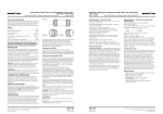
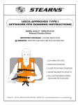
®
P/N 8-078-955-08
Brake Replacement Parts
effective 8/20/99
Service Instructions for
DC Arc Suppression Module Kit
Series 55,X00; 57,500; 87,X00; 81,X00; 82,X00 and 86,X00 Disc Brakes
Note: Two kits are required on 86,X00 Series
For definition of limited warranty/liability,
contact Rexnord Industries, Inc., Stearns
Division, 5150 S. International Dr., Cudahy,
Wisconsin 53110, (414) 272-1100.
Table: Components
Item
No.
1
2
3
4
5
6
Item Description
Arc suppression module
Cable strap
Terminal connector
Cap screw, #10-24 x 5/8
Machine screw, #6-32 x 3/8
Flat washer #6
Qty.
1
1
2
1
1
1
Caution
1. Servicing shall be in compliance with
applicable local safety codes including
Occupational Safety and Health Act
(OSHA). All wiring and electrical
connections must comply with the
National Electric Code (NEC) and local
electric codes in effect.
2. To prevent an electrical hazard,
disconnect power source before working
on the brake. If power disconnect point
is out of sight, lock disconnect in the off
position and tag to prevent accidental
application of power.
3. Be careful when touching the exterior of
an operating brake. Allow sufficient time
for the brake to cool before disassembly.
Surfaces may be hot enough to be
painful or cause injury.
4. Do not operate brake with housing
removed. All moving parts should be
guarded.
5. After usage, the brake interior will
contain burnt and degraded friction
material dust. This dust must be
removed before servicing or adjusting
the brake.
DO NOT BLOW OFF DUST using an air
hose. It is important to avoid dispersing
dust into the air or inhaling it, as this
may be dangerous to your health.
a) Wear a filtered mask or a respirator
while removing dust from the inside of
a brake.
b) Use a vacuum cleaner or a soft brush
to remove dust from the brake. When
brushing, avoid causing the dust to
become airborne. Collect the dust in
a container, such as a bag, which can
be sealed off.
6. Maintenance should be performed only
by qualified personnel familiar with the
construction and operation of the brake.
7. For proper performance and operation,
only genuine Stearns parts should be
used for repairs and replacements.
Important
Please read these instructions carefully
before servicing your Stearns brake. Failure
to comply with these instructions could cause
injury to personnel and/or damage to property
if the brake is serviced or operated incorrectly.
Warning! Any mechanism or load held in
position by the brake should be secured to
prevent possible injury to personnel or
damage to equipment before any
disassembly of the brake is attempted or
before the manual release knob or lever is
operated on the brake.
Instructions: Housing Removal
1. To remove housing, follow instructions
listed for the appropriate brake series.
2. The arc suppression module kit is a
direct replacement for capacitor and
mounting plate assembly or existing arc
suppression module.
Observe the style of brake you have and
follow the method of installation shown in
the appropriate figure.
Note on the 55,700 Series, the
capacitors had to be remotely mounted.
Remove them and the wiring from them
to the brake.
3. Connection: The two leads of
the arc suppression module are to be
connected to the two terminal screws of
the DC switch in parallel with the two
leads from the coil. Polarity is
immaterial.
55,000 Series
55,700 Series
Remove housing nuts (15) by
unscrewing from housing studs (150).
Remove housing (7) by pulling back.
a) Remove housing (7) by unscrewing nuts
from the four mounting studs (128) that
protrude through the reducer flange.
b) Grasp the coupler brake and motor as a
unit and pull free from the reducer.
c) Pull housing from the mounting studs
(128). These studs are threaded into the
C-face and should remain in place.
55,200 Series
87,000, 87,100 and 87,400 Series
4. Reassemble housing, etc. in reverse
order of the appropriate Section of
Step 1.
NOTE: For complete instructions, with
troubleshooting, request sheet
applicable to the series of brake that you
have.
87,700 Series
a) Remove the brake and motor as a
unit from the gear reducer.
b) Remove four housing cap screws
(15), lock washers (15W), housing (7)
and shaft assembly by pulling back.
81,X00, 82,X00 and 86,X00 Series
a) Remove wraparound sheet metal
housing (7) by turning wing-nut or
latch counterclockwise until the latch
releases.
b) Open housing and slide over the brake
or away from the floor stand (34).
55,500 and 57,500 Series
Remove housing nuts (15 by
unscrewing from housing studs (150).
Remove housing (7) by pulling back.
Copyright© 1999 by Rexnord Industries, Inc.
Remove manual release knob (148), two
housing nuts (15), and housing (7) by
pulling back.
87,200 Series
a) Remove any accessories, sprockets,
sheaves, etc. from brake shaft on
housing side.
b) Remove manual release knob (148),
two housing nuts (15), and housing (7)
by pulling back.
Remove manual release knob (148),
two knobs on 86,X00. Remove all the
housing screws (15) and washers
(15W). Pull the housing (7) off.
Rexnord Industries, Inc., Stearns Division, 5150 S. International Dr., Cudahy, Wisconsin 53110 (414) 272-1100 Fax (414) 277-4364