1
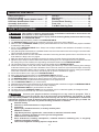
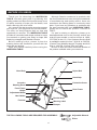
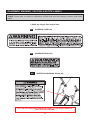
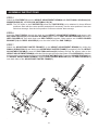
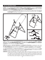
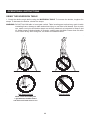
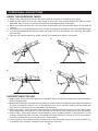
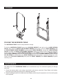
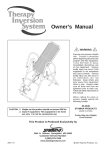
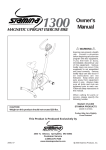
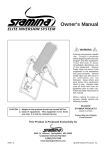
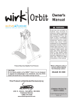
READ AND FOLLOW THE WARNINGS AND INSTRUCTIONS IN THIS OWNER’S MANUAL.
ANY PREVIOUSLY PROVIDED OWNER’S MANUALS OR INSTRUCTIONAL DVD THAT
ACCOMPANIED THIS PRODUCT OR CONTAINED HEREIN SHOULD BE DISCARDED AND
REPLACED WITH THIS UPDATED VERSION. REFER TO PAGE 5 FOR INSTRUCTIONS ON
WHERE TO AFFIX THE NEW INVERSION WARNING DECAL.
Owner's
Manual
!
WARNING
Exercise can present a
health risk. Consult a
physician before beginning
any exercise program with
this equipment. If you feel
faint or dizzy, immediately
discontinue use of this
equipment. Serious bodily
injury can occur if this
equipment is not assembled
and used correctly. Serious
bodily injury can also occur
if all instructions are not
followed. Keep others and
pets away from equipment
when in use. Always make
sure all bolts and nuts are
securely tightened prior to
each use. Follow all safety
instructions in this manual.
Product May Vary Slightly From Pictured.
WARNING: The Buckle Strap and the Nylon Strap must be
attached and properly adjusted at all times during
use of this product.
When calling for parts or
service, please specify
the following number :
Model#: 55-1527,
55-1527B,
55-1527C
CAUTION: Weight on this product should not exceed 250 lbs.
This Product is Distributed Exclusively by
STAMINA PRODUCTS
2040 N. Alliance, Springfield, MO 65803
Customer Service
1 (800) 375-7520
www.staminaproducts.com
MADE IN CHINA
© 2011 Stamina Products, Inc.
2011, 03
TABLE OF CONTENTS
Storage ....................................................... 14
Maintenance ...............................................14
Warranty ..................................................... 15
Product Parts Drawing ..............................16
Parts List .................................................... 17
Fax/Mail Ordering Form ............................ 18
Safety Instructions ...................................... 2
Before You Begin ........................................ 4
Equipment Warning, Caution & Notice Labels ... 5
Hardware Identification Chart .................... 6
Assembly Instructions ................................ 7
Operational Instructions ........................... 11
SAFETY INSTRUCTIONS
!
WARNING This product contains a chemical known to the State of California to cause cancer and
!
WARNING To reduce the risk of serious injury, read the following Safety Instructions before using
birth defects or other reproductive harm.
the INVERSION TABLE.
1. Read all warnings and cautions posted on the INVERSION TABLE.
2. The INVERSION TABLE should only be used after a thorough review of the Owner’s Manual.
3. Make sure that the INVERSION TABLE is properly assembled before use. We recommend that two people be available
for assembly of this product.
4. Do not use the INVERSION TABLE alone. Always have a helper available in case assistance is needed in recovering
from the inverted position.
5. Verify that adequate head clearance is available between the user’s head and the floor before using this inversion table.
This is especially important for tall users.
6. Make sure that the Pivot Arms are assembled to the Main Frame using the same position hole in each Pivot Arm. Pay
close attention to Steps 3 and 4 on page 8.
7. Make sure that the Pivot Arms are always secured to the pegs on the Main Frame with the Bolts and Washers.
8. Adjust the Nylon Straps to limit the Main Frame rotation to an angle of 15 to 20 degrees from the top position and use
this setting until you have verified your height setting and become familiar with the INVERSION TABLE.
9. Use the lowest holes in the Pivot Arms until you become familiar with the INVERSION TABLE.
10. DO NOT ALLOW table to invert past vertical. Table inverting past vertical may result in table contacting frame, damage
to table and serious injury to user due to fall hazard. Prior to each use, make sure nylon and buckle straps are securely
attached, as instructed in Steps 9 and 10 on page 10. Adjust straps to desired angle of inversion, making sure that Main
Frame does not strike Front Frame at any time during use, as shown in illustrations on page 12.
11. Do not allow children to use or play on the INVERSION TABLE.
12. Keep small children and pets away from the INVERSION TABLE at all times.
13. The INVERSION TABLE should not be used by persons weighing more than 250 lbs.
14. The INVERSION TABLE should not be used by persons over 6 feet 6 inches tall.
15. It is recommended that you place this exercise equipment on an equipment mat.
16. Use the INVERSION TABLE only on a level surface.
17. Wear appropriate clothing when exercising; do not wear loose clothing that could become caught in the INVERSION TABLE.
18. Be sure that there is enough room for the bed to rotate completely.
19. Use the INVERSION TABLE only as described in the manual.
20. The safety level of the INVERSION TABLE can be maintained only if it is examined regularly for damage and wear.
21. This equipment is for home use only. It is not for commercial use.
! WARNING Consult your physician before starting this or any exercise program. This is
especially important if you are over the age of 35, have never exercised before, are pregnant, or suffer
from any health problem. This product is for home use only. Do not use in institutional or commercial
applications. Failure to follow all warnings and instructions could result in serious injury or death. Do
not use this equipment if you have any of the following conditions or ailments:
Extreme obesity
Glaucoma, retinal detachment or conjunctivitis
Pregnancy
Spinal injury, Cerebral Sclerosis, or acutely swollen joints
Middle ear infection
High blood pressure, hypertension, recent stroke or transient ischemic attack
Heart or circulatory disorders for which you are being treated
Hiatus hernia or ventral hernia
Bone weaknesses including osteoporosis, unhealed fractures, medullary pins, or surgically
implanted orthopedic supports.
Use of anti-coagulants including aspirin in high doses.
2
Call Us First
Customer Service
1 (800) 375-7520
www.staminaproducts.com
THANK YOU FOR PURCHASING THE
INVERSION TABLE
To enact your warranty, please register your product
by going to register.staminaproducts.com
To help you get started, we have pre-assembled most of your
INVERSION TABLE at the factory with the exception
of those few parts left unassembled for shipping purposes.
Simply follow the few assembly instructions set forth in this manual.
With regular workouts, you will be getting your body into shape
and be on your way to achieving a happier and healthier lifestyle.
Should you have any questions,
please call our Customer Service Department toll-free number,
1 (800) 375-7520
Monday - Thursday, 7:30 A.M. - 5:00 P.M., Central Time.
Friday, 8:00 A.M. - 3:00 P.M., Central Time.
ONLINE
CUSTOMER SERVICE
[email protected]
www.staminaproducts.com
TELEPHONE
FAX
CUSTOMER SERVICE
Tel: 1 (800) 375-7520
CUSTOMER SERVICE
Fax: (417) 889-8064
3
MAIL
STAMINA PRODUCTS, INC.
ATTN: Customer Service
P.O. Box 1071
Springfield, MO. 65801-1071
BEFORE YOU BEGIN
Thank you for choosing the INVERSION
TABLE. We take great pride in producing this
quality product and hope it will provide many hours
of quality exercise to make you feel better, look
better, and enjoy life to its fullest.
It's a proven fact that a regular exercise program
can improve your physical and mental health.
Too often, our busy lifestyles limit our time and
opportunity to exercise. The INVERSION TABLE
provides a convenient and simple method to begin
your assault on getting your body in shape and
achieving a happier and healthier lifestyle.
Before reading further, please review the
drawing below and familiarize yourself with the
parts that are labeled.
Read this manual carefully before using the
INVERSION TABLE.
Although Stamina constructs its products with
the finest materials and uses the highest standards
of manufacturing and quality control, there can
sometimes be missing parts or incorrectly sized
parts. If you have any questions or problems with
the parts included with your INVERSION TABLE,
please do not return the product. Contact us
FIRST!
If a part is missing or defective, please go to
staminaproducts.com to the Services section and
order the part needed, or call us toll free at 1-800375-7520 (in the U.S.). Our Customer Service Staff
is available to assist you from 7:30 A.M. to 5:00 P.M.
(Central Time) Monday through Thursday and 8:00
A.M. to 3:00 P.M. (Central Time) on Friday.
Be sure to have the name and model number of
the product available when you contact us.
Main Frame
Hand Grip
Nylon Bed
Hand Grip
Inversion
Warning Decal
Protective Cover
Front Frame
Rear Frame
Height
Adjustment Beam
Heel Holder
Buckle Strap
Footrest
Warning Label
Bumper
THE FOLLOWING TOOLS ARE REQUIRED FOR ASSEMBLY :
Adjustable Wrench
Pliers
4
EQUIPMENT WARNING, CAUTION & NOTICE LABELS
This chart is provided to help identify the warning, caution, and notice labels on the INVERSION
TABLE. Please take a moment to familiarize yourself with all of the warning, caution, and notice
labels.
Labels are larger than actual size
W1
WARNING LABEL(44)
W2
WARNING DECAL(45)
W3
INVERSION WARNING DECAL(46)
ATTACH THE INVERSION WARNING DECAL TO THE MAIN FRAME AT
THE LOCATION SHOWN.
5
HARDWARE IDENTIFICATION CHART
This chart is provided to help identify the hardware used in the assembly process. Place the washers or
the ends of the bolts or screws on the circles to check for the correct diameter. Use the small scale to
check the length of the bolts and screws.
3/16"
1/4"
5/16"
3/8"
1/2"
INCHES
0
0
1/2
10
1
20
1/2
30
40
2
50
1/2
60
3
70
1/2
80
4
1/2
5
1/2
90 100 110 120 130 140 150
MILLIMETERS
6
8
10
6
in.
mm.
length
12
NOTICE: The length of all bolts and screws, except those with flat
heads, is measured from below the head to the end of the bolt
or screw. Flat head bolts and screws are measured from the
top of the head to the end of the bolt or screw.
length
After unpacking the unit, open the hardware bag and make sure that you have all the following items.
Some hardware may be already attached to the part.
Part No. and Description
Qty
32
34
Bolt, Hex Head (M6 x 1 x 45mm)
Bolt, Hex Head (M8 x 1.25 x 50mm)
2
2
35
36
Nylock Nut (M6 x 1)
Nylock Nut (M8 x 1.25)
2
2
38
42
Washer (M8)
Large Washer (M6)
4
2
43
Bolt, Button Head (M6 x 1 x 8mm)
2
6
ASSEMBLY INSTRUCTIONS
Place all parts from the box in a cleared area and position them on the floor in front of you. Remove
all packing materials from your area and place them back into the box. Do not dispose of the packing
materials until assembly is completed. Read each step carefully before beginning. If you are missing
a part, please go to staminaproducts.com to the Services section and order the part needed, e-mail
us at [email protected], or call us toll free at 1-800-375-7520 (in the U.S.). Our
Customer Service Staff is available to assist you from 7:30 A.M. to 5:00 P.M. (Central Time) Monday
through Thursday and 8:00 A.M. to 3:00 P.M. (Central Time) on Friday.
STEP 1
Unfold the BASE ASSEMBLY to an upright position by moving the FRONT FRAME(1) away from the
REAR FRAME(2). Then push down on the middle of the two FOLDING LINKAGES(3) until they are fully
locked down.
STEP 2
Slide one PROTECTIVE COVER(21) onto each side of the BASE ASSEMBLY, and pull the covers down
until the bottom of the covers are slightly lower than the FOLDING LINKAGES(3). Secure the PROTECTIVE
COVERS(21) to the FOLDING LINKAGES(3) with the SECURING STRAPS on the bottom of the covers.
NOTE: When the PROTECTIVE COVERS(21) are assembled correctly, the FOLDING LINKAGES(3)
should not be visible. Refer to the illustration.
7
ASSEMBLY INSTRUCTIONS
STEP 3
Slide the bottom of the two PIVOT ARMS(5) into the brackets located at each side of the MAIN FRAME(4).
Align the desired hole on the arm with the peg on the bracket, and insert the peg into the hole to lock the
PIVOT ARMS(5) in position. Then secure the PIVOT ARMS(5) on the pegs with BUTTON HEAD BOLTS
(M6x1x8mm)(43) and LARGE WASHERS(M6)(42).
PIVOT ARM ADJUSTMENT:
There are three adjustment holes on the PIVOT ARMS(5) allowing you to position the MAIN FRAME(4)
at three different heights. The lowest hole will allow the least amount of inversion angle. The top hole will
allow the greatest amount of inversion angle.
CAUTION: 1. Use the lowest holes in the PIVOT ARMS(5) until you become familiar with the INVERSION
TABLE.
2. Both PIVOT ARMS(5) must be adjusted to the same hole. Trying to adjust the PIVOT
ARMS(5) to different positions could cause damage to the machine, and injury to the user.
STEP 4
Attach the MAIN FRAME(4) with the adjusted PIVOT ARMS(5) onto the REAR FRAME(2) by sliding the
slots in the ends of the two PIVOT ARMS(5) into the slots on the REAR FRAME(2).
SLOTS
8
ASSEMBLY INSTRUCTIONS
STEP 5
Attach the FOOTREST(8) onto the HEIGHT ADJUSTMENT BEAM(6) with BOLTS(M8x1.25x50mm)(34),
WASHERS(M8)(38), and NYLOCK NUTS(M8x1.25)(36).
NOTE: The five holes in the FOOTREST(8) allow the FOOTREST(8) to be attached in three different
positions. Start with the center position and adjust if necessary. Use the outer position if users are
taller than average. Use the inner position if users are shorter than average.
STEP 6
Insert the PAD TUBE(9) through the hole on the HEIGHT ADJUSTMENT BEAM(6) and secure with
BOLT(M6x1x45mm)(32) and NYLOCK NUT(M6x1)(35). Place a HEEL HOLDER BRACKET(10) onto a
HEEL HOLDER(11), then slide them onto PAD TUBE(9) together. Slide another set of HEEL HOLDER
BRACKET(10) and HEEL HOLDER(11) over the other end of the PAD TUBE(9).
STEP 7
Attach the ADJUSTABLE INSTEP FRAME(7) to the HEIGHT ADJUSTMENT BEAM(6) by pulling the
SMALL SPRING PIN(13) and sliding the ADJUSTABLE INSTEP FRAME(7) completely into the HEIGHT
ADJUSTMENT BEAM(6). Insert the BOLT(M6x1x45mm)(32) halfway through the square tube on the
HEIGHT ADJUSTMENT BEAM(6), slide the bolt through the ring at the bottom of the SPRING(12), slide the
bolt through the square tube and secure with NYLOCK NUT(M6x1)(35). Press the SQUARE PLUG(40) into
the HEIGHT ADJUSTMENT BEAM(6). Install a HEEL HOLDER BRACKET(10) and HEEL HOLDER(11)
onto both sides of the ADJUSTABLE INSTEP FRAME(7).
9
SET UP INSTRUCTIONS
STEP 8: Install the HEIGHT ADJUSTMENT BEAM(6) into MAIN FRAME(4) by pulling the LARGE SPRING
PIN(16) on the MAIN FRAME(4) and inserting the HEIGHT ADJUSTMENT BEAM(6) as shown. For added
safety, thread the LOCKING KNOB(17) into back side of the MAIN FRAME(4).
WARNING:Do not use the INVERSION TABLE until you have verified your height setting. Failure to use
the proper height setting can result in difficulty recovering from the decline position. See HEIGHT
ADJUSTMENT instructions on page 11.
1.
2.
BUCKLE
A.
BUCKLE
B.
3.
C.
STEP 9: Attach the end of the NYLON STRAP(25) to the hook on the back of the MAIN FRAME(4);
attach the end of the BUCKLE STRAP(26) to the hook on the FRONT FRAME(1), as shown in
Illustration 2. The NYLON STRAP(27) must be secured to the MAIN FRAME(4) and the BUCKLE
STRAP(26) must be secured to the FRONT FRAME(1).
STEP 10: Attach the NYLON STRAP(25) to the BUCKLE STRAP(26) by inserting the end of the
NYLON STRAP(25) through the bottom of the BUCKLE, as shown in Illustration 3 (Steps A, B and C).
The NYLON STRAP(25) must be securely attached to the BUCKLE STRAP(26) through the BUCKLE.
The NYLON STRAP(25) and BUCKLE STRAP(26) are used to control the decline angle of the MAIN
FRAME(4). Check the decline angle before using the INVERSION TABLE. To increase the decline,
lengthen the straps. To decrease the decline, shorten the straps.
WARNING:DO NOT ALLOW table to invert past vertical. Table inverting past vertical may result in table
contacting frame, damage to table and serious injury to user due to fall hazard. Prior to each
use, make sure nylon and buckle straps are securely attached, as instructed in Steps 9 and
10. Adjust straps to desired angle of inversion, making sure that Main Frame does not strike
Front Frame at any time during use, as shown in illustrations on page 12.
10
OPERATIONAL INSTRUCTIONS
GENERAL PRECAUTIONS
1. Use the lowest holes in the PIVOT ARMS(5) until you become familiar with the INVERSION TABLE.
2. Do not use the INVERSION TABLE alone. Always have a helper available in case assistance is needed
in recovering from the decline position.
3. Make sure that the HEEL HOLDERS(11) are holding your feet securely.
4. Make sure that the HEIGHT ADJUSTMENT BEAM(6) is properly set for your height.
5. Make sure that the HEIGHT ADJUSTMENT BEAM(6) is held securely by both the LARGE SPRING
PIN(16) and the LOCKING KNOB(17).
6. Make sure that there is enough room for the bed to rotate completely.
HEIGHT ADJUSTMENT
The INVERSION TABLE is a very sensitive balance device. It responds to very slight changes in weight
distribution. It is very important to make sure that the height adjustment is set properly. Use the following
procedure to set the height adjustment and balance the INVERSION TABLE.
1. Adjust the NYLON STRAPS to restrict
movement to approximately 15 degrees
beyond the horizontal position. The nylon
straps should not allow the INVERSION
TABLE to go into the full inversion position
while you are setting the height adjustment.
2. Loosen the LOCKING KNOB(17) under the
MAIN FRAME(4).
3. Pull the LARGE SPRING PIN(16) and use
the SCALE DECAL(14) to set the HEIGHT
ADJUSTMENT BEAM(6).
4. Tighten the LOCKING KNOB(17).
5. Mount the machine.
6. Lock your ankles into the HEEL HOLDERS
(11).
7. Lie back with your hands at your sides.
8. Slowly raise your hands to your chest.
9. If your feet are higher than your head,
dismount and try a taller setting. If you do not
rotate to a position close to level, dismount
and try a shorter setting.
NOTE: 1. The INVERSION TABLE should return to the upright position when your hands are below your
waist. If it does not, use a taller setting.
2. Verify that adequate head clearance is available between the user's head and the floor before
using this inversion table. This is especially important for tall users.
THE HANDLEBARS
For added convenience, and safety, a set of HANDLEBARS has been added to the INVERSION TABLE.
These HANDLEBARS are located at the top of the REAR FRAME(2). The HANDLEBARS are to help you
return to the upright position from any degree of inversion. If you wish to return to the upright position, and
the bed is moving too slowly, or not moving at all, simply grab the HANDLEBARS and pull on them until
you return to the upright position.
11
OPERATIONAL INSTRUCTIONS
USING THE INVERSION TABLE
1. Check the decline angle before using the INVERSION TABLE. To increase the decline, lengthen the
straps. To decrease the decline, shorten the straps.
WARNING:DO NOT ALLOW table to invert past vertical. Table inverting past vertical may result in table
contacting frame, damage to table and serious injury to user due to fall hazard. Prior to each
use, make sure nylon and buckle straps are securely attached, as instructed in Steps 9 and
10. Adjust straps to desired angle of inversion, making sure that Main Frame does not strike
Front Frame at any time during use, as shown in illustration below.
Gap
Not Past Vertical
Past Vertical
NOTE: There must always be
a gap between the Main Frame
and the Front Frame when in use.
12
OPERATIONAL INSTRUCTIONS
USING THE INVERSION TABLE
2. Start by lying fully back on the bed with your hands at your side, or resting on your thighs.
3. Keeping your hands close to your body begin to raise your arms slowly allowing the table to rotate
backward. Stop, or lower your arms to control the downward rotation of the table.
4. Raise your arms until they are over your head. At this point, the inversion table will be as far back as
it can go.
5. As you get more comfortable with the use, rock the bed slowly by moving your arms up and down slowly.
6. It is recommended that the inversion table be used for five or ten minutes each morning, and again
each evening.
7. Return to the upright position by slowly moving your hands back down to your thighs.
1.
3.
2.
4.
SUGGESTIONS FOR USE
1. Begin slowly: Invert only 15-20 degrees to begin with. Stay inverted only as long as you are comfortable.
Return upright slowly.
2. Make gradual changes: Increase the angle only if it is comfortable. Increase the angle only a few degrees
at a time. Increase the time of use 1-2 minutes up to ten over a period of weeks. Add stretching and
light exercise only after you are comfortable with inversion.
3. Watch your body: Come up slowly, dizziness after a session means you came up to fast. Wait a while
after eating before using table. If you get nauseous, do not fight it, come up as soon as you feel queasy.
4. Keep moving: Movement may be accomplished by either rhythmic traction or light exercise. Do not
exercise strenuously while inverted. Limit partial inversion without movement to one or two minutes.
Limit full inversion with no movement to only a few seconds.
5. Invert regularly: We recommend two or three times a day depending upon your current condition. Try
to schedule your inversion sessions for the same times each day.
13
STORAGE
FOLDING THE INVERSION TABLE
The INVERSION TABLE can be easily folded for storage.
To fold the INVERSION TABLE loosen the LOCKING KNOB(17) and pull out the LARGE SPRING
PIN(16). Now, slide the HEIGHT ADJUSTMENT BEAM(6) all the way up into the MAIN FRAME(4) until
the ADJUSTABLE INSTEP FRAME(7) is just below the MAIN FRAME(4), release the LARGE SPRING
PIN(16) and slide the HEIGHT ADJUSTMENT BEAM(6) slightly up or down until the spring pin locks the
beam in place. Remove the MAIN FRAME ASSEMBLY from the BASE by lifting up on the MAIN FRAME(4)
until the PIVOT ARMS(5) come out of the slots located at the top of the REAR FRAME(2), (Make sure the
NYLON STRAP is not attached to the MAIN FRAME(4) before attempting to remove it.) Push up on the
center of the FOLDING LINKAGES(3) and push the FRONT FRAME(1) and REAR FRAME(2) together
until they meet.
MAINTENANCE
The safety level of the INVERSION TABLE can be maintained only if it is examined regularly for damage
and wear.
1. Check the warning label, nylon strap, strap buckle, pivot arms, nylon bed, Foam Pads, heel holders,
small spring pin and large spring pin for damage and wear.
2. Replace damaged and worn components immediately and/or keep the equipment out of use until repairs
are completed.
14
LIMITED WARRANTY
WARRANTY
Stamina Products, Inc. warrants that this product will be free from defects in materials and workmanship
under normal use, service and proper operation for a period of 90 days on the parts and five years on
the frame from the date of the original purchase from an authorized retailer. THIS WARRANTY SHALL
NOT APPLY TO ANY PRODUCT WHICH HAS BEEN SUBJECT TO COMMERCIAL USE, ABUSE,
MISUSE, ALTERATION OF ANY TYPE OR CAUSE OR TO ANY DEFECT OR DAMAGE CAUSED BY
REPAIR, REPLACEMENT, SUBSTITUTION OR USE WITH PARTS OTHER THAN PARTS PROVIDED
BY STAMINA PRODUCTS, INC. Commercial use includes use of the product in athletic clubs, health
clubs, spas, gymnasiums, exercise facilities, and other public or semipublic facilities whether or not the
product's use is in furtherance of a profit making enterprise, and all other use which is not for personal,
family, or household purposes.
To implement this limited warranty, send a written notice stating your name, date, and place of purchase
and a brief description of the defect along with your receipt to Stamina Products, Inc. P.O. Box 1071,
Springfield Missouri, USA, 65801-1071, or email us at [email protected], or
call us at 1-800-375-7520. If the defect is covered under this limited warranty, you will be requested to
return the product or part to us for free repair or replacement at our option. NO ACTION FOR BREACH
OF THIS LIMITED WARRANTY MAY BE COMMENCED MORE THAN ONE (1) YEAR AFTER THE
DATE THE ALLEGED BREACH WAS OR SHOULD HAVE BEEN DISCOVERED. NO ACTION FOR
BREACH OF ANY IMPLIED WARRANTY MAY BE COMMENCED MORE THAN ONE (1) YEAR AFTER
DELIVERY OF THE PRODUCT TO THE PURCHASER. This limited warranty is not transferable. IF
ANY PART OF THE PRODUCT IS NOT IN COMPLIANCE WITH THIS LIMITED WARRANTY OR ANY
IMPLIED WARRANTY, THE REMEDY OF REPAIR OR REPLACEMENT IS THE EXCLUSIVE REMEDY
AVAILABLE TO YOU. In the event that the purchaser makes any claim under this limited warranty or any
implied warranty, the Warrantor reserves the right to require the product to be returned for inspection,
at the purchaser's expense, to the Warrantor's premises in Springfield, Missouri. Return of the enclosed
warranty registration card is not required for warranty coverage, but is merely a way of establishing the
date and place of purchase.
Stamina Products, Inc. SHALL NOT BE LIABLE FOR THE LOSS OF USE OF ANY PRODUCT, LOSS
OF TIME, INCONVENIENCE, COMMERCIAL LOSS OR ANY OTHER INDIRECT, CONSEQUENTIAL,
SPECIAL OR INCIDENTAL DAMAGES DUE TO BREACH OF THE ABOVE WARRANTY OR ANY
IMPLIED WARRANTY.
This limited warranty is the only written or express warranty given by Stamina Products, Inc. This
warranty gives you specific legal rights, and you may also have other legal rights which vary from state
to state. ANY OTHER RIGHT WHICH YOU MAY HAVE, INCLUDING ANY IMPLIED WARRANTY OR
MERCHANTABILITY OR FITNESS FOR A PARTICULAR PURPOSE, IS LIMITED IN DURATION TO
THE DURATION OF THIS WARRANTY.
The laws in some jurisdictions restrict the rights of manufacturers and distributors of consumer goods
to disclaim or limit implied warranties and consequential and incidental damages with respect thereto.
If any such law is found to be applicable, the foregoing disclaimers and limitations of and on implied
warranties and consequential and incidental damages with respect thereto shall be disregarded and shall
be deemed not to have been made to the extent necessary to comply with such legal restriction.
15
PRODUCT PARTS DRAWING
BACK
FRONT
16
PARTS LIST
PART#
PART NAME
QTY
1
2
3
4
5
6
7
8
9
10
11
12
13
14
15
16
17
18
19
20
21
22
23
24
25
26
27
28
29
30
31
32
33
34
35
36
37
38
39
40
41
42
43
44
45
46
Front Frame
Rear Frame
Folding Linkage
Main Frame
Pivot Arm
Height Adjustment Beam
Adjustable Instep Frame
Footrest
Pad Tube
Heel Holder Bracket
Heel Holder
Spring
Small Spring Pin
Scale Decal
Bushing
Large Spring Pin
Locking Knob
Foam Pad
Double sided Tape
Nylon Bed
Protective Cover
Hand Grip
Bumper
Hook
Nylon Strap
Buckle Strap
Hollow Cap
Round Plug (7/8")
Square Plug (1 5/16" x 1 5/16")
Oval Plug (20mm x 60mm)
Bolt, Round Head (M6 x 1 x 30mm)
Bolt, Hex Head (M6 x 1 x 45mm)
Bolt, Hex Head (M8 x 1.25 x 23mm)
Bolt, Hex Head (M8 x 1.25 x 50mm)
Nylock Nut (M6 x 1)
Nylock Nut (M8 x 1.25)
Washer (M6)
Washer (M8)
Spring Pin
Square Plug (1 1/2" x 1 1/2")
Manual
Large Washer (M6)
Bolt, Button Head (M6 x 1 x 8mm)
Warning Label
Warning Decal
Inversion Warning Decal
1
1
2
1
2
1
1
1
1
4
4
1
1
1
2
1
1
1
1
1
2
2
1
2
1
1
1
4
1
2
4
2
2
2
6
4
8
8
1
2
1
2
2
1
1
1
17
TO CONTACT CUSTOMER SERVICE
For your convenience, Stamina’s customer service representatives can be reached by email at customerservice@
staminaproducts.com or by phone at 1-800-375-7520 (in the U.S.). Our customer service representatives are available Monday
through Thursday from 7:30 a.m. until 5:00 p.m., and Friday 8:00 a.m. until 3 p.m. Central Time.
ONLINE
CUSTOMER SERVICE
[email protected]
www.staminaproducts.com
TELEPHONE
CUSTOMER SERVICE
Tel: 1 (800) 375-7520
MAIL
STAMINA PRODUCTS, INC.
ATTN: Customer Service
P.O. Box 1071 Springfield, MO. 65801-1071
FAX
CUSTOMER SERVICE
Fax: (417) 889-8064
Would you like to recieve email information or special offers from Stamina Products? Register at contact.staminaproducts.com
TO REGISTER YOUR PRODUCT
To enact your warranty, please register your product by going to register.staminaproducts.com. Please have your product model
number (printed on the cover of this owner’s manual) and the serial number (printed on the black and white sticker on your
product) ready.
If you don’t have internet access, you can call customer service at 1-800-375-7520, or fill out and mail the product registration
form below to Stamina Products, Inc.; P.O. Box 1071; Springfield, MO 65801-1071.
PRODUCT REGISTRATION FORM
Stamina Products, Inc.
P.O. Box 1071
Springfield, MO 65801-1071
Model Number: ......................................................................................
Serial Number: .............................................................................................
Product Name: ..................................................................................................................................................................................................................................
Place Purchased: ..............................................................................................................................................................................................................................
Date of Purchase: ..................................................................................
Purchase Price: ............................................................................................
First Name: ............................................................................................
Last Name: ...................................................................................................
City: ..................................................................
State: ................................................................
Email Address: .......................................................................................
Phone #: (
Zip Code: .................................................
) ......................................................................................
Would you like to receive email information or special offers from Stamina Products?* ____Yes ____No
*If yes, be sure your email address is included above.
Detach and Mail or Fax the Form Above
TO ORDER PARTS
If there are missing or damaged parts, you can go to parts.staminaproducts.com and order those parts. If you have questions,
please contact customer service. Do not return the product. To order parts by mail, fill out the sheet below and fax it to
417-889-8064. The part will be mailed to your address.
Detach and Mail or Fax the Form Below
PARTS ORDER FORM
Stamina Products, Inc.
P.O. Box 1071
Springfield, MO 65801-1071
Mr./Ms: ..............................................................................................................................................................................................................................................
Address: .....................................................................................................................................
City: ..................................................................
Phone #: (
Apt. #:..........................................................................
State: ................................................................
Zip Code: .................................................
IMPORTANT : We must have your phone number to process the order!
) ................................................................................
Work Phone #: (
) .............................................................................
Date of Purchase: ..................................................................................
Model #: ............................................................................................................................................................................................................................................
Purchased From: ..............................................................................................................................................................................................................................
IMPORTANT : Before filling out the form below make sure you have the correct information.
Refer to the parts list to make sure you're ordering the right parts!
PART #
EXAMPLE:
1
DESCRIPTION
Rear Unit Assembly
QUANTITY
1