1
Series D
Ductile Iron Positive Displacement Rotary Lobe Pumps
Operating Manual
M/103/0301
Operating Manual
Alfa Laval Pumps Ltd
Birch Road, Eastbourne,
East Sussex BN23 6PQ
Tel No : (01323) 412555 Fax (01323) 412515
EC DECLARATION OF INCORPORATION
We hereby declare that the following machinery is intended for installation into a machine or to
be assembled with other machines into a machine. It must not be put into service until the
machinery into which it is incorporated has been declared in conformity with the provisions of the
Machinery Directive 89/392/EEC, amendments 91/368/EEC, 93/44/EEC, 93/68/EEC.
Machine Description
Rotary Lobe Pump
Type/Size
Serial Number
This machinery has been designed and manufactured in accordance with the following transposed
harmonised European Standards:EN292 Parts 1 and 2 : 1991 Safety of Machinery - Basic Concepts, general principles
for design.
EN294 : 1992 Safety distances to prevent danger zones being reached by the upper
limbs.
ISO9001: 1994 Quality Management System.
ISO9001 : 2000 Quality Management System.
A technical construction file for this machinery is retained at the above address.
Signed
Date
(Authorised Person)
Name
P. SWEET
Position
QUALITY MANAGER
Operating Manual
Operating Manual
Alfa Laval Pumps Ltd
Birch Road, Eastbourne,
East Sussex BN23 6PQ
Tel No : (01323) 412555 Fax (01323) 412515
EC DECLARATION OF CONFORMITY
We hereby declare that the following machinery conforms to the machinery directive 89/392/
EEC as amended by 91/368/EEC, 93/44/EEC and 93/68/EEC and to the following other
relevant directives. The machinery has been designed and manufactured in accordance with
the transposed harmonised European standards; European and national standards as listed:
Machine Description
Rotary Lobe Pump - Motorised
Type/Size
Serial Number
Other Applicable Directives
Electrical Equipment Low Voltage Directive 73/23/EEC
Electromagnetic Compatibility Directive 89/336/EEC
Applicable Standards/Specifications
EN292 Parts 1 and 2 : 1991 Safety of Machinery - Basic concepts, general principles for
design.
EN294 : 1992 Safety distances to prevent danger zones being reached by the upper limbs.
EN60204 Part 1 : 1993 Safety of Machinery - Electrical equipment of machines specification for general requirements.
BS5304 : 1988 Code of Practice for Safety of Machinery.
ISO9001 : 2000 Quality Management System.
A technical construction file for this machinery is retained at the above address.
Signed
Date
(Authorised Person)
Name
P. SWEET
Position
QUALITY MANAGER
Operating Manual
Operating Manual
Contents
1.0 General
1.1
1.2
1.3
1.4
1.5
1.6
Pump Limits of Application or Use
Duty Conditions
Noise Levels
Utility Requirements
Safety Precautions
Health and Safety Information
Page No
1
1
1
1
2
3
2.0 Unpacking, Handling and Storage
2.1
2.2
2.3
2.4
Documents
Unpacking
Handling
Pump Storage
4
4
4
5
3.0 Description of Pump or Pump Unit
3.1
3.2
3.3
3.4
3.5
General Pump Description
Principle of Operation
Pump Dimensions
Pump and Pump Unit Weights
Pump Displacement and Capacities
6
6
7
8
9
4.0 System Design and Installation
4.1
4.2
4.3
4.4
4.5
4.6
System Design Advice
Pump and Base Foundations
Installation
Coupling Misalignment
Pulley Belt Tension Adjustment
Pipework
10
11
11
12
13
14
5.0 Commissioning
5.1
5.2
5.3
5.4
5.5
5.6
5.7
5.8
Recommended Lubricants
Lubricating the Pump
Flushed Seal Arrangements
Connecting the Flush
Flushing Pipework Layout
Flushed Seal Housing Connections
Flushing Fluid
Flushing Pressure and Flow Rate
15
15
16
16
17
18
18
18
Operating Manual
Contents
Page No
6.0 Start up, Shut Down and Cleaning in Place
6.1 Start up Checklist
6.2 Pump Shut Down Procedure
6.3 Direction of Rotation
19
20
20
7.0 Maintenance and Inspection
7.1 Maintenance Schedule
7.2 Recommended Spare Parts
7.3 Maintenance Tools
21
21
22
8.0 Rotor Retention
8.1 Torque Locking Assembly - Mounting Instructions
8.2 Torque Locking Assembly - Release Instructions
8.3 Rotor Retention - Torque Locking Assembly
23
23
24
9.0 General Maintenance
9.1
9.2
9.3
9.4
9.5
9.6
9.7
9.8
9.9
Before Dismantling the Pump
Removing the Rotors
Removing the Rotorcase
Replacing the Front Gearcase Seals
Fitting and Shimming the Rotorcase
Front Cover Reversal
Removal of Rear Gearcase Cover and Replacement of Seals
Refitting the Rotors
Wearplates
25
26
27
28
29
29
30
30
31
10.0 Gearbox Components
10.1
10.2
10.3
10.4
10.5
10.6
10.7
10.8
10.9
10.10
Timing Gears
Timing Adjustment
Timing Gear Removal
Lipseal - Removal and Fitting
Fitting the Timing Gears
Shaft Removal
Bearings General
Bearings Removal
Fitting Bearings to the Shaft
Shaft Replacement
32
33
33
33
33
34
34
34
34
35
Operating Manual
Contents
Page No
11.0 Product Seal, Removals and Fittings
11.1
11.2
11.3
11.4
11.5
14.6
Single Mechanical Seal
Single Flushed Mechanical Seal
Double Mechanical Seal
Packed Gland
Packed Gland with Flush
Mechanical Sewage Seal
12.0 Faults, Causes and Remedies
36
37
38
39
40
41
42
13.0 Technical Data
13.1
13.2
13.3
Pump Information Chart
Seal Specification Chart
Torque Specification Chart
43
43
44
14.0 Exploded Drawings and Parts List
14.1
14.2
14.1
14.2
Priming Adaptor Ports
D4 Pump
D5 Pump
D6 Pump
45
46
47
48
Operating Manual
1.0 General
1.1 Pump Limits of Application or Use
This range of pumps has been designed to offer
a wide span of transfer duties throughout industry
where the use of stainless steel for pumphead
components is not essential.
Pressures of up to 15 bar, speeds to750rpm and
temperatures to 200°C can be obtained on this
range of pumps depending on pump model/size.
These conditions cannot always be obtained
simultaneously. The model type/size will be
shown on the nameplate positioned on the pump.
The pump/pump unit will have been selected
from the pump users specific application when
known and the pump serial number will relate to
this.
If the user has not specified the pumping
application or needs to change it, it is important
to confirm that the materials of construction and
product seals are compatible with the pumping
application and that adequate NPSH is available
It is therefore strongly recommended that the
user contact the supplier quoting :- pump model/
size, serial number and system details (e.g.
product, pressure, flow rate).
1.2 Pump Duty Conditions
1.3 Noise Levels
Under certain operating conditions pumps and /
or drives and / or the systems within which they
are installed can produce sound pressure levels
in excess of 85dB [A]. When necessary personal
protection against noise should be taken to
safeguard the hearing of persons who are likely
to be in close proximity to the equipment.
Please contact Alfa Laval Pumps for further
information if necessary.
1.4 Utility Requirements
Electrical Supply :This pump may be supplied bareshaft or coupled
to a drive unit for which a drive unit/electrical
supply will be required.
Note : The pump may be also driven by a diesel
drive unit.
Water Supply :Additional water supplies may be required if the
pump is fitted with a product seal flushing
arrangement. Consult your supplier for flush
fluids compatible with products pumped.
The pump should only be used for the duty for
which it has been specified. The operating
pressure, speed and temperature limits have
been selected at the time of order and MUST
NOT be exceeded for the pump. These details
are stated on the original documentation and if
not available may be obtained from your supplier
quoting :- pump model and serial number.
1
Operating Manual
1.5 Safety Precautions
All warnings in this manual are summarised on
this page.
Pay special attention to the instructions below
so that severe personal injury or damage to the
pump can be avoided.
Personnel performing installation, operation
and maintenance of the pump must have the
relevant experience required.
Installation
Warning Signs :
General safety instructions are
preceded by this symbol.
Electrical safety instructions are
preceded by this symbol.
Take great care when using caustic
agents.
: Always observe the technical data.
: The pump must be electrically connected by authorised personnel. (See the motor
instructions supplied with the drive unit).
: Never start in the wrong direction of rotation with liquid in the pump.
: Never put your hands or fingers inside the port connections
Operation
: Always observe the technical data.
: Never touch the pump or the pipelines when pumping hot liquids.
: Never stand on the pump or pipelines.
: Never run the pump with the suction side or the pressure side blocked.
: Always handle toxic and acidic liquids with great care.
: Never put your hands or fingers inside the port connections.
: In certain circumstances the gearbox and pump may become very hot. Never
touch the pump without wearing protective clothing
Maintenance
: Always observe the technical data.
: Always disconnect the pump from the drive unit and power supply when servicing
the pump.
: The pump must never be hot when servicing it.
: The pump and pipelines must never be pressurised when servicing the pump.
: Never put your hands or fingers inside the port connections.
Study this manual carefully
2
Operating Manual
1.6 Health and Safety Information
General First Aid
Potential Safety Hazards
If potentially hazardous substances are
accidentally inhaled, or skin or eyes
contaminated, then the following basic
precautions should be taken
The following section gives information on
handling, storage and disposal of parts and
materials used in the pumps which may be
considered hazardous to health.
Please pass this information on to your Safety
Officer, he may need it to comply with Health
and Safety, and COSHH regulations.
Electric motors - the pump may have an electric
motor fitted, ensure that the relevant fire
equipment is available.
The information contained here is brief.
Material
SILICON SEALANT
Inhalation -
Remove to fresh air
Skin
-
Wash with soap and water
Eyes
-
Flush with water, seek medical
attention
In all cases, if symptoms persist, seek medical
attention.
Use
Major Hazard
GEARBOX SEAL RETAINERS, REAR
COVER, GENERAL SEALANT.
RELEASES VAPOUR AT ROOM
TEMPERATURE.
SEALANT (RED HERMETITE)
GEARBOX SEAL RETAINERS, REAR
COVER, GENERAL SEALANT.
RELEASES VAPOUR AT ROOM
TEMPERATURE, HIGHLY
FLAMMABLE, TREAT AS FIRE
HAZARD.
ANTI-SEIZE COMPOUNDS
BEARINGS
APPLIED FROM AEROSOL.
RELEASES VAPOUR. DISPOSE
OF CONTAINER AS IF
PRESSURISED.
BEARING NUTS, ADJUSTMENT NUTS.
RELEASES VAPOUR AT ROOM
TEMPERATURE.
OIL - GENERAL LUBRICATION
GREASE - PRODUCT SEALS,
TIMING GEARS, GENERAL
LUBRICATION.
SKIN AND EYE IRRITANT.
PTFE - 'O' RINGS, LIP SEALS, GLAND
PACKING. POLYPROPLYENE - GLAND
GUARDS. PVC - GLAND GUARDS.
RELEASES FUMES WHEN
HEATED.
ADHESIVES (E.G. PERMABOND)
OIL AND GREASE
PLASTIC COMPOUNDS (PTFE,
POLYPROPLYENE, PVC)
ELASTOMERIC COMPOUNDS
ALL - 'O' RINGS, LIP SEALS. NITRILE,
(EP, VITON, NITRILE, NEOPRENE POLYURETHANE - ROTORS (KNOWN
AS RUBBER AND URETHANE).
ARAMID FIBRE
PAINT
RELEASES FUMES WHEN
HEATED.
GLAND PACKING.
EMMITS HARMFUL DUST.
RELEASES FUMES WHEN
HEATED.
EXTERNAL PUMP SURFACES.
RELEASES DUST AND FUMES
IF MACHINED. TREAT AS A
FIRE HAZARD.
3
Operating Manual
2.0 Unpacking, Handling and Storage
To avoid any problems, on receipt of your pump
always use the following procedure:2.1 Documents
1.
Check the delivery note against the goods
received.
2.
If the pump has been delivered with an
electric motor check that the motor
instructions are available.
2.2 Unpacking
Care must be taken when unpacking the pump,
and the following stages must be completed:1.
Inspect the packing for any possible signs
of damage in transit.
2.
Carefully remove the packing away from
the pump.
3.
Inspect the pump for any visible signs of
damage.
4.
Clean away the packing from the pump
port connections.
5.
Ensure that any additional equipment such
as seal flushing pipework is not damaged.
2.3 Handling
DLING
Refer to the pump weights guide, prior to using
any lifting gear. Use the correct lifting slings for
the pump weight (or pump and drive if
applicable).
The following details show how the pumps
should be lifted.
Bareshaft Pump :- the slings should be
wrapped around the ports and the drive shaft.
Pump with in-line Drive Unit:- the slings
should be positioned around the pump rotorcase
and under the motor.
Note :- To stop the slings slipping always cross
the slings on the lifting hooks.
Bareshaft Pump
Pump Pedestal Mounted
4
Pump with in-line Drive Unit
Operating Manual
2.4 Pump Storage
After receipt and inspection if the pump is not to
be installed immediately the pump should be
repacked and placed in suitable storage. The
following points should be noted:1.
Plastic or gasket type port covers should
be left in place.
2.
Pumps received wrapped with corrosion
inhibiting treatment material should be
rewrapped.
3.
A clean, dry, vibration free location should
be selected. If stored in a moist
atmosphere, further protect the pump or
unit with a moisture repellent cover until it
is to be installed.
4.
Rotate pump/pump unit by hand, weekly,
to prevent bearing and gear damage.
5.
All associated ancillary equipment should
be treated similarly.
6.
If the pump is fitted with a diesel/petrol
engine it is advisable to disconnect the
pump and run the engine every two
months.
5
Operating Manual
3.0 Description of Pump or Pump Unit
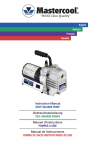
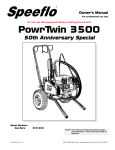
3.1 General Pump Description
The pump supplied is a positive displacement
pump, which may be supplied with or without a
drive unit (see below). The drawing below
indicates various parts of the pump.
Rotorcase
Pump
Drive Unit
Drive
Shaft
Front
Cover
Coupling Guard
(Houses Coupling)
Ports
Pump with Drive Unit
Product Seal Area
Bareshaft Pump
Gearbox
3.2 Principle of Operation
The rotors are timed such that when they rotate
no contact occurs. The direction of flow is
reversed by changing the direction of rotation
of the pump drive shaft. The pumping principle
is as follows :
As the rotors continue to rotate the product is
transferred around the outside of the rotorcase
to the discharge side.
The rotors have just come out of mesh creating
a reduction in pressure in the chamber which is
then filled with product.
The product is contained in the rotorcase
chamber.
7
The rotors lobes go into mesh and the product
is discharged from the pump.
Operating Manual
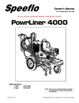
3.3 Pump Dimensions
L
'A' Port
Size
Shaft Dis
G
F
J
KW Key Width
B
KS Key & Shaft Dia
B
D
HT
C
HB
T
Q
E
R
4
Holes'U'
Ø
S
N
P
M
All dimensions in mm
PUMP
MODEL
D4-0095
A
B
C
D
E
F
G HB HT J
KS KW L
M
N
P
Q
R
S
T
U
75 170
520*
100 170
530*
163 307 20 38 80 115 211 63 41
338*
163 307 20 38 80 115 211 63 41
338*
D5-0290
100 190
550*
100 190
550*
150 190
195 371 20 45 110 135 255 70 48.5 14 699 125 279 180 35 275 210 180 14
315*
195 371 20 45 110 135 255 70 48.5 14 719 145 279 180 35 275 210 180 14
315*
195 371 20 45 110 135 255 70 48.5 14 747 145 279 180 35 275 210 180 14
D6-0420
D6-0600
150 225 225 429 20 48 110 155 295 70 51.5 14 832 163 266 260 40 370 220 190 14
150 225 225 429 20 48 110 155 295 70 51.5 14 857 188 266 260 40 370 220 190 14
D4-0140
D5-0200
D5-0290
10 597 122 225 150 35 255 184 150 14
10 628 138 225 150 35 255 184 150 14
* = Dimensions when priming adaptors are fitted
The above dimensions are for guidance only and should not be used for installation
purposes. Certified dimensions are available upon request.
8
Operating Manual
3.4 Pump and Pump Unit Weights
Pump Unit - Pump complete with Drive
Unit
Bareshaft Pump
Pump Model
Bareshaft Pump
KG
Pump with Drive Unit
KG
D4-0079
D4-0095
D4-0140
110
113
130
147
150
220
D5-0168
D5-0200
D5-0290
170
176
192
264
270
350
D6-0353
D6-0420
D6-0600
281
289
300
392
400
530
The above weights are for guidance only and will vary depending upon the
specification of the pump, baseplate and drive unit.
9
Operating Manual
3.5 Pump Displacement and Capacities
The following table details the pump capacities
for the pump models. This figure will change
depending upon speed, pressure, temperature
and product being pumped.
Pump
Ref
Displacement
litres/rev
Maximum
Speed
Water
(rpm)
Maximum Capacity
at Maximum Speed
m³/hr
D4-0079
D4-0095
D4-0140
0.79
0.95
1.40
750
500
500
35.6
28.5
42.0
D5-0168
D5-0200
D5-0290
1.68
2.00
2.90
600
500
500
60.5
60.0
87.0
D6-0353
D6-0420
D6-0600
3.53
4.20
6.00
500
500
500
106.0
126.0
180.0
10
Operating Manual
4.0 System Design and Installation
4.1 System Design Advice
When designing the pumping system :Do
Do
-
-
confirm with the supplier the Net
Positive Suction Head (NPSH)
requirements for the pump, as this is
crucial for ensuring the smooth
operation of the pump and
preventing cavitation.
avoid suction lifts and manifold/
common suction lines for two pumps
running in parallel, as this may cause
vibration or cavitation.
Do
-
fit suction and discharge pressure
gauges to monitor pressures for
diagnostic purposes.
Do
-
install non-return valve to prevent
turbining when high pressures are
applied to the pump whilst it is not in
use. Valves are also recommended
if two pumps are to be used on
manifold/common discharge lines.
Do
-
make the necessary piping
arrangements if flushing is required
for the seal.
Do
-
provide a hose cleaning facility to
assist maintenance, ensuring the
drive unit meets the specification for
hose cleaning.
Discharge Line
Plan View
Suction Line
Do
-
protect the pump against blockage
from hard solid objects e.g. nuts,
bolts etc. Also protect the pump
from accidental operation against a
closed valve by using one of the
following methods :- relief valves,
pressure switch, current monitoring
device.
Do
-
Install a motor current sensing
device which automatically reverses
the pump when an overload or jam
is detected.
Note : This is not recommended when non
return valves are fitted.
11
Operating Manual
4.2 Pump and Base Foundations
4.3 Installation
Depending on your requirements the pump
and drive (if supplied) may arrive mounted on
a baseplate. Our standard baseplates have
pre-drilled fixing holes to accept base retaining
bolts.
Before the pump is installed it is advisable to
consider the following:
Always -
Ensure that the mounting
surface is flat to avoid distortion
of the baseplate. This will
cause pump/motor shaft
misalignment and pump/motor
unit damage.
Check -
pump shaft to motor shaft
alignment once the baseplate
has been secured and adjust
as necessary.
To provide a permanent, rigid support for
securing the pump unit a foundation is required,
this will also absorb vibration, strain or shock on
the pumping unit.
Foundation Size
The foundation should be approximately
150mm longer and wider than the mounting
base of the unit. The depth of the foundation
should be proportional to the size of the pump
unit (pump complete with drive and baseplate).
For example, a large pump unit foundation
depth should be at least 20 times the diameter
of the foundation bolts.
Baseplate Fixing
Holes
Bolt Location Dimensions
The location and sizes of the relevant bolting
down holes can be provided on a certified
drawing from your supplier.
Note : Always allow at least one metre for
pump access/maintenance all around the pump.
Typical Foundations Bolts
Weight -
The drawing below shows two methods for
foundation bolt retaining. The sleeve allows for
'slight' lateral movement of the bolts after the
foundation is poured. Use rag or paper to
prevent the concrete from entering the sleeve
while the foundation is poured. A minimum of
14 days is required to allow the curing of the
concrete prior to operation.
Electrical
Supply
Consider the weight of the
pump, drive and lifting gear
requirements.
-
Ensure that there is an
adequate electrical supply
close to the pump drive unit.
This should be compatible with
the electric motor selected.
D = Diameter of foundation bolts
12
Operating Manual
4.4 Coupling Misalignment
Parallel Misalignment
When installing the pump and drive unit, it is
essential to ensure that the coupling is not
twisted during installation. The main cause of
misalignment is by fitting the baseplate to an
uneven surface.
Angular Misalignment
Check the maximum angular and parallel
allowable misalignments for the couplings
before operating the pump.
Coupling Type
Recommended
Maximum Parallel
Misalignment
Size
1
mm
Maximum Angular
Misalignment
Degrees
0.2
David Brown
± 1.5°
2
0.3
3
0.4
Nylicon Flexible
(Per Gear in Mesh)
FL63
0.25
FL80
0.75°
William Kenyon
FL112
0.3
FL125
0.4
FL160
0.5
F40
1.1
F50
1.3
F60
1.6
Flexilok
1.0°
Fenaflex
Flexible Tyres
4°
F70
1.9
F80
2.1
F90
2.4
Note : The above table indicates the common coupling types used on the pump ranges.
Details for other coupling types will be available on request.
13
Operating Manual
4.5 Pulley Belt Tension Adjustment
An incorrectly tensioned belt will cause belt
slip and short belt life. An excessively
tensioned belt will overload both belts and
bearings. Always use a belt tension gauge
fo setting up.
1.
Measure the span length.
2.
Calculate the required deflection: ('x')
Span
Isolate the drive unit and pump from all power
and control supplies before attempting to work
on adjusting the belts.
Force
'X'
100mm span length = 1mm deflection
therefore :
400mm span length = 4mm deflection
3.
Refer to the table for recommended
minimum and maximum deflection force
for small pulley diameter range.
To convert Newtons to pounds force
multiply by 0.2248.
To convert Newtons to kilogrammes
force multiply by 0.1020.
4.
Use a belt tension gauge with the figures
to determine the belt adjustment required.
5.
Belt tension adjustment is achieved by
adjusting the nuts on the pedestal frame.
6.
Finally check that all nuts are re-tightened
and the belts can move 'freely' by hand
(depending upon pump size and system
design).
7.
Ensure the pulleys are kept vertically and
horizontally to each other and aligned as
per diagrams (A) and (B).
(B)
(A)
Belt
Section
Small Pulley
Diameter
Range
Recommended
Deflection Force
Newtons
mm
min
max
XPZ
SPZ
56
60-63
67-71
75-80
85-95
100-125
132-180
7
8
9
10
11
13
16
11
13
14
15
16
19
24
XPA
SPA
80-125
132-200
18
22
27
31
Note : The above table indicates the common
pulley types used on the pump ranges. Details
for other pulley types will be available on request.
14
Operating Manual
4.6 Pipework
All pipework must be supported. The pump
must not be allowed to support any of the
pipework weight.
Remember -
Pipework supports must also
support the weight of the
product being pumped.
Keep -
Pipework horizontal where
applicable to reduce air locks.
Include eccentric reducers on
suction lines.
Check -
Coupling alignment during
installation to highlight
pipework alignment/support
problems.
Install -
A liquid trap around to pump to
assist in priming. (See below)
Always :Have -
Short straight suction lines to
reduce friction losses in the
pipework thereby improving
the NPSH available.
Use -
Long radius bends wherever
possible.
Provide - Isolating valves on each side of the
pump to isolate the pump when
necessary.
Non return valve
Fluid trapped to maintain
prime
Pipework Support
Pipework Support
15
Operating Manual
5.0 Commissioning
5.1 Recommended Lubricants
5.2 Lubricating the Pump
Pumps specified oil filled :-
Changing the Oil :-
The pump will not be supplied with oil therefore
the table below must be used to select a
recommended oil.
First change - After 150 hours of operation.
Next change - Every 3000 hours of operation.
Oil Filled
-20° C to +130° C
BP Energol GR - XP150
Castrol Alpha SP150
Mobil Gear 629
Shell Omala 150
Texaco Meropa 150
Esso Spartan EP150
Only use the oil types recommended by your
supplier.
Oil Filling -
Fill with oil through the
filler plug to the level
indicated in the sight
glass.
Pump
Model
Top
Chamber
Litres
Bottom
Chamber
Litres
Total
D4
0.35
0.75
1.10
D5
0.62
1.38
2.00
D6
1.30
2.30
3.60
Note : Ensure all ancillary drive units are
lubricated according to the manufacturers
instructions.
16
Operating Manual
5.3 Flushed Seal Arrangements
5.4 Connecting the Flush5
A flushed seal arrangement is fitted in order to
cool the seal area.
The following equipment is strongly
recommended when using a flushing system.
It is important that:-
-
Control valve and pressure gauge, to
enable the correct flushing pressure to be
obtained and monitored. (A constant flow
valve can be used).
-
Isolation valve and check valve, so that
the flush can be turned off, and to stop
any unwanted substances flowing in the
wrong direction.
-
A method of visibly indicating flushing
fluid flow e.g. using a tun dish.
-
The flush is correctly connected.
(See overleaf).
-
A compatible flushing fluid is used.
-
The fluid is supplied at the correct
pressure and flow rate.
-
The flush is turned on at the same time/
prior to starting the pump, and turned off
at the same time/after stopping the pump.
17
Operating Manual
5.5 Flushing Pipework Layout
This suggested arrangement is for single
mechnical seals. If the pump is fitted with
double mechanical seals or packed glands
the pressure gauges and control valves
should be fitted on the outlet side of the
system.
E
Note :- The pipework and fittings are
not supplied with pump.
18
Operating Manual
5.6 Flushed Seal Housing Connections
Pump Model
Single/Double
Mech. Seal
Packed
Gland
D4
1/8”
1/4”
D5
1/8”
1/4”
D6
1/8”
1/4”
All connections BSPT or NPT as specified at
the time of order.
5.7 Flushing Fluid
5.8 Flushing Pressure and Flow Rate
The choice of flushing fluid is dependant upon
the pumping media and duty conditions i.e.
pressure and temperature. Usually water is
used for cooling or flushing water soluble
products. For advice on selecting a suitable
flushing fluid please contact the supplier.
Single Mechanical Seal - 0.5 Bar maximum.
Any further increase in pressure will result in lip
seal failure.
Double Mechanical Seal/Packed Gland Seal
- 1.0 bar higher pressure compared to the
discharge pressure of the pump. If the discharge
pressure fluctuates set the flushing pressure to
suit the maximum condition.
For guidance the pressure at the seal is
approximately 2/3 of the pumping pressure.
The flushing flow rate must be adequate to
ensure that the temperature limitation of the
seals is not exceeded. Contact your supplier
for further information on the recommended
flow rate for the product seal fitted.
19
Operating Manual
6.0 Start up, Shut Down and Cleaning in Place
6.1 Pump Start-up Checklist
1.
Is the location of the 'stop' button clear?
2.
Has the pipework system been flushed
through to purge welding slag and any
other hard solids?
3.
Have all obstructions been removed
from the pipework or pump?
4.
Are the pump connections and pipework
joints tight and leak-free?
5.
Is there lubrication in the pump and
drive unit?
6.
If your product seals require flushing
has the flushing supply been fitted?
7.
Are the pipework valves open?
8.
Are all safety guards in place?
9.
Start then stop the pump, is the product
flowing in the correct direction?
Yes
No
10. Are the pump speed/pressure settings
below the pump maximum limitations?
All answers should be 'Yes' before proceeding.
If there are any pumping problems
refer to the fault finding chart.
20
Operating Manual
6.2 Pump Shut Down Procedure
1.
Turn the pump off.
2.
Isolate the pump/drive unit from all power
and control supplies.
3.
Close the pipework valves to isolate the
pump.
4.
If the pump is to be dismantled refer to the
dismantling section.
6.3 Direction of Rotation
The direction of flow is dictated by the direction
of rotation of the drive shaft. Reversing the
direction of rotation will reverse the flow
direction. Top and bottom shaft drive pumps
have opposite flow directions as illustrated.
Top Shaft
Drive Position
Discharge
Suction
Suction
Discharge
Bottom Shaft
Drive Position
21
Operating Manual
7.0 Maintenance and Inspection
7.1 Maintenance and Schedule
7.2 Recommended Spare Parts
It is advisable to install pressure gauges either
side of pump so that any problems within the
pump/pipework will be highlighted.
The following table details the recommended
spare parts which should be retained within
your maintenance stock.
Your weekly schedule should include:
Checking the oil level in the gearcase
Part Description
Checking the mechanical seals for
leakage and replacing as necessary.
Geasing the mechanical sewage seal (if
fitted).
Adjusting the packed glands to control
leakage.
Lip Seal Drive End
'O' Ring Front Cover
Lip Seal Gland End
Rotors
'O' Ring Rotor Sealing
'O' Ring Rotor Cap
Product Seals
Quantity
2
1
2
2
2
2
2
Checking the oil seals for leakage.
Check pumping pressures.
22
Operating Manual
7.3 Maintenance Tools
Dismantling and Assembly of the Pumphead
You will need - Allen keys
Spanners
Socket set
Wooden wedge
Soft mallet
Cleaning hose
Silicon grease
Torque wrench
Rotor clamp tool (supplied with pump)
Pump Head
Dismantling and Assembly of the Gearbox
You will need - A Work Shop equipped with:
A heavy duty vice
A press and pressing tools
Lifting gear
Induction heater
A method of lubrication collection
Lever soft ended
Wooden wedge
'C' spanner
Liquid gasket
Permabond 145 (or equivalent)
Torque wrench
23
Gearbox
Operating Manual
8.0 Disassembly
Rotor retention on all pumps in the DRM range
is by Torque Locking Assembly (TLA) with
flush fitting rotor caps. The rotor spline area is
sealed with three O'rings per rotor (A, B, & C),
one (A) between the shaft and rotor, and two (B
& C) seated in the rotor cap. The rotor caps are
retained by socket head cap screws. The
TLA's should be tightened to the recommended
torque values.
'O' Ring 'C'
'O' Ring 'B'
TLA
3.
Using the rotor clamp with the rotor
correctly positioned on the shaft and the
TLA in place, a suitable screw is put
through the centre hole in the clamp and
tightened into the end of the shaft. This
will hold the rotor in place and the TLA
screws may now be tightened through the
access slots in the clamp.
4.
With the rotor clamp secured in place the
TLA screws can be torqued up to the
correct settings. To obtain best results
it is recommended the screws are
tightened in a diametrically opposed
pattern, repeating until correctly set.
8.2 TLA Release Instructions
Loosen the socket head cap screw and remove
the rotor cap ensuring that the two sealing
O'rings are not lost. If the rotor cap does not
release easily it can be removed by gently
screwing a suitable screw into the thread in the
centre hole of the rotor cap.
Rotor Cap
'O' Ring 'A'
Note : 'O' ring 'A' is fitted in a recess on pumps
D5 and D6.
8.1 TLA Mounting Instructions
When fitting a TLA it is recommended that :1.
The TLA is lightly oiled on all surfaces to
assist in achieving the correct torque value
and to aid its release when removing.
2.
Once fitted into its working position and
before tightening, a temporary rotor clamp,
supplied with the pump, should be used
to ensure the rotor with TLA is positively
abutted against the shaft shoulder. This
will ensure that rotor clearance on both its
front and rear are maintained.
Loosen the TLA in several stages and in a
diametrically opposite sequence. The loosened
TLA can now be removed.
To extract the TLA from the rotor, only remove
the two screws which are fitted with washers,
carefully screw 8mm x 50mm bolts into the
holes (these holes have only 3-5 threads) and
pull out the TLA.
24
Operating Manual
8.3 Rotor Retention: Torque Locking Assembly
Rotor Clamp
TLA
Rotor
Screw
Access to TLA
through slots
Torque Values for Rotor Torque Locking Assemblies
25
Pump
Torque
Nm (lbft)
Key Size
mm
D4
4.1 (3.0)
3
D5
8.5 (6.3)
4
D6
14.0 (10.3)
5
Operating Manual
9.0 General Maintenance
9.1 Before Dismantling the Pump
Before starting to dismantle the pump
Always:Purge the pump and system if any noxious products
have been pumped.
Isolate pump/drive unit from all power and control
supplies.
Close pipework valves to isolate the pump
Disconnect the pump from the drive unit.
Read this section first before
continuing to dismantle the pump
26
Operating Manual
9.2 Removing the Rotors
1.
Before starting to dismantle the pumphead
isolate the driver/pump from all power and
control supplies, purge the system if any
noxious products have been pumped.
Read the safety section carefully.
2.
Ensure isolating valves to the pump are
closed.
3.
Carefully loosen the front cover retaining
screws, there may still be residual pressure
in the system.
4.
Remove the front cover retaining screws
and take off the cover. D5 and D6 pumps
may have hinges fitted to the front covers.
Having removed the front cover retaining
screws the cover can be swung to one
side.
5.
Flush out the pumphead with a suitable
cleaning agent before continuing.
6.
Remove the rotor cap and torque locking
assemblies.
7.
Before removing the rotors their position
should be noted such that they can be
replaced easily. Mark the master rotor
lobe, which centre line corresponds with
the rotor spline teeth. See below.
master lobe
spline teeth
27
8.
Extract the rotors which should slide out
from the splines. An internal groove is
provided in the front of the rotor into which
a suitable tool may be inserted to aid
extraction. An illustration of a typical tool is
shown below.
Typical rotor extraction tool
Operating Manual
9.3 Removing the Rotorcase
1.
Before proceeding disconnect the suction
and discharge piping.
2.
Remove the rotors as described previously.
On pumps D5 and D6 shut the hinged front
cover (where fitted) and loosely fasten with
front cover screws.
3.
5.
Between the rotorcase and gearcase,
preshaped plastic shims are used to adjust
the rotor clearances. These must be
replaced exactly as removed, otherwise
excessive wear or damage may occur to
the rotors and/or rotorcase.
6.
Once the rotorcase is removed the seals/
gland packing can be examined.
Loosen gland followers or when fitted with
a flushed seal arrangement remove the
housing retaining nuts and ease the
housing away from the rotorcase.
Shims
4.
Remove the rotorcase retaining nuts, and
tatp the rotorcase forwards with a soft mallet
until it clears the locking dowels. If the
pump is fitted with mechanical seals, care
must be taken to support the rotorcase as
it comes off the dowels otherwise the
mechanical seals may be damaged.
Shims
28
Operating Manual
9.4 Replacing the Front Gearcase Seals
1.
Follow the procedure for the removal of
rotors and rotorcase.
2.
Remove the product seal.
3.
Three socket head screws retain the seal
carrier, once removed the carrier can be
extracted. As silicon sealant or a gasket
is used to seal the faces the carrier may
have to be eased off carefully with a lever.
4.
Once the carriers are removed from the
pump the seals can be pressed out and
replacements pressed in using a suitable
dolly.
5.
6.
Before replacing the seal carriers, clean
the old silicon sealant (if used) from the
rear face of the carrier and from the front
face of the gearcase. Coat the rear face
of the carrier with new liquid gasket, slide
into position and replace the three socket
head screws. It must be noted that one of
the three screws is longer, this should be
inserted in the hole which aligns with the
largest hole in the gearcase. Tighten the
screws evenly to the recommended torque
value.
7.
Reassemble the seals and rotorcase, see
the relevant sections for refitting
procedure.
Ensure the surface area which the seal
will run on is free from scratches, if the
surface is scratched clean up damaged
area with a fine grade abrasive cloth.
Ensure that all traces of abrasive material
are cleaned away before refitting the new
oil seals.
Note : It is advisable at this point to check for
bearing end play, as this may be the cause of
the seals leaking.
Front Seals
Front Seal
Carriers
Large Holes
Longer Socket Head Screws
29
Operating Manual
9.5 Fitting and Shimming the Rotorcase
9.6 Front Cover Reversal
When fitting a rotorcase correct shimming is
critical. Shims are fitted between the rotorcase
and gearcase and are used to control the back
clearances between the rotor and rotorcase.
Plastic colour coded shims are used on all series
D pumps. If the pump has previously been
shimmed, the old shims may be reused provided
they are replaced in their original positions. It is
essential that equal shimming is used both top
and bottom of the rotorcase to ensure that equal
clearances are maintained across the rotor
faces.
The front cover of all pumps in the series D range
is of a flat and symmetrical design thus making it
reversible. Therefore, when the inside face of
the front cover becomes worn it may be reversed.
In due course both sides will become worn and
the cover will have to be replaced.
To reassemble the rotorcase the following step
by step procedure should be used :-
Check the seals are correctly fitted.
-
If the rotorcase has previously been
shimmed, replace the old shims in their
original positions.
-
Alternatively, if new shims are to be fitted
the shimming process commences with
'too few' shims. Fit the rotorcase and
torque up the gearcase nuts, fit the rotors
and tighten to the recommended torque.
With 'too few' shims fitted measure the
back clearances (the clearance between
the back of the rotors and rotorcase), and
determine the additional shimming required
to bring the clearance within tolerance.
Note : For the correct clearance dimensions
please contact your supplier.
-
Fit the additional shims, and recheck the
clearances. If necessary repeat the above
exercise until the clearances come within
tolerance.
Isolate the driver/pump from all power and control
supplies. If any noxious products have been
pumped, the system should be purged.
Ensure isolating valves to the pump are closed.
Loosen and remove the front cover retaining
screws and remove the front cover.
In the case of D5 and D6 pumps loosen and
remove the screws which hold the front cover to
the hinge. Be sure to retain the washers fitted
under the screw heads. Thoroughly clean the
front cover. Inspect 'O' ring and replace if
necessary.
Before replacing front cover simply reverse it
such that the unworn side faces the pump. In the
case of the D5 pumps ensure that the cover is
orientated such that the hinge fixing holes line up
with the hinge.
In the case of D5 and D6 pumps refit the hinge to
the cover by refitting the hinge retaining screws,
make sure that the washers are refitted under the
screw heads. Ensure that the ends of the hinge
retaining screws are flush with the inside of the
front cover when fully tightened.
Fit front cover and tighten retaining screws to the
recommended torque values.
Care should be taken when sliding the rotorcase
over the shafts so as not to damage the
mechanical seals if fitted. When fitting the shims
ensure that similar clearances are achieved both
top and bottom of the rotorcase.
30
Operating Manual
gearbox dismantled the pump will have to
be retimed as described in the timing
adjustment section.
9.7 Removal of Rear Gearcase Cover and
Replacement of Seal
1.
2.
3.
Isolate the motor, remove any coupling or
Vee belt guards.
If the pump is direct coupled it will be
necessary to disconnect the coupling and
remove the pump from the baseplate before
removing the gearcase cover.
Drain the oil from the pump.
5.
Remove the retaining screws and then
remove the gearcase cover by sliding it
along the drive shaft. As the cover is
sealed to the gearcase with a liquid gasket
it may require a sharp tap with a mallet and
punch to break the joint.
7.
8.
-
rotate the drive shaft until the keyway's
uppermost (not essential).
-
find the master lobe of the rotor which
centre line is the same as that of the
spline teeth. See below.
If the pump is belt driven, release the tension
on the belts and remove them, remove the
pulley and drive key.
4.
6.
To refit the rotors the recommended procedure
is as follows :-
With the cover removed, press out the oil
seal from the cover and replace with a new
seal.
Clean the faces of both the gearcase and
the end cover, coat the faces with a suitable
liquid gasket and refit the end cover.
Replace the retaining screws then
centralise the lipseal on the shaft before
tightening to the recommended torque
value.
centreline of lobe
centreline of
shaft
-
line the master lobe up with the shaft
spline and slide the rotor onto the shaft.
-
find the master lobe of the remaining rotor
as previously done.
-
slide the rotor on so that both rotors are in
the position shown below.
Master lobe
Master lobe
Refill the pump with oil.
9.8 Refitting the Rotorcases
1.
2.
31
All rotors in the series D pump range have
sealing 'O' rings as described previously.
Check the condition of the 'O' rings and fit
new rings if necessary.
Rotors are fully interchangeable. When
refitting the rotors correct timing is achieved
by replacing the rotors in exactly the same
positions as when removed. If the gears
have been removed or the
spline tooth
Correct timing has been achieved when
the pump rotates freely without contact
taking place between the rotors, this
should always be checked prior to running
the pump.
3.
Replace the 'torque locking assemblies'.
Refer to section 8.1 on page 23 for full
details.
4.
Before refitting the front cover examine
the 'O'ring and replace it if damaged. Fit
front cover and tighten the nuts up to the
recommended torque values.
Operating Manual
9.9 Wearplates
Replacing Wearplates
1.
Before fitting new wearplates thoroughly
clean the inside of the rotorcase where the
wearplates will be sealed. In addition wipe
clean the rear face of the new wearplates.
2.
The new wearplates will be supplied with
the studs already attached.
3.
Just prior to fitting the wearplates apply
silicon sealant, or similar, to the wearplate
studs.
4.
Insert the new wearplates through the front
of the rotorcase ensuring that the studs
pass through the holes in the rear of the
rotorcase.
5.
Assemble nuts to the studs at the rear of the
rotorcase and tighten to a torque of 8Nm
(5.9 lbft).
All pumps in the series D range can be fitted with
wearplates . When worn the wearplates can be
replaced thus increasing the life of the pump.
Wearplates can be replaced without removing
the rotorcase, but access to the wearplate
retaining nuts may be increased if the rotorcase
is removed.
Removing Old Wearplates
1.
Remove the front cover and rotors as
described. If considered necessary,
remove rotorcase.
2.
Loosen and remove the wear plate stud
retaining nuts from the rear of the rotorcase.
3.
Next the wearplates, with the studs still
attached, may be removed from the front of
the rotorcase where the wearplates will be
seated.
Fitting New Wearplates
Wearplates
32
Operating Manual
10.0 Gearbox Components
10.1 Timing Gears
Each pump is fitted with a pair of timing gears,
which are located in the rear of the gearcase and
ensure synchronisation of the rotors, such that
under normal working conditions they will not
contact one another.
The timing gears on pumps in the D range are
retained using Torque Locking Assemblies (TLA)
similar to those used to retain the rotors. The
method of correctly tightening the TLA's is the
same as for the rotors as previously described.
TLA
Timing Gears
33
Pump
Torque
Nm (lb/ft)
D4
D5
D6
14
35
35
(10)
(26)
(26)
Key Size
mm
5
6
6
Operating Manual
10.2 Timing Adjustment
The rotor timing (synchronisation) is set-up in
the factory. If the rotors become
unsynchronised, they may be retimed using
the following procedure.
To remove the timing gears the following
procedure is recommended.
1.
Drain lubricant.
2.
Remove rear gearcase cover.
3.
Release torque locking assemblies.
(refer to page 23 - 8.2)
To adjust the timing of the rotors, first remove
the gearcase end cover, once the cover is
removed the timing gears will be exposed.
4.
To retime the rotors, only one of the timing gear
retainers need to be released sufficiently, to
allow the rotors to be tapped into a position
where they are synchronised. The rotors are
correctly synchronised when the clearances at
the measurement points are equal.
An extractor tool may be required to pull
the gear off. Because the gearcase has
twin lubricated chambers lubricant may
drain out when the top gear is removed.
10.4 Lip Seal - Removal & Refitting
The cause of the fault should be
established and eliminated before
proceeding.
Diagram of Rotors Showing Timing
Measurement
Point
Measuement
Point
The bearing lip seal fits behind the top shaft
rear bearing housing. The lip seal runs on a
boss at the back of the timing gears, and
prevents the top chamber lubricant from draining
into the bottom chamber. If the lip seal is to be
reused care should be taken when extracting it
not to damage the sealing edge, otherwise a
new lip seal should be fitted. To refit a seal, it
should be pressed evenly into the hole, and a
flat plate or dolly used to drive it home.
10.5 Fitting the Timing Gears
Use feeler gauges to measure the clearances
at the positions illustrated, and adjust until
equal, the pump is then correctly timed. Tighten
the screws of the torque locking assembly to
the correct values and replace the gearcase
cover.
10.3 Timing Adjustment
Removing the timing gears is a reasonably
simple operation though difficulty may be
experienced in sliding the gears off the shaft. If
this is the case an extractor tool may be required.
For this purpose threaded holes are provided in
the gears.
1.
Fit the rotors to the shafts to establish the
timing.
2.
Check that the bearing lip seal is fitted.
Check that the boss on the back of the
gear is smooth, and smear some lubricant
onto it.
3.
Slide on the gears. Where gears are
marked as pairs they should be refitted
with the timing marks aligned.
4.
Fit the torque locking assemblies, and
torque 'one' of them up. Adjust the timing,
before tightening up of the last gear.
34
Operating Manual
10.6 Shaft Removal
1.
Remove rotorcase front cover, rotor and
rotorcase.
3.
Locate outer shell of bearing onto the
cone just fitted.
2.
Remove product seals.
4.
Locate bearing spacer onto shell just fitted.
3.
Remove the gearcase rear cover, timing
gears and drain lubricant.
5.
Locate rear bearing shell, of front set of
bearings, onto the spacer.
4.
Remove the gearcase front seal retainers
and seals.
6.
5.
The shaft assemblies can now be removed
through the front end of the gearbox, a
soft faced mallet may be used to tap them
out. The top chamber can now be
completely drained. Ensure that the
spacer located in the front bottom shaft
bearing housing is retained for refitting.
Heat rear bearing cone to 110ºC and fit to
bearing diameter. The taper should be
towards the rotor end of the shaft.
7.
Allow bearings to cool.
8.
Locate shaft in vice in horizontal position.
9.
Apply Permabond grade 145 sealant or
equivalent to the shaft front lock nut thread
and screw front lock nut onto the shaft.
Whilst continuously rotating both bearings
and spacer, torque up the bearing lock nut
until the spacer cannot be moved radially
(off the shaft centre line) by finger pressure
alone, but can be moved with a light blow
of a hammer.
10.7 Bearings - General
The DRM range of pumps utilise taper roller
bearings which are arranged in two sets of
double bearings front and back, assembled
with individual spacers. Refer to the exploded
diagrams at the rear of the manual.
10.8 Bearings Removal
To remove the bearings, undo the notched
bearing nut using a C- spanner, the bearing
assembly can now be dismantled. The bearing
cones are shrunk onto the shaft and will require
pressing off.
10. Repeat the above procedure for the rear
set of bearings, but in this case torque up
the lock nut until the spacer can be just
moved by finger pressure alone.
Bearing Assembly
10.9 Fitting Bearings to Shaft
1.
2.
35
Note Direction of Tapers
Load shaft into vice in a vertical position
and apply anti-seize compound to the
bearing diameters.
Working first on the front set of bearings,
use an induction heater or oil bath to heat
the front bearing cone to 110ºC. Pass the
bearing over the rear bearing diameter
and ensure a positive fit on the front
bearing diameter against the shaft
shoulder. The bearing taper should be
towards the gear end of the shaft.
Rotor
End
Gear
End
Spacer
Spacer
Operating Manual
10.10 Shaft Replacement
Gearboxes are assembled with the top shaft
bearing located against a machined surface in
the bearing housing, and the bottom shaft
bearings butting against a spacer fitted into the
front bearing housing. When a new gearbox is
being built this spacer is initially oversized,
such that the axial displacement in the rotor
abutment shoulders can be measured and the
appropriate spacer fitted, or the existing spacer
ground to suit. When rebuilding a used gearbox
the axial displacement should be checked,
however, it will normally be within tolerance,
0.012mm.
Rotor Abutment Alignment
1.
Replace shaft abutment spacer into the
front bottom bearing housing of the
gearcase, between the front bearing and
the housing.
2.
Fit auxiliary shaft into gearcase.
3.
Fit drive shaft into gearcase.
4.
Fit seal retainers to the gearcase without
silicon sealant at this stage, and torque
the cap screws to their recommended
value.
5.
Fit rotors or shaft abutment blocks to the
shafts and torque the rotor torque locking
assemblies to the recommended value.
6.
Using a depth micrometer measure from
the front face of the bottom rotor to the
front face of the top rotor, and record the
axial displacement of the rotor abutment
shoulders. When measuring off a pair of
rotors it is important to compensate for
any small differences there may be in the
rotor lengths.
7.
The axial displacement should be less
than 0.012mm, if it is not the bottom shaft
should be removed and the spacer ground
or an appropriate spacer fitted to give a
axial displacement of not greater than
0.012mm.
8.
Once both shaft shoulders are within
tolerance of each other, remove both seal
retainers, fit the front oil seals, apply silicon
sealant to the retainer face and torque up.
Recheck to ensure alignment.
9.
With the shafts installed the timing gears
and front end of the pump can be refitted.
The pump should now be timed, as
previously described.
0.012
0.000
Rotor or
Abutment
Block
Note : The axial displacement can be in either
direction as long as it is within tolerance.
36
Operating Manual
11.0
Product Seals Removal and Fitting
11.1 Single Mechanical Seal
Item
1
2
3
4
5
6
Description
Shaft
Abutment
Spacer
Stationary Face 'O' Ring
Stationary Face
Rotary Face
Shaft 'O' Ring
Wave Spring
Drive Ring
Fitting the Single Mechanical Seal
The seal comprises of a rotary face which is
sealed to the shaft by an 'O' ring. A wave
spring(s) provide a force to maintain face to
face contact. Rotation is provided by socket
set screws which are tightened onto the shaft.
The stationary face is located in the rotorcase
and is prevented from rotating by three pins.
Seal faces are extremely brittle.
Take extreme care when handling.
1.
Use a solvent to wipe the lapped surface
of the seal faces until perfectly clean,
being extremely careful not to scratch the
faces.
2.
Lightly lubricate the 'O' ring and shaft end
with a silicon grease (food quality if
necessary).
3.
Firmly press the stationary face 'O' ring
onto the stationary face edge and locate
within the rotorcase bore over the roll
pins.
Removing the Single Mechanical Seal
1.
To release the seal from the shaft loosen
the socket set screws.
4.
Mark the shaft to indicate the seal setting
length.
2.
Remove the rotorcase with the stationary
sealing face still within its bore, taking
care not the chip the face.
5.
3.
Carefully remove the remaining part of
the seal from the shaft.
Push the 'O' ring within seal assembly
face bore and gently slide the seal onto
the shaft until it reaches the setting
position.
6.
Tighten the socket set screws.
37
Operating Manual
11.2 Single Mechanical Seal
Item
1
2
3
4
5
6
7
8
9
10
11
Description
Stationary Face 'O' Ring
Stationary Face
Rotary Face
Shaft 'O' Ring
Wave Spring
Drive Ring
Spacer O' Ring
Spacer
Gasket
Seal Housing
Lip Seal
The seal comprises of a rotary face which is
sealed to the shaft by an 'O' ring. A wave
spring(s) provide a force to maintain face to
face contact. Rotation is provided by socket
set screws which are tightened onto the shaft.
The stationary face is located in the rotorcase
and is prevented from rotating by three pins. A
seal housing with lip seal encloses the seal and
runs on a shaft sleeve.
Fitting the Single Flushed Mechanical Seal
1.
Press the lip seal into the seal housing.
2.
Lubricate spacer 'O' ring, fit into spacer
and push onto the shaft.
3.
Carefully guide the seal housing with lip
seal over the spacer.
4.
Use a solvent to wipe the lapped surface
of the faces until perfectly clean, being
extremely careful not to scratch the faces.
5.
Lightly lubricate the 'O' ring and shaft end
with a silicon grease (food quality if
necessary).
6.
Firmly press the stationary face 'O' ring
onto the stationary face and locate them
within the rotorcase bore over the roll
pins.
7.
Push 'O' ring within seal face bore and
gently slide the seal onto the shaft until it
reaches the spacer.
8.
Tighten the socket set screws through the
flushing holes.
9.
The rotorcase can now be refitted whilst
at the same time locating and tightening
the seal housing nuts.
Seal faces are brittle.
Take exteme care when handling.
Removing the Single Flushed Mechanical
Seal
1.
To release the seal from the shaft loosen
the socket set screws through the flushing
connection.
2.
3.
4.
Remove the seal housing retaining nuts
and pull it away from the rotorcase.
Remove the rotorcase with the stationary
sealing face still within its bore, taking
care not to chip the face.
Carefully remove the remaining part of
the seal from the shaft followed by the
seal housing, lip seal and spacer.
38
Operating Manual
11.3 Double Mechanical Seal
Item
1
2
3
4
5
6
7
8
9
10
11
12
13
Description
Stationary Face 'O' Ring
Stationay Face
Rotary Face
Shaft 'O' Ring
Wave Spring
Dive Ring
Wave Spring
Shaft 'O' Ring
Rotary Face
Stationary Face
Gasket
Stationary Face 'O' Ring
Seal Housing
Rotorcase
Side
Note:- The drive ring chamfer must
be on the gearcase side of the shaft.
The seal consists of two rotary faces which are
sealed to the shaft by 'O' rings. Rotation is
provided by socket set screws which tighten
onto the shaft. The two stationary faces are
located in the rotorcase and seal housing bores.
Rotation is prevented by pins and cast lugs.
Wave spring(s) provide a face to maintain face
to face contact. As seal housing attached to
the rotorcase encloses and sets the seal.
Seal faces are brittle.
Take extreme care when handling.
Removing the Double Mechanical Seal
1.
Using the flushing holes loosen each of
the socket set screws.
2.
Remove the seal housing retaining nuts
and pull back the seal housing away from
the rotorcase.
3.
Carefully remove the rotorcase with the
stationary face still fitted.
4.
Slide the rotary faces off the shaft followed
by the seal housing with remaining
stationary face.
39
Gearcase
Side
Fitting the Double Mechanical Seal
1.
Use solvent to wipe the lapped surface of
the seal faces perfectly clean, being
extremely careful not to scratch the faces.
2.
Lightly lubricate the 'O' rings and shaft
end with silicon grease (food quality if
necessary).
3.
Firmly press on the 'O' rings to the
stationary faces and locate them within
the rotorcase bore and seal housing.
4.
Locate 'O' rings into rotary faces.
5.
Carefully fit the seal housing with
stationary face onto the shaft.
6.
Push the rotary assembly onto the shaft
until it sets against the seal housing
stationary face.
7.
Fit new seal housing gasket.
8.
Carefully fit the rotorcase and tighten the
seal housing nuts.
9.
Tighten each of the seal socket set screws
through the seal housing flushing holes.
Operating Manual
11.4 Packed Gland Arrangements
Packed Gland
Item
1
2
3
4
Description
Item
5
6
7
8
Shaft Sleeve O' Ring
Shaft Sleeve
Spacer
Packing Rings
Drip leakage is essential to prevent
overheating of the gland area which will
cause seal failure.
Fitting the Packed Gland
Lubricate the 'O' ring, locate in shaft sleeve
and slide onto the shaft.
2.
Tighten up the socket set screws, ensuring
tha the drilled dimples are aligned with
the grub screws. Permabond A130 or
equivalent should be used to secure grub
screws in their positions.
3.
Fit gland spacer, gasket and gland housing
to the rotorcase.
4.
Insert the packing rings and lantern ring (if
flushed packed gland). Make sure they
are in the correct order and positioned
with the scarf joints 120° apart.
5.
Loosen the shaft sleeve socket set
screws and extract the sleeve from the
shaft.
Loosely locate the gland follower and
nuts.
6.
Refit the rotorcase with packed assembly
over the shaft sleeves.
Inspect and replace the packing and
shaft sleeve if necessary.
7.
Adjust the packed gland see next page.
40
Removing the Packed Gland
1.
Release and pull back the gland follower.
2.
Remove the rotorcase with gland
housing, packing and gland follower still
assembled.
4.
Gasket
Gland Housing
Gland Follower
Ring Slinger
1.
The packing rings are located within the gland
housing and are tightened onto the shaft
sleeve by adjusting the gland follower. On
flushed packed glands a lantern ring replaces
the middle ring of packing. The shaft sleeve
is retained to the shaft by three socket set
screws and is sealed by an 'O' ring.
3.
Description
Operating Manual
11.5 Packed Gland Adjustment
Packed Gland
with Flush
Item
1
2
3
4
5
6
7
8
9
Shaft Sleeve 'O' Ring
Shaft Sleeve
Spacer
Packing Rings
Lantern Ring
Adjusting the Packed Gland
Drip leakage is essential to prevent
overheating of the gland area which will
cause seal failure.
Important :
Stop and remove gland guard for checking
temperature of housing and observing leakage.
Always replace the guard before re-starting.
1.
Lightly tighten up the gland follower.
2.
Flood the pumphead and determine if the
gland leakage is acceptable. Tighten the
gland follower nuts until an acceptable
leakage is achieved.
3.
Start the pump and allow to run for 10
minutes. If the gland becomes significantly
hotter than other parts of the pump, the
gland is too tight.
41
Item
Description
Description
Gasket
Gland Housing
Gland Follower
Ring Slinger
4.
Stop the pump and allow it to cool then
repeat the above until the gland
temperature is stable and gland slightly
weeping.
5.
Run the pump at 10 minute intervals
tightening the gland follower nuts by a 1/6 of
a turn until the leak is at an acceptable
rate.
Operating Manual
11.6 Mechanical Sewage Seal
Item
1
2
3
4
5
6
7
8
9
10
11
12
Description
Bronze Bush
Gasket
Socket Set Screw
Wave Spring
'O' Ring Shaft
Seal Housing
Shaft
Rotorcase
Rotary Assembly
Rotary Face
Stationary Face
'O' Ring Housing
The Sewage Seal comprises of an internally
mounted single mechanical seal, bronze bush
and seal housing.
The single mechanical seal has a rotary face
which is sealed to the shaft by an 'O' ring. A
wave spring provides a force to maintain face
to face contact. Rotation is provided by socket
set screws which are tightened onto the shaft.
The stationary face is located in the seal housing
and is prevented from rotating by three pins.
Seal setting is provided by the bronze bush
which locates in the rotorcase with three pins.
Assembly
1.
2.
3.
4.
5.
6.
Mechanical seal faces are brittle.
Take exteme care when handling.
7.
Disassembly
1.
2.
3.
4.
Remove the seal housing plug and loosen
the seal set screws.
Remove the seal housing and rotorcase
retaining nuts and carefully pull off the
rotorcase.
Take care to remove the bronze bush
from the rotorcase and the seal rotary
assembly from the shaft.
All seal parts can now be cleaned,
inspected and replaced as necessary.
8.
9.
Fit the stationary seal face assembly onto
the seal housing taking care to position it
on the cast lugs provided.
Slide the seal housing over the shaft
ends.
Carefully place the seal rotary assembly
onto the shaft and up to the stationary
face.
Locate the bronze bush into the rotorcase
bore on the three pins provided.
Position the rotorcase on the pump and
tighten up the rotorcase/gearcase nuts.
Re-position the seal housing onto the
rotorcase and tighten the housing retaining
nuts.
Using the hole provided in the seal housing
tighten the mechanical seal set screw to
finally set the seal.
Refer to the Maintenance Manual for
refitting the rotors and pump front cover.
Finally before start up the seal housing
must be charged with grease and
recharged periodically to ensure
optimum seal performance. The grease
must be pumped into the seal housing
until the grease appears at the shaft bore
of the rotorcase.
Recommended grease for re-charging:
Shell Alvania R2, Burmah Castrol LS2
Mobil Mobilplex 48, Mobil Mobillux NO2
42
DIAGNOSIS WILL BE GREATLY ASSISTED BY TAKING ON-STREAM PRESSURE READINGS AT THE PUMPS INLET AND OUTLET PORTS
Operating Manual
12.0
43
Faults, Causes and Remedies
Operating Manual
13.0
Technical Data
13.1 Pump Information Chart
D4-0095
Suction &
Discharge
Connections
Connection Size
international stds
Displacement
Pump
Model
Litres/ I gal/ US gal/
rev. 100 rev. 100 rev.
0.95
20.9 25.0
Differential
Pressure
Max
Speed
(Sludge)
Max
Speed
(Water)
Max
Capacity
(Water)
mm
75
inches
3
bar
5.0
lbf/in
72
rev/min
350
rev/min
500
m³/h
28.5
l/sec
7.9
D4-0140
1.40
30.8
36.8
100
4
5.0
72
350
500
42.0
11.6
D5-0200
2.00
44.0
52.6
100
4
5.0
72
350
500
60.0
16.6
D5-0290
290
63.8
76.3
5.0
72
350
500
87.0
24.1
D6-0420
4.20
92.4
110.5
5.0
72
350
500
126.0 35.0
D6-0600
6.00
132.0
157.8
5.0
72
350
500
180.0 50.0
100
4
150 optional 6 optional
150
6
6
150
13.2 Seal Specification Chart
Mech
Seal
Packed Glands
USA
Standard
Seal
Size
Pump
Model
Gland
Packing
Section
(Square)
Gland
Packing
Section
Number
of Rings
per Seal
Without
Flush
With
Flush
(Square)
mm
Number of
Rings
per Seal
Without
Flush
With
Flush
mm
D4
45
45
8
8
4
4
3
3
6.5
6.5
5
5
3
3
D5
55
55
8
8
4
4
3
3
6.5
6.5
5
5
3
3
D6
75
75
8
8
5
5
4
4
8
8
5
5
3
3
Operating Manual
13.3 Torque Specification Chart
Pump
Model
Rotor
TLAs
Front
Cover
Screws
Torque
Spanner
Size
Torque
Gearcase
Nuts
Key
Size
Torque
Timing
Gears
TLAs
Spanner
Size
Torque
Key
Size
D4
Nm
39
lbft
29
mm
17
Nm
4.1
lbft
3
mm
3
Nm
64
lbft
47
mm
19
Nm
14
lbft
10
mm
5
D5
39
29
17
8.5
6.3
4
64
47
19
35
26
6
D6
64
47
17
14
10.3
5
175
129
24
35
26
6
Front Seal Carriers and Rear Covers
Torque 25 Nm (19 lbft) - Key Size 6mm
Wearplates
Torque 8 Nm (5.9 lbft) - Spanner Size 10mm
Shaft Sleeve Retaining Screws
D4 Torque 4 Nm (2.9 lbft) - Key Size 3mm
D5 & D6 Torque 14 Nm (10.3 lbft) - Key Size 4mm
44
Operating Manual
14.0 Exploded Pump Drawing and Parts List
14.1 Priming Adaptor Ports
D4-0140
Priming Adaptor Option
Item No
Description
61
62
63
64
65
66
Priming Adaptor
Gasket
Bolt
Washer
Nut
Blanking Plug
D4-0095 Priming Adaptor Option
Item No Desciption
71
72
73
74
75
76
45
Priming Adaptor
Gasket
Bolt
Washer
Nut
Rotorcase - Rectangular Ports
Operating Manual
Exploded Pump Drawing and Parts List
14.2 D4
Item
1
2
3
4
5
6
7
8
9
10
11
12
13
14
15
16
17
22
23
24
25
26
27
28
29
30
31
32
33
34
35
36
37
38
39
40
41
42
43
44
45
Description
Gearcase
Dowel
Stud, Gearcase
Nut, Gearcase Stud
Washer, Gearcase Stud
Cover, Gearcase
Screw, Rear Cover
Lip Seal (Drive End)
Shim
Rotorcase
Wearplate
Stud, Wearplate
Nut, Wearplate
'O' Ring, Front Cover
Cover, Rotorcase
Hex Head Screws, Front Cover
Washer, Front Cover
Screws, Front Seal Carrier, Short
Screws, Front Seal Carrier, Long
Lip Seals, Gland End
Rotors
'O' Ring, Rotor Sealing Shaft End
Torque Locking Assembly
Rotor Cap
'O' Ring, Rotor Cap, Small
'O' Ring, Rotor Cap, Large
Screw and Washer, Rotor Cap
Kay
Shaft, Drive
Shaft, Auxiliary
Bearing/s, Front
Spacer, Bearing
Spacer, Rotor Alignment
Nut, Bearing
Bearing/s, Rear
Spacer, Bearing
Nut, Bearing
Lip Seal, (Bearing)
Gear
Torque Locking Assembly
Plug
Item
46
47
48
49
50
Description
Plug
Sight Level
Gasket
Filler Plug, Oil
Gasket
Operating Manual
46
Operating Manual
Exploded Pump Drawing and Parts List
14.3 D5
Item
1
2
3
4
5
6
7
8
9
10
11
12
13
14
15
16
17
22
23
24
25
26
27
28
29
30
31
32
33
34
35
36
37
38
39
40
41
42
43
44
45
Description
Gearcase
Dowel
Stud, Gearcase
Nut, Gearcase Stud
Washer, Gearcase Stud
Cover, Gearcase
Screw, Rear Cover
Lip Seal (Drive End)
Shim
Rotorcase
Wearplate
Stud, Wearplate
Nut, Wearplate
'O' Ring, Front Cover
Cover, Rotorcase
Hex Head Screws, Front Cover
Washer, Front Cover
Screws, Front Seal Carrier, Short
Screws, Front Seal Carrier, Long
Lip Seals, Gland End
Rotors
'O' Ring, Rotor Sealing Shaft End
Torque Locking Assembly
Rotor Cap
'O' Ring, Rotor Cap, Small
'O' Ring, Rotor Cap, Large
Screw and Washer, Rotor Cap
Kay
Shaft, Drive
Shaft, Auxiliary
Bearing/s, Front
Spacer, Bearing
Spacer, Rotor Alignment
Nut, Bearing
Bearing/s, Rear
Spacer, Bearing
Nut, Bearing
Lip Seal, (Bearing)
Gear
Torque Locking Assembly
Plug
Item
46
47
48
49
50
Description
Plug
Sight Level
Gasket
Filler Plug, Oil
Gasket
Operating Manual
47
Operating Manual
Exploded Pump Drawing and Parts List
14.4 D6
Item
1
2
3
4
5
6
7
8
9
10
11
12
13
14
15
16
17
22
23
24
25
26
27
28
29
30
31
32
33
34
35
36
37
38
39
40
41
42
43
44
45
Description
Gearcase
Dowel
Stud, Gearcase
Nut, Gearcase Stud
Washer, Gearcase Stud
Cover, Gearcase
Screw, Rear Cover
Lip Seal (Drive End)
Shim
Rotorcase
Wearplate
Stud, Wearplate
Nut, Wearplate
'O' Ring, Front Cover
Cover, Rotorcase
Hex Head Screws, Front Cover
Washer, Front Cover
Screws, Front Seal Carrier, Short
Screws, Front Seal Carrier, Long
Lip Seals, Gland End
Rotors
'O' Ring, Rotor Sealing Shaft End
Torque Locking Assembly
Rotor Cap
'O' Ring, Rotor Cap, Small
'O' Ring, Rotor Cap, Large
Screw and Washer, Rotor Cap
Kay
Shaft, Drive
Shaft, Auxiliary
Bearing/s, Front
Spacer, Bearing
Spacer, Rotor Alignment
Nut, Bearing
Bearing/s, Rear
Spacer, Bearing
Nut, Bearing
Lip Seal, (Bearing)
Gear
Torque Locking Assembly
Plug
Item
46
47
48
49
50
Description
Plug
Sight Level
Gasket
Filler Plug, Oil
Gasket
Operating Manual
48