1
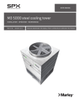
/ Marley MD Cooling Tower /
Engineering Data & Specifications
Marley / MD Cooling Tower / Table of Contents
Engineering Data
Schematic
Support
Outlet Connection
Hoisting Info
Freeze Prevention
Water Quality
6
22
24
25
26
27
Specifications / Base
Base
Thermal Performance
Performance Warranty
Design Loading
Construction
Mechanical Equipment
Fill, Louvers and Drift Eliminators
Hot Water Distribution System
Casing and Fan Guard
Access
Collection Basin
Warranty
28
28
28
29
29
29
31
31
31
31
32
32
Specifications / Options
Stainless Steel Options
Stainless Steel Collection Basin
All Stainless Steel Cooling Tower
33
33
Convenience and Safety Options
Mechanical Access Platform
Ladder Extension
Ladder Safety Cage
34
34
34
Control Options
Fan Motor Starter Control Panel
Vibration Limit Switch
Basin Heater
Fan Motor Variable Speed Drive
35
36
36
36
Miscellaneous Options
Equalizer Flume Weir Gates
Premium Efficiency Motor
Sound Control
38
38
39
Marley / MD Cooling Tower /
■ Air Movement Package
High efficiency fan—wide-chord design for maximum efficiency at low fan tip speeds
Eased inlet fan cylinder—ensures full area, low turbulent airflow through the cylinder
Spherical roller bearings are rated at an L10 life of 100,000 hours
TEFC Fan Motor—1.15 service factor, variable torque, and specially insulated for cooling tower duty
The MD Series air movement package including the structural support—guaranteed against failure for a
period of five full years. The motor is warranted separately by the motor manufacturer
■ Water Distribution System
Pressurized spray system distributes water evenly over the fill
Low-clog polypropylene nozzles—delivers precise distribution of water over the fill area
Marley MC thermoformed PVC film fill assembled into packs for ease of removal and cleaning
Marley XCEL drift eliminators—limit drift losses to no more than .001% of the design GPM flow rate
■ Structure
Induced-draft, counterflow design may require less plan area than crossflow towers typically use
Series 300 stainless steel, 316 stainless steel or heavy mill galvanized steel construction
Factory assembled—ensures final field installation will be hassle-free
Triple-pass PVC inlet louvers—limits splash-out and eliminate sunlight from entering the collection basin
4
Marley / MD Cooling Tower /
MD
towers are galvanized steel, factory
assembled, counterflow cooling towers,
designed to serve air conditioning and refrigeration
systems as well as light to medium industrial process
loads on clean water. The Marley MD evolved from a
factory-assembled concept of towers pioneered by
Marley some 75 years ago, and incorporate all of the
design advancements that our customers have found
valuable. MD towers represent the current state of the
art in this cooling tower category.
The specifications portion of this publication not
only relates the language to use in describing an
appropriate MD cooling tower—but also defines why
certain items and features are important enough to
specify with the intention of insisting upon compliance
by all bidders. The left hand column of pages 28
through 39 provides appropriate text for the various
specification paragraphs, whereas the right hand
5
column comments on the meaning of the subject
matter and explains its value.
Pages 33 through 39 indicate those paragraphs
which will result in the purchase of a basic cooling
tower—one that accomplishes the specified thermal
performance, but which will lack many operation—and
maintenance-enhancing accessories and features
that are usually desired by those persons who are
responsible for the continuing operation of the
system of which the cooling tower is part. It will also
incorporate those standard materials which testing and
experience has proven to provide acceptable longevity
in normal operating conditions.
Pages 33 through 39 provide paragraphs intended to
add those features, components, and materials that
will customize the cooling tower to meet the user‘s
requirements.
Marley / MD Cooling Tower / Engineering Data : Schematic
6
MD5008 SINGLE CELL
Use this data for preliminary layouts only.
Obtain current drawing from your Marley sales
representative.
2578
The UPDATE web-based selection software
—available at spxcooling.com—provides
MD model recommendations based on
customer's specific design requirements.
CL
PLAN
35
2731
569
140
8" INLET
MOTOR
H
A
SIDE ELEVATION
END ELEVATION
Marley / MD Cooling Tower / Engineering Data : Schematic
7
MD5008 SINGLE CELL
note 3
Motor
kW
dBA
1.5m from air
inlet face
MD5008MAC1L
165
5.5
80
MD5008MLC1L
163
5.5
79
MD5008NAC1L
179
7.5
81
MD5008NLC1L
179
7.5
79
MD5008PAC1L
202
11
81
MD5008PLC1L
202
11
80
MD5008QAC1L
216
15
81
MD5008QLC1L
216
15
80
MD5008MAD1L
180
5.5
80
MD5008MLD1L
177
5.5
79
MD5008NAD1L
197
7.5
81
Model
Nominal Tons
note 2
MD5008NLD1L
196
7.5
79
MD5008PAD1L
223
11
81
MD5008PLD1L
223
11
80
MD5008QAD1L
239
15
81
MD5008QLD1L
238
15
80
MD5008MAF1L
189
5.5
80
MD5008MLF1L
185
5.5
79
MD5008NAF1L
207
7.5
81
MD5008NLF1L
206
7.5
79
MD5008PAF1L
234
11
81
MD5008PLF1L
234
11
80
MD5008QAF1L
255
15
81
MD5008QLF1L
257
15
80
Dimensions
Design
Operating
Weight
kg
Shipping Weight
kg
Weight/Cell
Heaviest
Section
3051
1702
891
2486
3176
1828
936
2791
3302
1953
1062
H
A
3294
2181
3599
3904
NOTE
1 Use this bulletin for preliminary layouts only. Obtain
current drawings from your Marley sales representative. All
table data is per cell.
2 Last two characters of the model number indicate number of
cells and cell configuration.
3 Nominal tons are based upon 35°C HW, 29.5°C CW, 25.5°C
WB and .68 m3/hr per ton. The Marley UPDATE web-based
selection software provides MD model recommendations
based on specific design requirements.
4 Standard overflow is a 3" dia. M connection located on the
side of the collection basin. Makeup water connection is 2" dia.
M connection located on the side of the tower. A 3" M drain
connection is located on the side of the collection basin.
Marley / MD Cooling Tower / Engineering Data : Schematic
8
MD5008 MULTICELL
Use this data for preliminary layouts only.
Obtain current drawing from your Marley sales
representative.
2578
CL
The UPDATE web-based selection software
—available at spxcooling.com—provides
MD model recommendations based on
customer's specific design requirements.
CL
PLAN
2371
35
569
2794
140
8" INLET
MOTOR
H
INSTALLED
HEIGHT
A
SIDE ELEVATION
END ELEVATION
Marley / MD Cooling Tower / Engineering Data : Schematic
9
MD5008 MULTICELL
note 3
Motor
kW
dBA
1.5m from air
inlet face
MD5008MAC2L
165
5.5
80
MD5008MLC2L
165
5.5
79
MD5008NAC2L
179
7.5
81
MD5008NLC2L
179
7.5
79
MD5008PAC2L
202
11
81
MD5008PLC2L
202
11
80
MD5008QAC2L
217
15
81
MD5008QLC2L
217
15
80
MD5008MAD2L
180
5.5
80
MD5008MLD2L
180
5.5
79
MD5008NAD2L
196
7.5
81
Model
Nominal Tons
note 2
MD5008NLD2L
196
7.5
79
MD5008PAD2L
222
11
81
MD5008PLD2L
222
11
80
MD5008QAD2L
239
15
81
MD5008QLD2L
239
15
80
MD5008MAF2L
188
5.5
80
MD5008MLF2L
188
5.5
79
MD5008NAF2L
205
7.5
81
MD5008NLF2L
205
7.5
79
MD5008PAF2L
234
11
81
MD5008PLF2L
234
11
80
MD5008QAF2L
251
15
81
MD5008QLF2L
251
15
80
Dimensions
Design
Operating
Weight
kg
Shipping Weight
kg
Weight/Cell
Heaviest
Section
3072
1723
891
2718
3197
1848
957
3023
3323
1974
1083
H
A
3526
2413
3831
4136
NOTE
1 Use this bulletin for preliminary layouts only. Obtain
current drawings from your Marley sales representative. All
table data is per cell.
2 Last two characters of the model number indicate number of
cells and cell configuration. Change as appropriate for your
selection.
3 Nominal tons are based upon 35°C HW, 29.5°C CW, 25.5°C
WB and .68 m3/hr per ton. The Marley UPDATE web-based
selection software provides MD model recommendations
based on specific design requirements.
4 Standard overflow is a 3" dia. M connection located on the
side of the collection basin. Makeup water connection is 2"
dia. M connection located on the side of the tower. A 3" M
drain connection is located on the side of the collection basin.
Marley / MD Cooling Tower / Engineering Data : Schematic
10
MD5010 SINGLE CELL
Use this data for preliminary layouts only.
Obtain current drawing from your Marley sales
representative.
2578
The UPDATE web-based selection software
—available at spxcooling.com—provides
MD model recommendations based on
customer's specific design requirements.
CL
PLAN
35
3651
569
140
8" INLET
MOTOR
H
A
SIDE ELEVATION
END ELEVATION
Marley / MD Cooling Tower / Engineering Data : Schematic
11
MD5010 SINGLE CELL
note 3
Motor
kW
dBA
1.5m from air
inlet face
MD5010PAC1L
248
11
81
MD5010PLC1L
249
11
80
MD5010QAC1L
269
15
81
MD5010QLC1L
270
15
80
MD5010RAC1L
286
18.5
81
MD5010RLC1L
289
18.5
80
MD5010PAD1L
279
11
81
MD5010PLD1L
280
11
80
MD5010QAD1L
304
15
81
MD5010QLD1L
305
15
80
MD5010RAD1L
325
18.5
81
MD5010RLD1L
329
18.5
80
Model
Nominal Tons
note 2
MD5010PAF1L
293
11
81
MD5010PLF1L
294
11
80
MD5010QAF1L
317
15
81
MD5010QLF1L
318
15
80
MD5010RAF1L
341
18.5
81
MD5010RLF1L
346
18.5
80
MD5010SAF1L
360
22
81
MD5010SLF1L
362
22
81
Dimensions
Design
Operating
Weight
kg
Shipping Weight
kg
Weight/Cell
Heaviest
Section
3883
2079
1052
2604
4046
2242
1190
2909
4234
2430
1353
H
A
3412
2299
3717
4021
NOTE
1 Use this bulletin for preliminary layouts only. Obtain current
drawings from your Marley sales representative. All table data
is per cell.
2 Last two characters of the model number indicate number of
cells and cell configuration.
3 Nominal tons are based upon 35°C HW, 29.5°C CW, 25.5°C
WB and .68 m3/hr per ton. The Marley UPDATE web-based
selection software provides MD model recommendations
based on specific design requirements.
4 Standard overflow is a 3" dia. M connection located on the
side of the collection basin. Makeup water connection is 2" dia.
M connection located on the side of the tower. A 3" M drain
connection is located on the side of the collection basin.
Marley / MD Cooling Tower / Engineering Data : Schematic
12
MD5010 MULTICELL
Use this data for preliminary layouts only.
Obtain current drawing from your Marley sales
representative.
2578
CL
The UPDATE web-based selection software
—available at spxcooling.com—provides
MD model recommendations based on
customer's specific design requirements.
CL
PLAN
3651
35
3715
569
140
8" INLET
MOTOR
H
A
SIDE ELEVATION
END ELEVATION
Marley / MD Cooling Tower / Engineering Data : Schematic
13
MD5010 MULTICELL
note 3
Motor
kW
dBA
1.5m from air
inlet face
MD5010PAC2L
248
11
81
MD5010PLC2L
249
11
80
MD5010QAC2L
269
15
81
MD5010QLC2L
270
15
80
MD5010RAC2L
286
18.5
81
MD5010RLC2L
289
18.5
80
Model
Nominal Tons
note 2
MD5010PAD2L
279
11
81
MD5010PLD2L
280
11
80
MD5010QAD2L
304
15
81
MD5010QLD2L
305
15
80
MD5010RAD2L
325
18.5
81
MD5010RLD2L
329
18.5
80
MD5010PAF2L
293
11
81
MD5010PLF2L
294
11
80
MD5010QAF2L
317
15
81
MD5010QLF2L
318
15
80
MD5010RAF2L
341
18.5
81
MD5010RLF2L
346
18.5
80
MD5010SAF2L
360
22
81
MD5010SLF2L
362
22
81
Dimensions
Design
Operating
Weight
kg
Shipping Weight
kg
Weight/Cell
Heaviest
Section
3906
2102
1052
2820
4069
2265
1213
3124
4256
2453
1376
H
A
3628
2515
3932
4237
NOTE
1 Use this bulletin for preliminary layouts only. Obtain current
drawings from your Marley sales representative. All table data
is per cell.
2 Last two characters of the model number indicate number of
cells and cell configuration. Change as appropriate for your
selection.
3 Nominal tons are based upon 35°C HW, 29.5°C CW, 25.5°C
WB and .68 m3/hr per ton. The Marley UPDATE web-based
selection software provides MD model recommendations
based on specific design requirements.
4 Standard overflow is a 3" dia. M connection located on the
side of the collection basin. Makeup water connection is 2" dia.
M connection located on the side of the tower. A 3" M drain
connection is located on the side of the collection basin.
Marley / MD Cooling Tower / Engineering Data : Schematic
14
MD5016 SINGLE CELL
Use this data for preliminary layouts only.
Obtain current drawing from your Marley sales
representative.
3607
The UPDATE web-based selection software
—available at spxcooling.com—provides
MD model recommendations based on
customer's specific design requirements.
CL
PLAN
3651
35
153
ACCESS
8" INLET
H
A
SIDE ELEVATION
END ELEVATION
Marley / MD Cooling Tower / Engineering Data : Schematic
15
MD5016 SINGLE CELL
note 3
Motor
kW
dBA
1.5m from air
inlet face
MD5016PAC1L
317
11
79
MD5016PLC1L
320
11
78
MD5016QAC1L
345
15
80
Model
Nominal Tons
note 2
MD5016QLC1L
348
15
79
MD5016RAC1L
369
18.5
80
MD5016RLC1L
372
18.5
79
MD5016SAC1L
390
22
81
MD5016SLC1L
394
22
80
MD5016PAD1L
350
11
79
MD5016PLD1L
353
11
78
MD5016QAD1L
383
15
80
MD5016QLD1L
384
15
79
MD5016RAD1L
410
18.5
80
MD5016RLD1L
412
18.5
79
MD5016SAD1L
436
22
81
MD5016SLD1L
437
22
80
MD5016TAD1L
475
30
82
MD5016TLD1L
471
30
80
MD5016PAF1L
368
11
79
MD5016PLF1L
370
11
78
MD5016QAF1L
403
15
80
MD5016QLF1L
401
15
79
MD5016RAF1L
431
18.5
80
MD5016RLF1L
431
18.5
79
MD5016SAF1L
460
22
81
MD5016SLF1L
459
22
80
MD5016TAF1L
500
30
82
MD5016TLF1L
493
30
80
Dimensions
Design
Operating
Weight
kg
Shipping Weight
kg
Weight/Cell
Heaviest
Section
5805
3225
1710
2834
6089
3508
1763
3139
6320
3739
1977
H
A
4239
2529
4544
4848
NOTE
1 Use this bulletin for preliminary layouts only. Obtain current
drawings from your Marley sales representative. All table data
is per cell.
2 Last two characters of the model number indicate number of
cells and cell configuration.
3 Nominal tons are based upon 35°C HW, 29.5°C CW, 25.5°C
WB and .68 m3/hr per ton. The Marley UPDATE web-based
selection software provides MD model recommendations
based on specific design requirements.
4 Standard overflow is a 3" dia. M connection located on the
side of the collection basin. Makeup water connection is 2" dia.
M connection located on the side of the tower. A 3" M drain
connection is located on the side of the collection basin.
Marley / MD Cooling Tower / Engineering Data : Schematic
16
MD5016 TWO OR THREE CELL
Use this data for preliminary layouts only.
Obtain current drawing from your Marley sales
representative.
3607
CL
The UPDATE web-based selection software
—available at spxcooling.com—provides
MD model recommendations based on
customer's specific design requirements.
CL
PLAN
3651
35
3715
153
ACCESS
8" INLET
H
A
SIDE ELEVATION
END ELEVATION
Marley / MD Cooling Tower / Engineering Data : Schematic
17
MD5016 TWO OR THREE CELL
note 3
Motor
kW
dBA
1.5m from air
inlet face
MD5016PAC2L
317
11
79
MD5016PLC2L
320
11
78
MD5016QAC2L
345
15
80
Model
Nominal Tons
note 2
MD5016QLC2L
348
15
79
MD5016RAC2L
369
18.5
80
MD5016RLC2L
372
18.5
79
MD5016SAC2L
390
22
81
MD5016SLC2L
394
22
80
MD5016PAD2L
350
11
79
MD5016PLD2L
353
11
78
MD5016QAD2L
383
15
80
MD5016QLD2L
384
15
79
MD5016RAD2L
410
18.5
80
MD5016RLD2L
412
18.5
79
MD5016SAD2L
436
22
81
MD5016SLD2L
437
22
80
MD5016TAD2L
475
30
82
MD5016TLD2L
471
30
80
MD5016PAF2L
368
11
79
MD5016PLF2L
370
11
78
MD5016QAF2L
403
15
80
MD5016QLF2L
401
15
79
MD5016RAF2L
431
18.5
80
MD5016RLF2L
431
18.5
79
MD5016SAF2L
460
22
81
MD5016SLF2L
459
22
80
MD5016TAF2L
500
30
82
MD5016TLF2L
493
30
80
Dimensions
Design
Operating
Weight
kg
Shipping Weight
kg
Weight/Cell
Heaviest
Section
5860
3279
1710
3142
6143
3563
1800
3447
6375
3794
2032
H
A
4547
2837
4852
5156
NOTE
1 Use this bulletin for preliminary layouts only. Obtain current
drawings from your Marley sales representative. All table data
is per cell.
2 Last two characters of the model number indicate number of
cells and cell configuration. Change as appropriate for your
selection.
3 Nominal tons are based upon 35°C HW, 29.5°C CW, 25.5°C
WB and .68 m3/hr per ton. The Marley UPDATE web-based
selection software provides MD model recommendations
based on specific design requirements.
4 Standard overflow is a 3" dia. M connection located on the
side of the collection basin. Makeup water connection is 2" dia.
M connection located on the side of the tower. A 3" M drain
connection is located on the side of the collection basin.
Marley / MD Cooling Tower / Engineering Data : Schematic
18
MD5016 FOUR OR MORE CELLS
Use this data for preliminary layouts only.
Obtain current drawing from your Marley sales
representative.
3607
CL
The UPDATE web-based selection software
—available at spxcooling.com—provides
MD model recommendations based on
customer's specific design requirements.
CL
PLAN
3651
35
3715
153
ACCESS
8" INLET
H
A
SIDE ELEVATION
END ELEVATION
Marley / MD Cooling Tower / Engineering Data : Schematic
19
MD5016 FOUR OR MORE CELLS
note 3
Motor
kW
dBA
1.5m from air
inlet face
317
11
79
Model
Nominal Tons
note 2
MD5016PAC4L
MD5016PLC4L
320
11
78
MD5016QAC4L
345
15
80
MD5016QLC4L
348
15
79
MD5016RAC4L
369
18.5
80
MD5016RLC4L
372
18.5
79
MD5016SAC4L
390
22
81
MD5016SLC4L
394
22
80
MD5016PAD4L
350
11
79
MD5016PLD4L
353
11
78
MD5016QAD4L
383
15
80
MD5016QLD4L
384
15
79
MD5016RAD4L
410
18.5
80
MD5016RLD4L
412
18.5
79
MD5016SAD4L
436
22
81
MD5016SLD4L
437
22
80
MD5016TAD4L
475
30
82
MD5016TLD4L
471
30
80
MD5016PAF4L
368
11
79
MD5016PLF4L
370
11
78
MD5016QAF4L
403
15
80
MD5016QLF4L
401
15
79
MD5016RAF4L
431
18.5
80
MD5016RLF4L
431
18.5
79
MD5016SAF4L
460
22
81
MD5016SLF4L
459
22
80
MD5016TAF4L
500
30
82
MD5016TLF4L
493
30
80
Dimensions
Design
Operating
Weight
kg
Shipping Weight
kg
Weight/Cell
Heaviest
Section
5933
3353
1710
3396
6217
3636
1874
3701
6448
3868
2105
H
A
4801
3091
5106
5410
NOTE
1 Use this bulletin for preliminary layouts only. Obtain current
drawings from your Marley sales representative. All table data
is per cell.
2 Last two characters of the model number indicate number of
cells and cell configuration. Change as appropriate for your
selection.
3 Nominal tons are based upon 35°C HW, 29.5°C CW, 25.5°C
WB and .68 m3/hr per ton. The Marley UPDATE web-based
selection software provides MD model recommendations
based on specific design requirements.
4 Standard overflow is a 3" dia. M connection located on the
side of the collection basin. Makeup water connection is 2" dia.
M connection located on the side of the tower. A 3" M drain
connection is located on the side of the collection basin.
Marley / MD Cooling Tower / Engineering Data : Schematic
20
MD5016 FOUR CELL QUAD
Use this data for preliminary layouts only.
Obtain current drawing from your Marley sales
representative.
The UPDATE web-based selection software
—available at spxcooling.com—provides
MD model recommendations based on
customer's specific design requirements.
7312
CL
CL
PLAN
35
7366
3715
153
ACCESS
8" INLET
H
A
SIDE ELEVATION
END ELEVATION
Marley / MD Cooling Tower / Engineering Data : Schematic
21
MD5016 FOUR CELL QUAD
note 3
Motor
kW
dBA
1.5m from air
inlet face
MD5016PAC4B
317
11
79
MD5016PLC4B
320
11
78
MD5016QAC4B
345
15
80
MD5016QLC4B
348
15
79
MD5016RAC4B
369
18.5
80
MD5016RLC4B
372
18.5
79
MD5016SAC4B
390
22
81
Model
Nominal Tons
note 2
MD5016SLC4B
394
22
80
MD5016PAD4B
350
11
79
MD5016PLD4B
353
11
78
MD5016QAD4B
383
15
80
MD5016QLD4B
384
15
79
MD5016RAD4B
410
18.5
80
MD5016RLD4B
412
18.5
79
MD5016SAD4B
436
22
81
MD5016SLD4B
437
22
80
MD5016TAD4B
475
30
82
MD5016TLD4B
471
30
80
MD5016PAF4B
368
11
79
MD5016PLF4B
370
11
78
MD5016QAF4B
403
15
80
MD5016QLF4B
401
15
79
MD5016RAF4B
431
18.5
80
MD5016RLF4B
431
18.5
79
MD5016SAF4B
460
22
81
MD5016SLF4B
459
22
80
MD5016TAF4B
500
30
82
MD5016TLF4B
493
30
80
Dimensions
Design
Operating
Weight
kg
Shipping Weight
kg
Weight/Cell
Heaviest
Section
5933
3353
1710
3396
6217
3636
1874
3701
6448
3868
2105
H
A
4801
3091
5106
5410
NOTE
1 Use this bulletin for preliminary layouts only. Obtain current
drawings from your Marley sales representative. All table data
is per cell.
2 Nominal tons are based upon 35°C HW, 29.5°C CW, 25.5°C
WB and .68 m3/hr per ton. The Marley UPDATE web-based
selection software provides MD model recommendations
based on specific design requirements.
3 Standard overflow is a 3" dia. M connection located on the
side of the collection basin. Makeup water connection is 2" dia.
M connection located on the side of the tower. A 3" M drain
connection is located on the side of the collection basin.
Marley / MD Cooling Tower / Engineering Data: Support
22
L
OVERALL OF BASIN
E
D
E
ANCHORCL
BOLT
CL ANCHOR
BOLT
A
ANCHOR CL
BOLT
21
TOWER
COLLECTION
BASIN
W OVERALL WIDTH OF BASIN
HOLES FOR
M16 ANCHOR
BOLTS 4 REQD
21
SUPPORT
BY OTHERS
C
NORMAL
GAUGE
TOWER COLLECTION
BASIN
CL ANCHOR
BOLT
VIEW A
21
SUPPORTING STEEL
SINGLE CELL
Dimensions
Model
Design
Operating
Weight
Design
Operating Load
at support beam
kg/m
W
L
C
D
E
F
MD5008__C
2578
2731
2537
2629
51
165
3072
563
MD5008__D
2578
2731
2537
2629
51
165
3197
586
MD5008__F
2578
2731
2537
2629
51
165
3323
609
MD5010__C
2578
3651
2537
3550
51
165
3906
549
MD5010__D
2578
3651
2537
3550
51
165
4069
568
MD5010__F
2578
3651
2537
3550
51
165
4256
592
MD5016__C
3607
3651
3566
3397
127
318
5860
908
MD5016__D
3607
3651
3566
3397
127
318
6143
951
MD5016__F
3607
3651
3566
3397
127
318
6375
982
per cell
kg
Marley / MD Cooling Tower / Engineering Data: Support
23
OVERALL LENGTH OF BASIN
E
D
CL ANCHOR
BOLT
E
ANCHOR CL
BOLT
A
ANCHOR CL
BOLT
21
F
ANCHOR CL CL ANCHOR
BOLT
BOLT
W OVERALL WIDTH OF BASIN
HOLES FOR
M16 ANCHOR
BOLTS 4/CELL
CLANCHOR
BOLT
C
TOWER COLLECTION
BASIN
21
SUPPORTING STEEL
MULTICELL
NOTE
1 Use this bulletin for preliminary layouts only. Obtain current
drawings from your Marley sales representative for final design.
2 Purchaser to provide tower support complete with holes and
anchor bolts. Do not use studs! Anchor points must be framed
flush and level at top.
3 Design operating weight occurs with collection basin full to
overflow level. Actual operating weight varies with m3/hr and
piping scheme.
4 Tower may be placed on a flat concrete slab. Side outlet and
optional side drain and overflow must be specified.
Marley / MD Cooling Tower / Engineering Data : Outlet Connection
MAKEUP
MAKEUP
2" NPTM
MECHANICAL
COUPLING GROOVE
ALTERNATE LOCATION
SUCTION HOOD
WELDING
BEVEL
C
D
24
REMOVABLE
TRASH SCREEN
A
PUMP
SUCTION
CL TOWER
OVERFLOW
B
89
3" NPTF
23
DRAIN
SUCTION SECTION
3" NPTF
SIDE-OUTLET SUCTION CONNECTION
Dimensions
MAKEUP
Model
2" NPTM
SLOPING
BASIN FLOOR
Suction
Diameter
A
B
C
D
6"
8"
10"
6"
8"
10"
6"
8"
10"
12"
—
191
—
—
191
—
—
191
216
—
493
493
493
477
477
477
477
477
477
477
588
588
588
588
588
588
639
639
639
639
305
305
305
305
305
305
331
331
331
331
MD5008
C
D
A
89
MD5010
OVERFLOW
496
3" NPTF
DRAIN
PUMP
SUCTION
MD5016
878
3" NPTF
END-OUTLET SUCTION CONNECTION
MAKEUP
MAKEUP
2" NPTM
ALTERNATE LOCATION
CL SUMP
C
OVERFLOW
D
ANTI-VOTEX PLATE
CL OUTLET
WITH SCREEN OR
REMOVABLE
TRASH SCREEN
CL TOWER
3" NPTF
DRAIN
B
89
502
3" NPTF
OUTLET PIPING
DRAIN
SUMP FACE MAY
BE ROTATED 90° OR 180°
BY OTHERS
11/2" NPTF
BOTTOM OUTLET
CONNECTION
153
SIDE-OUTLET SUMP CONNECTION
SUMP SECTION
Maximum m3/hr per Outlet
Outlet
Diameter
Side or End Suction
pump flow
Sump
pump flow
without
anti-vortex plate
Sump
pump flow
with anti-vortex plate or
gravity flow
with or without
anti-vortex plate
Bottom Outlet
pump flow
without
anti-vortex plate
Bottom Outlet
plump flow
with anti-vortex plate or
gravity flow
with or without
anti-vortex plate
MD5008 MD5010 MD5016 MD5008 MD5010 MD5016 MD5008 MD5010 MD5016 MD5008 MD5010 MD5016 MD5008 MD5010 MD5016
6"
8"
10"
12"
259
338
144
144
144
205
205
205
76
355
248
248
248
259
338
355
136
136
136
493
259
338
391
259
338
493
215
215
215
304
142
143
143
259
304
173
173
173
259
338
368
16"
226
226
226
259
338
480
18"
259
286
286
259
338
493
338
355
24"
493
101
14"
20"
493
96
493
338
493
493
Marley / MD Cooling Tower / Engineering Data : Hoisting
25
OFFSET MAY BE REQUIRED
FOR BALANCED LIFT
OFFSET MAY BE REQUIRED
FOR BALANCED LIFT
CENTER OF
TOWER
CENTER OF
TOWER
LIFTING
SLING
LIFTING
SLING
WIDTH
WIDTH
70° MAX
BOTH MODULES
Base Module
Model
Top Module
Width
Sling Length
Minimum
Weight
kg
Width
Sling Length
Minimum
Weight
kg
MD5008
2.6m
3m
1100
2.8m
3m
900
MD5010
2.6m
4m
1350
2.6m
3m
1050
MD5016
3.7m
4m
1650
3.7m
3m
1750
NOTE
1 Hoisting operations can be dangerous and suitable safety
precautions should be taken to protect personnel and the
equipment being hoisted.
2 All hoisting equipment should be certified and comply with
local and national safety regulations.
3 Ensure that slings are of sufficient length so not to impose
bending loads onto the casing—use of spreader bars is
essential.
4 For overhead lifts or where additional safety is required, add
slings beneath the tower unit
Marley / MD Cooling Tower / Engineering Data: Freeze Prevention
When the ambient air temperature falls below 0°C,
the water in a cooling tower can freeze. Marley Technical
Report #H-003 “Operating Cooling Towers in Freezing
Weather” describes how to prevent freezing during
operation. Available at spxcooling.com or ask your Marley
sales representative for a copy.
During shutdown, water collects in the cold water
basin and may freeze solid. You can prevent freezing by
adding heat to the water left in the tower—or, you can
drain the tower and all exposed pipework at shutdown.
Electric Basin Heaters
An automatic basin water heater system is available
consisting of the following components:
• Standard weatherproof (IP55) enclosure, rating
depending on model and minimum expected winter
temperature.
• Ratings are in kW for specified ambient temperature.
For lower ambient temperatures refer to SPX
engineering for advice.
• Standard electircal supply is 380/415 V 3ph (220/240V 1
ph available as extra cost option).
• Heater has an integral thermostat, set point nominally
3°C but adjustable to suit operating requirements.
Heater components are normally shipped separately
for installation by others.
Note: any exposed piping that is still filled with water
at shutdown—including the makeup water line—should
be electrically traced and insulated (by others).
Indoor Storage Tank
With this type of system, water flows from an indoor
tank, through the load system, and back to the tower,
where it is cooled. The cooled water flows by gravity
from the tower to the tank located in a heated space. At
shutdown, all exposed water drains into the tank, where it
is safe from freezing.
The amount of water needed to successfully operate
the system depends on the tower size and GPM and
on the volume of water contained in the piping system
to and from the tower. You must select a tank large
enough to contain those combined volumes—plus a level
sufficient to maintain a flooded suction on your pump.
Control makeup water according to the level where the
tank stabilizes during operation.
26
Marley / MD Cooling Tower / Engineering Data: Water Quality
The MD cooling tower can be a very effective air
washer. Atmospheric dust able to pass through the
relatively small louver openings will enter the recirculating
water system. Increased concentrations can intensify
systems maintenance by clogging screens and strainers—
and smaller particulates can coat system heat transfer
surfaces. In areas of low flow velocity—such as the
collection basin—sedimentary deposits can provide a
breeding ground for bacteria.
In areas prone to dust and sedimentation, you should
consider installing some means for keeping the collection
basin clean. Typical devices include side stream filters and
a variety of filtration media.
CAUTION
The MD cooling tower must be located at such
distance and direction to avoid the possibility
of contaminated discharge air being drawn into
building fresh air intake ducts. The purchaser should
obtain the services of a Licensed professional
Engineer or Registered Architect to certify that the
location of the cooling tower is in compliance with
applicable air pollution, fire and clean air codes.
Water Treatment
Blowdown
Blowdown or Bleedoff is the continuous removal of
a small portion of the water from the open recirculating
system. Blowdown is used to prevent the dissolved solids
from concentrating to the point where they will form
scale. The amount of blowdown required depends on
the cooling range—the difference between the hot and
cold water temperatures of the closed circuit— and the
composition of the makeup water.
To control the buildup of dissolved solids resulting
from water evaporation, as well as airborne impurities and
biological contaminants including Legionella, an effective
consistent water treatment program is required. Simple
blowdown may be adequate to control corrosion and
scale, but biological contamination can only be controlled
with biocides.
An acceptable water treatment program must be
compatible with the variety of materials incorporated in
a cooling tower—ideally the pH of the recirculating water
should fall between 6.5 and 9.0. Batch feeding of the
chemicals directly into the cooling tower is not a good
practice since localized damage to the cooling tower
is possible. Specific startup instructions and additional
water quality recommendations can be found in the MD
Cooling Tower User Manual which accompanies the
cooling tower and also is available at spxcooling.com.
27
Marley / MD Cooling Tower / Specifications: Base
Specifications
1.0
Base:
1.1
Furnish and install an induced-draft,
counterflow-type, factory assembled,
film fill, industrial duty, cooling tower.
Unit shall consist of _____ cell(s), as
shown on plans. The limiting overall
dimensions of the tower shall be _____
wide, _____ long, and _____ high. Total
operating power of all fans shall not
exceed _____ kW, consisting of_____
@ _____ kW motor(s). Tower shall be
Marley Model _____________________.
2.0
Thermal Performance:
2.1 The tower shall be capable of cooling _____ m3/hr of water from ____
°C to _____ °C at a design entering
air wet-bulb temperature of _____ °C.
The thermal performance rating shall
be Certified by the Cooling Technology
Institute. Tower shall comply with all
ASHRAE 90.1 standards.
3.0
Performance Warranty:
3.1
CTI Certification notwithstanding, the
cooling tower manufacturer shall guarantee that the cooling tower supplied
will meet the specified performance
conditions when the tower is installed
as shown on the plans. If, because of
a suspected thermal performance deficiency, the owner chooses to conduct
an on-site thermal performance test
under the supervision of a qualified,
disinterested third party in accordance
with CTI, ASME or other applicable
standards during the first year of operation; and if the tower fails to perform
within the limits of test tolerance; then
the cooling tower manufacturer will
pay for the cost of the test and will
make such corrections as are appropriate and agreeable to the owner to
compensate for the performance deficiency.
Specification Value
■ Your specification base establishes the type, configuration, base material, and physical limitations of the cooling tower to be quoted. During the
planning and layout stages of your project, you will have focused your
attention on a cooling tower selection that fits your space allotment, and
whose power usage is acceptable. Limitations on physical size and total
operating horsepower avoid the introduction of unforeseen operational
and site-related influences. Specifying the number of cells, and the maximum fan hp/cell will work to your advantage.
You are specifying a counterflow tower, which is a type noted—and usually specified—for its economical use of plan area on projects where
the required thermal performance is very difficult. It effectively replaces
most makes of older towers—both forced-draft and induced-draft—without major redesign of the existing site.
■ CTI
Certification means that the cooling
tower has been tested under operating conditions and found to perform as
rated by the manufacturer under those
circumstances. It assures the buyer that
the tower is not intentionally or inadvertently undersized by the manufacturer.
■ However,
CTI certification alone is not sufficient to assure you that the
cooling tower will perform satisfactorily in your situation. Certification
is established under relatively controlled conditions, and cooling towers
seldom operate under such ideal circumstances. They are affected by
nearby structures, machinery, enclosures, effluent from other sources,
etc. Responsible and knowledgeable bidders will take such site-specific
effects into consideration in selecting the cooling tower—but the specifier must insist by the written specification that the designer/manufacturer guarantee this “real world” performance. Any reluctance on the
part of the bidder should cause you some concern.
28
Marley / MD Cooling Tower / Specifications: Base
29
Specification Value
Specifications
4.0
Design Loading:
4.1
The tower and its components shall be
designed to withstand a wind load of
1.44kPa. The cooling tower shall be designed to withstand shipping and hoisting loads of 2g horizontal or 3g vertical.
Guardrails, where specified shall be
capable of withstanding a 890N concentrated live load in any direction and
shall be designed in accordance with
OSHA guidelines.
5.0
Construction:
5.1
Except where otherwise specified,
all components of the cooling tower
shall be fabricated of heavy-gauge
steel, protected against corrosion by
EN10142:2000 grade Z600 galvanizing. After passivation of the galvanized
steel (8 weeks at pH 7-8, and calcium
hardness and alkalinity at 100-300
mg/L each), the cooling tower shall be
capable of withstanding water having a
pH of 6.5 to 9.0; a chloride content up
to 500 mg/L as NaCl (300 mg/L as Cl-);
a sulfate content (as SO4) up to 250
mg/L; a calcium content (as CaCO3)
up to 500 mg/L; silica (as SiO2) up to
150 mg/L; and design operating ranges
up to 10°C. The circulating water shall
contain no oil, grease, fatty acids, or
organic solvents.
5.2
The specifications, as written, are
intended to indicate those materials
that will be capable of withstanding
the above water quality in continuing
service, as well as the loads described
in paragraph 4.1. They are to be regarded as minimum requirements. Where
component materials unique to individual tower designs are not specified,
the manufacturers shall take the above
water quality and load carrying capabilities into account in the selection of
their materials of manufacture.
6.0
Mechanical Equipment:
6.1
Fan(s) shall be propeller-type, incorporating heavy aluminum alloy blades and
electrogalvanized hubs. Blades shall be
individually adjustable and both statically and dynamically balanced. Fan(s)
➠
■ The indicated design values are the minimum allowables under
accepted design standards. They give you assurance that the cooling tower can be shipped, handled, hoisted—and ultimately operated in a normal cooling tower environment. Most MD models will
withstand significantly higher wind and seismic loads. If your geographic location dictates higher wind load or seismic load values,
please make the appropriate changes, after discussion with your
Marley sales representative.
■ In
the history of cooling towers, no other coating for carbon steel
has exhibited the success and longevity of galvanization in exposure to the normal cooling tower water quality defined at left. No
paints or electrostatically-applied coatings, however exotic they
may be, can approach galvanization's history of success.
If extended longevity of the cooling tower is required—or unusually
harsh operating conditions are expected—consider specifying stainless steel as either the base construction material, or the material
utilized for specific components of your choice. See Stainless Steel
Options on page 16.
■ Propeller-type
fans require only half the operating hp of blower-type
fans. However, they should be readily adjustable to permit compensation for jobsite conditions. The fans of one manufacturer require
the purchase of special positioners for each increment of fan blade
pitch. The Marley Power Belt drive system features all-aluminum
➠
Marley / MD Cooling Tower / Specifications: Base
Specifications
6.2
6.3
shall be driven through a one-piece
multi-groove, solid back V-type belt,
sheaves (pulleys), and tapered roller
bearings. Bearings shall be rated at an
L10 life of 100,000 hours, or greater.
Both motor and fan sheaves (pulleys)
shall be all cast aluminum to prevent
premature corrosion.
Motor(s) shall be ____ kW maximum,
TEFC, variable torque, inverter duty
and specially insulated for cooling
tower duty. Speed and electrical characteristics shall be ______ RPM, singlewinding, ___ phase, ____ hertz, ____
volts. Motor nameplate power shall
not be exceeded at design operation.
TEAO motors are not acceptable.
The complete mechanical equipment
assembly for each cell shall be supported by a rigid, hot-dip galvanized steel
structural support that resists misalignment between the motor and sheaves
(pulleys). For belt-drive towers with
motors inside the airstream, motors
shall be mounted on an adjustable base
that swivels outside the access door
for maintenance. For belt-drive towers with motors mounted outside the
airstream, a protective cover shall be
mounted over the motor and sheave to
protect it from the weather and prevent
inadvertent contact. The mechanical
equipment assembly shall be warranted
against any failure caused by defects
in materials and workmanship for no
less than five (5) years following the
date of tower shipment. This warranty
shall cover the fan, speed reducer, drive
shaft and couplings, and the mechanical
equipment support. The electric motor
shall carry a manufacturer's warranty of
at least one year. The bearing assemblies and V-belts shall be warranted for
18 months.
Specification Value
sheaves, power band belts and long-life bearings for dependable service.
TEFC motors offer additional benefits over TEAO motors whose only
source of cooling is the flow of air produced by the cooling tower fan.
This air rate is not always ideal due to motor position, blockage, etc.
TEFC ensures the motor will always be cooled properly.
Unless otherwise specified, motor speed will be 1500 RPM in on standard models. Low noise models will use motor speeds appropriate for
the specific model. If you prefer the operating flexibility of two-speed
operation, please specify two-speed, single-winding motors which
offer full and half speeds for maximum energy savings. Incidentally,
two speed motors are a far better choice than separate “pony” motors
which simply double the problems indicated above and induce parasitic
loads during operation for lower than nameplate efficiency.
The value of a 5 year mechanical equipment warranty speaks for
itself. Except for the motor, virtually all of the mechanical equipment
on a Marley tower is designed and manufactured by SPX Cooling
Technologies. Cooling tower vendors who purchase commercial fans,
gear reducers, driveshafts, etc. may require that you deal directly with
those commercial suppliers for warranty satisfaction.
30
Marley / MD Cooling Tower / Specifications: Base
Specifications
7.0
Fill, Louvers and Drift Eliminators:
7.1
Fill shall be cross-corrugated,
counterflow film type, thermoformed
from 0.40mm thick PVC. Fill shall
be assembled into packs for ease of
removal and cleaning. Fill shall be supported on channel sections supported
from the tower structure and have a
flame spread rating less than 25. Drift
eliminators shall be PVC with a minimum of three changes in air direction,
and shall limit drift losses to no more
than 0.001% of the design water flow
rate.
7.2
Air inlet louvers shall be a minimum of
127mm air travel, triple pass PVC to
prevent water splashout and eliminate
sunlight from entering the collection
basin. For ease of service and long
life of louvers, PVC louvers shall be
enclosed in a removable frame that
attaches to the air inlet without tools.
Louvers with less than three changes
in air direction are unacceptable.
8.0
Hot Water Distribution System:
8.1
A pressured spray system shall distribute water evenly over the fill. The
branch arms shall be corrosion resistant PVC with polypropylene spray nozzles attached to the branch arms with
a rubber socket connection for ease of
removal and cleaning. To ensure proper
spray system operation, nozzles shall
seat in branch arms without regard for
direction or alignment.
9.0
Casing and Fan Guard:
9.1
The casing shall be heavy gauge
EN10142:2000 grade Z600 galvanized
steel and shall be capable of withstanding the loads described in paragraph 4.1. Casing panels shall encase
the fill on all four sides of the tower.
The top of the fan cylinder shall be
equipped with a conical, non-sagging,
removable fan guard, fabricated of
welded 5/16" and 7 gauge rods, and
hot dip galvanized after fabrication.
Specification Value
■ Fill
modules can be removed for inspection and cleaning in accordance with local anti legioinella guidelines.
Drift rate varies with design water loading and air rate, as well as
drift eliminator depth and number of directional changes. The indicated rate of 0.001% is easily achievable without premium cost. If a
lower rate is required, please discuss with your Marley sales representative.
■ The combination of PVC piping and polypropylene nozzles is very
resistant to the build-up of scale and slime.
31
Marley / MD Cooling Tower / Specifications: Base
Specifications
Specification Value
10.0 Access:
10.1 A large rectangular access door shall
be located in the plenum on the motor
side of the tower.
11.0 Cold Water Collection Basin:
11.1 The collection basin shall be heavygauge galvanized steel and shall
include the number and type of suction
connections required to accommodate
the out-flow piping system shown on
the plans. Suction connections shall be
equipped with debris screens. A factory installed, float operated, mechanical make-up valve shall be included.
An overflow and drain connection shall
be provided in each cell of the tower.
The basin floor shall slope toward the
drain to allow complete flush out of
debris and silt which may accumulate. Towers of more than one cell
shall include steel flumes for flow and
equalization between cells.
13.0 Warranty:
13.1 The MD cooling tower shall be free
from defects in materials and workmanship for a period of eighteen (18)
months from the date of shipment.
■ The MD tower design offers side-suction as standard. Bottom outlets
may be supplied to accommodate a variety of piping schemes. Unless
so specified, the tower you may be asked to approve may only be available with one type of suction connection requiring you to redesign your
piping layout.
The sloping floor and low-level drain is valuable because it provides a
way to achieve flush-out cleanability.
32
Marley / MD Cooling Tower / Specifications: Options
Specifications
Stainless Steel Options
Stainless Steel Collection Basin:
11.1 Replace paragraph 11.1 with the
following: The collection basin shall
be heavy-gauge Series 300 stainless
steel. Only low-carbon stainless steel
alloys will be accepted in order to
minimize the risk of intergranular corrosion in the weld zones. Basin shall
include the number and type of suction
connections required to accommodate
the out-flow piping system shown on
the plans. Basin suction connections
shall be equipped with debris screens.
A factory installed, float operated,
mechanical make-up valve shall be
included. An overflow and drain connection shall be provided in each cell
of the tower. The basin floor shall slope
toward the drain to allow complete
flush out of debris and silt which may
accumulate.
All Stainless Cooling Tower
5.1
Replace paragraph 5.1 with the
following: Except where otherwise
specified, all components of the cooling tower shall be fabricated of heavygauge, series 300 stainless steel. Only
low-carbon stainless steel alloys will be
accepted in order to minimize the risk
of intergranular corrosion in the weld
zones. The tower shall be capable of
withstanding water having a chloride
content (NaCl) up to 750 mg/L; a sulfate content (SO4) up to 1200 mg/L;
a calcium content (CaCO3) up to 800
mg/L; silica (SiO2) up to 150 mg/L; and
design operating ranges up to 27.8°C.
The circulating water shall contain no
oil, grease, fatty acids, or organic solvents.
Specification Value
■ The cold water basin is the only part of the tower that is subject to
periods of stagnant water, concentrated with treatment chemicals
and customary contaminants. It is also the most expensive and difficult part of any tower to repair or replace. For these reasons, many
customers—particularly those who are replacing older towers—
choose to specify stainless steel cold water basins.
■ For
pure resistance to corrosion—coupled with the capability to
meet stringent fire and building codes—there is no substitute for
stainless steel. No paints or electostatically-applied coatings, however exotic they may be, can match stainless steel's ability to withstand adverse operating conditions.
33
Marley / MD Cooling Tower / Specifications: Options
Specifications
Convenience and Safety Options
Mechanical Access Platform:
10.2 Add the following paragraph in
the Access section: There shall be
a mechanical access platform at the
mechanical access door allowing
access to the mechanical system, drift
eliminators, distribution system and fill.
The platform shall be galvanized steel
bar grating, supported by galvanized
steel framework attached to the tower.
The platform shall be surrounded by
a guardrail, kneerail, and toeboard
designed according to meet local
safety requirements. A ladder shall be
permanently attached to the platform
and to the casing of the tower, rising
from the base of the tower to the top
of the handrail.
■ Periodic
inspection and maintenance of a cooling tower distribution system is fundamental to preserving maximum cooling system efficiency.
All cooling towers—crossflow or counterflow—are subject to clogging
to varying degrees by waterborne contaminants such as pipe scale and
sediment. Therefore, safe and easy access to these components is of
significant value to the operator.
Access can be provided in a number of ways, including portable ladders or scaffolding, but for maximum safety and convenience, a field
installed Marley access platform with guardrails is available to make
this task as safe and user-friendly as possible. Further, its location on
the side of the tower does not add to the height of the unit, preserving
architectural integrity. It also saves the owner time and money, in that
maintenance personnel may devote their time to inspection rather than
searching for ladders or erection of portable scaffolding.
Ladder Extension:
10.2 Add the following to the end of paragraph 10.2: Provide a ladder extension
for connection to the foot of the ladder.
This extension shall be long enough to
rise from the roof (grade) level to the
base of the cooling tower. The installing contractor shall be responsible for
cutting the ladder to length; attaching it
to the foot of the cooling tower ladder;
and anchoring it at its base.
Specification Value
■ Many
cooling towers are installed such that the base of the unit is 60cm
or more above the roof or grade level. This makes it difficult to get up
to the foot of the attached ladder. The ladder extension alleviates this
problem. Marley ladder extensions are available in standard 1.5m and
3.5 lengths.
Ladder Safety Cage:
10.3 Add the following paragraph in the
Access section: A welded aluminum
safety cage shall surround the ladder,
extending from a point approximately
2m above the foot of the ladder to the
top of the handrail.
34
Marley / MD Cooling Tower / Specifications: Options
Specifications
Control Options
Fan Motor Starter Control Panel:
6.4 Add the following paragraph in
the Mechanical Equipment section: Each cell of the cooling tower
shall be equipped with a UL listed
control system in a IP52 or IP56 outdoor enclosure capable of controlling
single-speed or two-speed motors as
required, and designed specifically for
cooling tower applications. The panel
shall include a main fused disconnect or main circuit breaker with an
external operating handle, lockable in
the off position for safety. Across-theline magnetic starters or solid-state
soft-start starters as required shall
be controlled with a thermostatic or
solid-state temperature controller.
Door mounted selector switches shall
be provided to enable automatic or
manual control and wired to meet local
control voltage. If required, control circuit to be wired out to terminal blocks
for field connection to a remote vibration switch, overload trip alarms and
remote temperature control devices.
The temperature controller shall be
adjustable for the required cold-water
temperature. If a thermostatic controller is used it shall be mounted on the
side of the tower with the temperature
sensing bulb installed in the cold water
basin using a suspension mounting
bracket. If a solid-state temperature
controller is used the controller will be
door mounted on the control panel.
The temperature controller will display
two temperatures, one for outgoing
water and the other for set point.
Water temperature input shall be
obtained using a three-wire RTD with
dry well in the outlet water piping and
wired back to the solid-state temperature controller in the control panel.
Specification Value
■ If
it is your opinion that the control system for the cooling tower
be part of the cooling tower manufacturer’s responsibility, we are
in wholehearted agreement with you. Who better to determine the
most efficient mode and manner of a cooling tower’s operation—
and to apply a system most compatible with it—than the designer
and manufacturer of the cooling tower?
Marley variable speed drives are also available for the ultimate in
temperature control, energy management, and mechanical equipment longevity.
35
Marley / MD Cooling Tower / Specifications: Options
Specifications
Vibration Limit Switch:
6.5
Add the following paragraph in the
Mechanical Equipment section: A
single-pole, double-throw vibration limit
switch in a NEMA 4 housing shall be
installed on the mechanical equipment
support for wiring into the fan motor
shutdown circuit. The purpose of this
switch will be to interrupt power to the
motor in the event of excessive vibration. It shall be adjustable for sensitivity, and shall require manual reset.
Specification Value
■ Unless
specified otherwise, a 3171 switch will
be provided. A double-pole, double-throw
model is also available. If purchased in conjunction with the Control System, it is also
factory-wired. The requirement for manual
reset assures that the tower will be visited to
determine the cause of excess vibration.
Basin Heater:
11.2 Add the following paragraph in the
Cold Water Provide an electric immersion heater for each cell of the tower
to prevent freezing of water in the
collection basin during periods of shutdown. The rod type heater is installed
in the side of the cold water basin.
Each heater will include an integral
thermostat, set point nominally 4°C
but adjustable to suit local operating
requirements.
Fan Motor Variable Speed Drive:
6.4 Add the following paragraph in
the Mechanical Equipment section
when VFD is used as a stand alone
system: A complete UL listed Variable
Speed Drive system in a IP52 indoor or
IP56 3R outdoor enclosure shall be provided. The VFD shall use PWM technology with IGBT switching and integrated
bypass design. VFD output switching
shall not cause mechanical issues with
gearbox teeth or drive shafts. The VFD
shall catch a fan spinning in the reverse
direction without tripping. The panel shall
include a main disconnect with short
circuit protection and external operating
handle, lockable in the off position for
safety. The system shall include a solid
state, PI temperature controller to adjust
frequency output of the drive in response
to the tower cold-water temperature.
The temperature of the cold water and
set point shall be displayed on the door
of the control panel. The bypass shall
include a complete magnetic bypass
circuit with capability to isolate the VFD
when in the bypass mode. Transfer to
the bypass mode shall be automatic in
the event of VFD failure or for specific
trip conditions allowing safe transfer
■ The Marley basin heater components described at left represent our recommendation for a reliable automatic system for the prevention of basin
freezing. They are normally shipped separately for installation at the jobsite by the installing contractor. When purchased in conjunction with the
enhanced Control System option, however, they are customarily factorymounted and tested.
Submerged in basin water, in which zinc ions are present, copper
immersion heaters must not be used. Insist upon stainless steel.
The ambient air temperature that you insert in the specifications should
be the lowest 1% level of winter temperature prevalent at site.
■ Marley
VFD drive systems are designed to combine absolute temperature control with ideal energy management. The cooling tower user
selects a cold water temperature and the drive system will vary the
fan speed to maintain that temperature. Precise temperature control is
accomplished with far less stress to the mechanical equipment components. The improved energy management provides fast payback.
36
Marley / MD Cooling Tower / Specifications: Options
Specifications
of utility voltage to the motor. Automatic
bypass with an earth ground condition is
not allowed. The bypass contactor shall be
cycled on and off while operating in bypass,
to maintain the set-point temperature of the
cold water. The drive design shall be operated as a stand- alone system without the
need for a BMS system. Operator controls
shall be mounted on the front of the enclosure and shall consist of start and stop
control, bypass/VFD selector switch, Auto/
Manual selector switch, manual speed control, and solid-state temperature controller.
An emergency bypass selector switch internal to the panel allowing the cooling tower
fan motor to be run at full speed shall be
furnished. To prevent heating problems in
the cooling tower fan motor and to assure
proper gear box lubrication the VFD system
shall de energize the motor once 25%
motor speed is reached and cooling is no
longer required. The VFD shall include deicing logic with auto canceling and adjustable time. Speed in De-Ice mode shall not
exceed 50 % motor speed. The cooling
tower manufacturer shall supply VFD startup assistance. Tower vibration testing
throughout the speed range is required to
identify and lockout any natural frequency
vibration levels which may exceed CTI
guidelines.
6.4 Add the following paragraph in the
Mechanical Equipment section when
VFD is used with customers Building
Management System: A complete UL
listed Variable Speed Drive system in a
IP10 indoor, IP52 indoor or IP14 outdoor
enclosure shall be provided. The VFD shall
use PWM technology with IGBT switching
and integrated bypass design. VFD out put
switching shall not cause mechanical issues
with gearbox teeth or drive shafts. The VFD
shall catch a fan spinning in the reverse
direction without tripping. The panel shall
include a main disconnect with short circuit
protection and external operating handle,
lockable in the off position for safety. The
VFD system shall receive a speed reference signal from the Building Management
System monitoring the tower cold-water
temperature. The bypass shall include a
complete magnetic bypass circuit and with
capability to isolate the VFD when in the
bypass mode. Transfer to the bypass mode
shall be manual in the event of VFD failure.
Operator controls shall be mounted on the
front of the enclosure and shall consist of
Specification Value
37
Marley / MD Cooling Tower / Specifications: Options
Specifications
Specification Value
start and stop control, bypass/VFD selection, Auto/Manual selections, manual
speed control. To prevent heating problems in the cooling tower fan motor and
to assure proper gear reducer lubrication
the VFD system shall de energize the
motor once 25% motor speed is reached
and cooling is no longer required. The
cooling tower manufacturer shall supply
VFD start-up assistance. Tower vibration
testing throughout the speed range is
required to identify and lockout any natural frequency vibration levels which may
exceed CTI guidelines.
Miscellaneous Options
Equalizer Flume Weir Gates:
11.2 Add the following paragraph under
Cold Water Collection Basin: The
interconnecting flume between cells
shall be equipped with a removable
cover plate to permit the shutdown of
one cell for maintenance purposes, or
to permit independent cell operation.
Premium Efficiency Motor
6.3
Replace paragraph 6.3 with the following: The complete mechanical
equipment assembly for each cell
shall be supported by a rigid, hot-dip
galvanized steel structural support that
resists misalignment between the
motor and sheaves (pulleys). For beltdrive towers with motors inside the
airstream, motors shall be mounted on
an adjustable base that swivels outside
the access door for maintenance. For
belt-drive towers with motors mounted
outside the airstream, a protective
cover shall be mounted over the motor
and sheave to protect it from the
weather and prevent inadvertent contact. The mechanical equipment assembly shall be warranted against any failure caused by defects in materials and
workmanship for no less than five (5)
years following the date of tower shipment. This warranty shall cover the fan,
speed reducer, motor, drive shaft and
couplings, and the mechanical equipment support. The bearing assemblies
and V-belts shall be warranted for 18
months.
■ Where it is your intention to be able to operate both cells of the tower
while the flume cover plate is installed, separate outlet connections,
float valves and overflows must be provided for each cell. Likewise, this
would require separate sensors and controls for basin heater systems, if
installed.
■ IEC
premium efficiency motor with a five year warranty enhances the
standard five year mechanical equipment warranty of the MD cooling
tower.
38
Marley / MD Cooling Tower / Specifications: Options
Specifications
Sound Control
1.2 Add the following paragraph under
Base: The cooling tower shall be quiet
operating, and shall produce an overall
level of sound no higher than ____
dBA, measured at the critical location
indicated on the plans.
Specification Value
■ Sound
produced by a standard MD tower operating in an unobstructed environment will meet all but the most restrictive noise
limitations—and will react favorably to natural attenuation. Where
the tower has been sized to operate within an enclosure, the
enclosure itself will have a damping effect on sound. Sound also
declines with distance—by about 5 or 6 dB(A) each time the distance doubles. Where noise at a critical point is likely to exceed an
acceptable limit, you have several options—listed below in ascending order of cost impact:
• In many cases, noise concerns are limited to night time, when
ambient noise levels are lower and neighbors are trying to sleep.
You can usually resolve these situations by using two speed
motors in either full / half speed or full / 2/3 speed configuration,
and operating the fans at reduced speed without cycling “after
hours”. (The natural night time reduction in wet-bulb temperature
makes this a very feasible solution in most areas of the world, but
the need to avoid cycling may cause the cold water temperature to
vary significantly.)
• Variable speed drives automatically minimize the tower's noise
level during periods of reduced load and/or reduced ambient
without sacrificing the system's ability to maintain a constant cold
water temperature. This is a relatively inexpensive solution, and can
pay for itself quickly in reduced energy costs.
• Where noise is a concern at all times (for example, near a hospital), the best solution is to oversize the tower so it can operate
continuously at reduced (2/3 or ½) motor speed even at the highest
design wet-bulb temperature. Typical sound reductions are 7 dB(A)
at 2/3 fan speed or 10 dB(A) at ½ fan speed, but larger reductions
are often possible.
• The most extreme cases may require discharge sound attenuator
sections—however, the static pressure loss imposed by discharge
attenuators may necessitate an increase in tower size. Your Marley
sales representative will be able to help you meet you sound
requirements.
39
GREGORY'S BANK
WORCESTER WR3 8AB
UNITED KINGDOM
44 (0) 1905 720 200
[email protected]
spxcooling.com
In the interest of technological progress,
all products are subject to design and/or
material change without notice.
©2008 SPX Cooling Technologies, Inc.
uk_MD-TS-08A