1
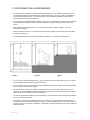
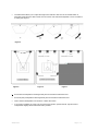
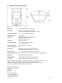
Instruction Manual
SR5 Loudspeaker
Spendor Audio Systems Ltd
SR5IM1.DOC
Page 1 of 9
IMPORTANT
•
PLEASE READ THESE INSTRUCTIONS CAREFULLY BEFORE INSTALLING YOUR NEW
SPENDOR LOUDSPEAKERS
•
DO NOT DRILL ANY HOLES OR FIX ANY SCREWS CLOSE TO ANY AC MAINS OR OTHER
ELECTRICAL CABLES
•
DO NOT DRILL ANY HOLES OR FIX ANY SCREWS CLOSE TO ANY PIPES OR CONDUITS
•
IF YOU ARE UNSURE ABOUT ANY ASPECT OF THE INSTALLATION CONSULT YOUR SPENDOR
DEALER OR A QUALIFIED PROFESSIONAL BEFORE PROCEEDING
•
PLEASE READ THESE INSTRUCTIONS CAREFULLY BEFORE INSTALLING YOUR NEW
SPENDOR LOUDSPEAKERS
•
The Spendor SR5 is designed to perform optimally when it is mounted on a wall.
•
It must be fixed securely to a wall or ceiling using the supplied wall bracket.
•
The wall bracket must be securely fixed using the supplied 3 x screws and 3 x wall plugs. The screws
must be fixed into a solid wall section. This can be brick, block or, if the wall is dry-lined (e.g. wallboard
or plasterboard), a structural timber ‘stud’ or ‘batten’.
•
If the wall is dry-lined and there is no timber batten directly behind the bracket use a suitable expansion
fixing (not supplied). Expansion fixings are available from most hardware stores or builders merchants.
•
If the SR5 is mounted very close to a corner or on a ceiling you can place a solid timber batten (spacer)
between the bracket and the wall to provide a greater range of adjustment. See figure 4. The spacer
can be up to 50mm thick. If a spacer is used, longer fixing screws (not supplied) will be required.
•
For any other installation arrangement seek advice from your Spendor dealer.
•
Install all loudspeaker cables before installing the bracket and allow at least 100mm of free loudspeaker
cable directly behind the loudspeaker terminals.
•
Always position the cabinet as close to the wall as possible while allowing a clear gap of at least 2mm
between the cabinet rear edge and the wall face.
•
Plan the layout of your room and all loudspeaker positions before installing any cables or brackets.
SR5IM1.DOC
Page 2 of 9
1 POSITIONING THE LOUDSPEAKERS
•
The SR5 frequency response is extremely well maintained off-axis. This creates a wide deep precise
sound field which allows great flexibility when planning the layout of your room, seating, loudspeakers,
and associated equipment (e.g. TV or video screen). Use the following guidelines to determine the
optimum positions for your loudspeakers.
•
Try to position the loudspeakers at least 650mm away from any adjacent wall, ceiling or large equipment
cabinet and always install the cabinet so that the distances A, B and C differ by at least 75mm. See
figure 1.
•
As a general guide if the cabinet is 1m or more above floor level mount the cabinet in its normal
orientation. See figure 2.
•
When the cabinet is less than 1m above floor level ‘invert’ the cabinet so the tweeter is above the bassmid driver. See figure 3.
•
The SR5 grille can be fitted to match either cabinet orientation or, if preferred, it can be left off.
Figure 1
Figure 2
Figure 3
•
If your room has a hard reflecting floor, e.g. wood or stone with no sound absorbing rugs, try to position
the loudspeaker cabinets at least 1m above floor level.
•
A rug or carpet on the floor between your front loudspeakers and the main seating area can dramatically
improve the sound of any audio system.
•
If the SR5 is close to a large TV, equipment housing or item of furniture there will be many acoustic
variables. Try the loudspeaker normal and inverted, and choose the orientation which gives the clearest
sound, the best sound image and the smoothest bass.
•
The SR5 is magnetically shielded to prevent interference if it is positioned close to magnetically sensitive
video, TV or computer screens.
•
If you have an acoustically transparent video screen, and you are using the SR5 as a centre channel
loudspeaker, position the cabinet behind the screen as close as possible to the centre of the screen and
remove the grille. If the screen is sufficiently wide the left and right loudspeakers can also be positioned
behind the screen.
SR5IM1.DOC
Page 3 of 9
•
The wall bracket allows you to adjust the angle of the cabinet to fine-tune the sound field which is
especially useful when the SR5 is used as a surround or rear channel loudspeaker or if it is mounted on
a ceiling. See figure 4.
Figure 4
Figure 5
Figure 6
Figure 7
•
Surround/rear loudspeakers should generally be mounted above seated ear level.
•
Surround (side) loudspeakers should generally be mounted above seated ear level.
•
Centre channel loudspeaker can be above or below the screen.
•
If no screen is installed, eg. music only surround sound system, position the left, right and centre
loudspeakers slightly above seated ear level if possible.
SR5IM1.DOC
Page 4 of 9
2 BRACKET AND CABINET INSTALLATION
•
Check that all loudspeaker cables have been prepared and installed. See section 3 Cables and
Connections.
•
The cabinet is secured to the bracket with 2 x M6 hex-drive socket cap machine screws, 2 x spring
washers and 2 x stainless steel bushes. See figure 8. ALWAYS store these components safely
whenever they are removed.
•
Remove the two screws and washers using the supplied 5mm hex wrench and carefully detach the
bracket from the cabinet.
Figure 8
•
Hold the bracket against the wall (or ceiling) in its final location and carefully mark the centres of the
three holes. To ensure a neat installation make sure the bracket is level. See figure 9.
•
Place the bracket to one side.
•
Drill three 5.5mm diameter holes to a clear depth of 30mm. Insert the 3 wall-plugs. Screw the bracket to
the wall using the supplied 3 x No 8 cross-head screws. Before tightening the screws check the
orientation of the bracket.
Figure 9
•
Check that the 2 x bushes are correctly fitted to the cabinet. Carefully locate the cabinet over the bracket
and fit the 2 x M6 screws and 2 x spring washers. Do not tighten the screws completely until all cables
have been connected. Tighten the screws securely but do not use excessive force.
•
To adjust the cabinet angle, loosen the M6 screws slightly, adjust the cabinet, then re-tighten the
screws.
•
Take care not to mark any wall coverings when using the hex wrench.
SR5IM1.DOC
Page 5 of 9
3 CABLES AND CONNECTIONS
•
Loudspeaker cables can have a noticeable effect on sound quality. Choose good quality low resistance
cables with high purity metal conductors and low-loss dielectric (insulation). Ask your dealer for advice
on cables to suit your system and budget.
•
Set amplifier(s) to minimum volume and switch off the power.
•
Always connect the –ve (usually black) loudspeaker output terminal of the amplifier to the corresponding
–ve (Black) terminal on the loudspeaker.
•
Always connect the +ve (usually red) loudspeaker output terminal of the amplifier to the corresponding
+ve (Red) terminal on the loudspeaker.
•
Always connect the left channel amplifier output to the left loudspeaker and the right channel amplifier
output to the right loudspeaker.
•
For surround sound systems the centre, surround and rear loudspeakers must be connected to the
appropriate amplifier outputs.
•
Make the connections as shown below. Only the left channel connection is shown.
•
When all connections have been made. Switch on the amplifier(s). Pick a sound source (e.g. CD or FM)
and advance the volume control carefully.
SINGLE WIRING
Figure 10
BI-WIRING
•
IMPORTANT: REMOVE the terminal links and store them safely.
•
Bi-wiring can improve sound quality by separating the current paths for Low (LF) and High (HF)
frequencies.
Figure 11
SR5IM1.DOC
Page 6 of 9
BI-AMPING
•
IMPORTANT: REMOVE the terminal links and store them safely.
•
Bi-amping allows two independent audio power amplifier of equal or similar quality to be used for LF and
HF signals. The benefits of bi-amping include reduced intermodulation distortion because the low and
high frequency signals are amplified independently, and more power reserve and dynamic range
because each amplifier has less ‘work’ to do than a corresponding single amplifier.
Figure 12
4 POWER RATING
The technical specification shows a nominal power rating for your loudspeaker and the figure can be taken
as a rough guide to the power rating, Watts per channel into 8ohm load, for a complementary amplifier.
However, provided you NEVER play at levels where the sound is strained or distorted, the power rating is not
critical provided you have a minimum of about 15 Watts per channel and a maximum of 250 Watts per
channel available. If the sound is strained always turn the playing level down immediately. Ask your dealer
for advice if you are unsure or if you are choosing a new amplifier.
5 RUNNING-IN
The performance of any loudspeaker will improve subtly during initial use especially if the loudspeaker has
been stored in a cold environment or not used for an extended period. The drive unit suspension and any
damping materials will ‘break in’ and settle during the first 24-48 hours of playing. This running-in period may
vary. Allow up to a week for the loudspeaker temperature to stabilise and a further 48 hours of continual
operation for the loudspeaker to deliver its full potential.
6 MAINTENANCE
Spendor’s real wood veneers and solid timber elements should be treated like high quality furniture. Routine
dusting with a soft cloth is recommended. Do not apply any aerosol spray directly as this could damage the
drive units or grille fabric. Dust on the grille cloth can be removed with a sticky roller or a piece of sticky tape
or by gentle vacuuming with a soft brush adaptor. Do not expose the cabinets to damp, widely fluctuating
temperatures or direct sunlight, the appearance and performance may suffer. The SR5 cabinets are finished
in natural wood, over time the wood will age and mature, often darkening the surface colour while
highlighting the natural grain and patina.
SR5IM1.DOC
Page 7 of 9
7 QUERIES AND SERVICE
If you require advice or service for your audio system please contact your Spendor dealer. We recommend
that you retain all the packaging for your loudspeakers in case you need to transport them safely in the
future.
8 WARRANTY
All Spendor 'S' Series loudspeakers (‘The Equipment’) are guaranteed against defects in components and
materials for a period of 5 years from date of purchase. Within this period parts will be replaced free of
charge provided that failure is not due to accident, negligence or misuse. Labour and carriage are not
covered except by local agreement.
The guarantee offered does not affect the consumer's statutory rights.
To obtain Service under guarantee the equipment together with an original or clear copy of proof of purchase
must be delivered to a local Spendor dealer or distributor at the owner's expense.
Spendor Audio Systems Ltd and any of its authorised distributors or dealers reserve the right to refuse
service under guarantee if the equipment has been subject to unauthorised modification or any of the serial
numbers identifying the equipment have been defaced or removed.
Please register ownership of your Spendor loudspeakers by completing and returning the enclosed
registration card. This will help us to deal quickly with any queries regarding your equipment.
SR5IM1.DOC
Page 8 of 9
9 SPECIFICATIONS [SR5]
Description
2-way sealed enclosure for use on wall
Drive Units
25mm (1in) coated fabric dome tweeter
140mm (5.5in) homopolymer cone bass-mid driver
Frequency response
90Hz - 20kHz ± 3dB on reference axis
Frequency range
-6dB at 70Hz
Dispersion
Within 3dB of response on reference axis
Horizontal: over 40° arc ( ±20°)
Vertical: over 20° arc ( ±10°)
Sensitivity
88dB SPL (1W, 1m)
Harmonic distortion
2nd & 3 rd harmonics (re. 90 dB/1m)
<1% 100Hz – 20kHz
Nominal impedance
8 ohms (minimum 6.0 ohms)
Crossover frequency
5 kHz
Connections
Heavy duty 2/3 way gold plated terminal posts
Independent HF and LF terminals allow bi-wiring
Power handling
15 - 125W into 8 ohms on unclipped programme
Dimensions (W x H x D) 311 x 309 x 176mm (12.2 x 12.1 x 7in) maximum including bracket
Net weight
Net 5.8kg (13lb) including bracket
Cabinet finishes
Cherry, Maple, Rosenut or Black Ash Veneer
Accessories
Stainless steel wall bracket and fixings included
Spendor loudspeakers are magnetically shielded to avoid interaction with video and computer screens
Spendor Loudspeakers are designed and manufactured by Spendor Audio Systems Ltd
Spendor Audio Systems Ltd reserve the right to alter designs and specifications without notice
Spendor is a registered trademark of Spendor Audio Systems Ltd
Spendor Audio Systems Ltd
Station Road Industrial Estate
Hailsham
East Sussex
BN27 2ER
UK
T+44 (0) 1323 843474
F+44 (0) 1323 442254
E [email protected]
www.spendoraudio.com
SR5IM1.DOC
Page 9 of 9