1
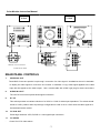
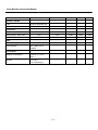
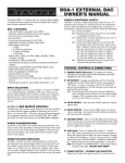
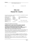
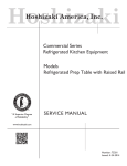
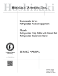
Color Video Monitor
Instruction Manual
Read this manual thoroughly before use,
and retain it for maintenance.
The product’s exterior design and specifications may subject to change
without prior notice for quality improvement.
Color Monitor Instruction Manual
Contents
Page
Warning...............................................................................................3
Precaution ..........................................................................................3
Introduction ........................................................................................3
Important Safeguards ........................................................................4
Accessories........................................................................................5
Features ..............................................................................................5
Function Description for 10 / 14 Inch ...............................................6-7
Function Description for 15 / 17 / 21 Inch ........................................8-9
Operation ............................................................................................10
Installation ..........................................................................................10
Trouble Shooting ...............................................................................10
Specification.......................................................................................11-12
-2-
Color Monitor Instruction Manual
WARNING – To Prevent Fire or Shock Hazard, Do Not
Expose This Monitor To Rain or Moisture.
PRECAUTION
Graphic Symbol Explanation
The lightning flash with arrowhead symbol, within an equilateral triangle, is
Intended to alert the user to the presence of uninsulated ‘dangerous voltage’
within the product’s enclosure that may be of sufficient magnitude to constitute
a risk of electric shock to persons.
The exclamation point within an equilateral triangle is intended to alert the user
to the presence of important operating and maintenance (servicing)
instructions in the literature accompanying the appliance.
SCOPE
The information in this instruction manual covers the installation and operation of the color monitor.
This unit should be installed with approved materials and wiring practices in accordance with the
National Electrical Cord and applicable local wiring ordinances.
INTRODUCTION
The color video monitor features with high resolution both at center & corner, which produces crisp and
high-quality video images for any discreet installation purpose. For industrial applications, the monitor accepts a
standard NTSC or PAL color input signal and loop-through connectors are included with a switchable 75-ohm
termination . Operating controls for tint, color, brightness, contrast and volume are located in the front panel for
easy access. Furthermore, a regulated power supply maintains excellent performance during fluctuation in line
voltage. This monitor is suitable for specialized and industrial CCTV surveillance applications where clear, high
quality pictures and proven system reliability are required.
-3-
Color Monitor Instruction Manual
IMPORTANT SAFEGUARDS
All the safety and operating instructions should be read before the appliance is operated.
1.
Retain instructions: The safety and operating instructions should be retained for future reference.
2.
Heed Warnings: All warnings on the monitor and in the operating instructions should be adhered to.
3.
Follow Instructions: All operating and use instructions should be followed.
4.
Cleaning: Unplug the monitor from the wall outlet before cleaning. Do not use liquid cleaners or aerosol
cleaners. Use a damp cloth for cleaning.
Exception. A monitor that is meant for uninterrupted service and
that for some specific reason, such as the possibility of the loss of an authorization code for a CATV converter,
is not intended to be unplugged by the user for cleaning or any other purpose, may exclude the reference to
unplugging the monitor in the cleaning description otherwise required in item 5.
5.
Attachments: Do not use attachments not recommended by the manufacturer as they may cause hazards.
6.
Water and Moisture: Do not use this monitor near water – for example, a bath tub, wash bowl, kitchen sink, or
laundry tub, in a wet basement, or a swimming pool, and the like.
7.
Accessories: Do not place this monitor on an unstable cart, stand, tripod, bracket, or table. The monitor may
fall, causing serious injury to a child or adult, and serious damage to the appliance. Use only with a cart, stand,
tripod, bracket, or table recommended by the manufacturer, or sold with the monitor.
Any mounting of the
monitor should follow the manufacturer’s instructions, and recommended by manufacturer.
8.
Ventilation: Slots and openings in the cabinet are provided for ventilation and to ensure reliable operation of
the monitor and to protect it from overheating, and these openings should never be blocked by placing her
monitor on a bed, sofa, rug, or other similar surface. This monitor should never be placed near or over a
radiator or heat register. This monitor should not be placed in a built in installation such as a bookcase or rack
unless proper ventilation is provided or the manufacturer instructions have been adhered to.
9.
Power Sources: This monitor should be operated only from the type of power source indicated on the making
label. If you are not sure the type of power supply to the installation site, consult with your dealer or local power
company.
10. Grounding or Polarization: For monitors equipped with a 3-wire grounding type plug having a third (grounding)
pin. This plug will only fit into a grounding-type power outlet. This is a safety feature.
If you are unable to
insert the plug into the outlet, contact your electrician to replace the obsolete outlet. Do not defeat the safety
purpose of the grounding-type plug.
11. Power: Cord Protection-Power supply cords should be routed well so that they are not likely to be walked on or
pinched by items placed upon or against them, paying particular attention to cords at plugs, convenience
receptacles, and the point where they exit from the monitor.
12. Lighting: For added protection for this monitor during a lighting storm, or when it is left unattended and unused
-4-
Color Monitor Instruction Manual
for long periods of time, unplug it from the wall outlet and disconnect the cable system. This will prevent
damage to the monitor due to lighting and power-line surges.
13. Overloading: Do not overload wall outlets and extension cords as this can result in a risk of fire or electric
shock.
14. Object and Liquid Entry: Never push objects of any kind into this monitor through openings as they may touch
dangerous voltage points or short-out parts that could result in a fire or electric shock. Never spill liquid of any
kind on the monitor.
15. Servicing: Do not attempt to service this monitor yourself as opening or removing covers may expose you to
dangerous voltage or other hazards. Refer all servicing to qualified service personnel.
16. Damage Requiring Service: Unplug this monitor from the wall outlet and refer servicing to qualified service
personnel under the following conditions.
a. When the power-supply cord or plug is damaged.
b. If liquid has been spilled, or objects have fallen into the monitor.
c. If the monitor has been exposed to rain or water.
d. If the monitor does not operate normally by following the operating instructions.
Adjust only those controls
that are covered by the operating instructions as an improper adjustment of other controls may result in
damage and will often require extensive work by a qualified technician to restore the monitor to its normal
operation.
e. If the monitor has been dropped or the cabinet has been damaged.
f. When the monitor exhibits a distinct change in performance – this indicates a need for service.
17. Replacement Parts: When replacement parts are required, be sure the service technician has used
replacement parts specified by the manufacturer or have the same characteristics as the original parts.
Unauthorized substitutions may result in fire, electric shock or other hazards.
18. Safety Check: Upon completion of any service or repairs to this monitor, ask the service technician to perform
safety checks to determine that the monitor is in proper operating condition.
ACCESSORIES
FEATURES
This package is basically including:
High resolution ( for 14” , 15” , 17” )
1 x monitor
Looping Video in/out
1 x instruction manual
Y/C in/out ( for 14” , 15” , 17” & 21”)
1 x power cord
Detect and switch NTSC/PAL system automatically
Convenient front controls
Rugged metal cabinet
With optional audio function
-5-
Color Monitor Instruction Manual
FUNCTION DESCRIPTION for 10 / 14 Inch
10 Inch
14 Inch
1
6
1
5
4
3
2
FRONT PANEL CONTROLS
1.
POWER ON/OFF SWITCH
The switch provides power on-off control.
2.
VOLUME (Option)
Rotate the switch for adjustment of the volume when needed.
3.
CONTRAST
The control permits adjustment of the contrast between the light and dark areas of the picture.
4.
BRIGHTNESS
The control supports the adjustment of the overall picture shade and brightness.
5.
COLOR
Permit to adjust the depth or saturation of color in the picture. Used to select individual viewer’s preference in
color saturation.
6.
TINT ( NTSC only )
The control permits adjustment of the R.G.B. phase differences as you need .
-6-
Color Monitor Instruction Manual
10 Inch
AUDIO
IN
14 Inch
VIDEO
IN
S-VHS
VIDEO
LO
Y/C
HI
OUT
OUT
S-VHS
9
AUDIO
IN
8
11
VIDEO
IN
S-VHS
VIDEO
LO
Y/C
OUT
HI
7
9
7
7
S-VHS
OUT
9
8
8
11
OPTION: Y/C FUNCTION
11
10
AUDIO FUNCTION
REAR PANEL CONTROLS
7.
VIDEO IN & OUT
These BNC Connectors permits ‘loop-through’ connection of a video signal in installations where it is desirable
to display the video signal on more than one monitor. A standard 1.0 vp-p video signal applied to the video
input will also appear at the video output . Use a coaxial cable with a BNC type plug for these connections.
8.
AUDIO IN & OUT
The rear RCA connectors permit audio signal connection.
9.
HI / LO
This switch provides convenient selection of a ‘HIGH’ or ‘LOW’ for video input impedance. The switch should
be set to ‘HIGH‘ position when loop-through configuration is used or set to ‘LOW’ when the video signal is to
be terminated at the monitor.
10.
Y/C IN & OUT
Permit high resolution VCD,LD,DVD or V-cam signal input connection.
11.
.
Y/C VIDEO
Control for Y/C & video switch.
-7-
Color Monitor Instruction Manual
FUNCTION DESCRIPTION for 15 / 17 / 21 Inch
When adjusting the controls, LED
light will flash; when adjust to the
end, LED light will stop flash but just
light on. LED light will be totally off
when stop adjusting.
65 43 2
1
FRONT PANEL CONTROLS
1.
POWER ON/OFF SWITCH
The switch provides power on-off control.
2.
TINT ( NTSC only )
The controls permit adjustment of the R.G.B. phase differences as you need .
3.
COLOR
Adjusts the depth or saturation of color in the picture. Used to select individual viewer’s preference in color
saturation.
4.
BRIGHTNESS
The controls support the adjustment of the overall picture shade and brightness.
5.
CONTRAST
The controls permit adjustment of the contrast between the light and dark areas of the picture.
6.
VOLUME (Option)
Push up or down for volume control.
-8-
Color Monitor Instruction Manual
FUNCTION DESCRIPTION for 14 / 15 / 17 / 21 Inch
Grounding
7
C Signal
V1 IN
AU1 IN
V2 IN
AU2 IN
Y/C
IN
9
OUT
V1 OUT
V2 OUT
AU1 OUT
AU2 OUT
8
V1
AU1
V2
AU2
HI
LO
VIDEO
Y/C
Grounding
Y Signal
10
11
12
REAR PANEL CONTROLS
7.
VIDEO IN & OUT
8.
These BNC Connectors permits ‘loop-through’ connection of a video signal in installations where it is desirable
to display the video signal on more than one monitor. A standard 1.0 vp-p video signal applied to the video
input will also appear at the video output . Use a coaxial cable with a BNC type plug for these connections.
AUDIO IN & OUT
9.
The rear RCA connectors permit audio signal connection.
Y/C IN & OUT
10.
Permit high resolution VCD, LD, DVD or V-cam signal input connection.
V1 AUI / V2 AU2
11.
Permit V1 AU1 / V2 AU2 switch at user’s request.
HI / LO
12.
This switch provides convenient selection of a ‘HIGH’ or ‘LOW’ for video input impedance. The switch should
be set to ‘HIGH‘ position when loop-through configuration is used or set to ‘LOW’ when the video signal is to
be terminated at the monitor.
Y/C / VIDEO
Controls for Y/C & video switch.
OPERATING THE MONITOR
1.
2.
3.
4.
5.
6.
Place the monitor where you plan to use it.
This monitor can be operated between 96VAC to 256VAC.
Plug the power cord into AC adapter on the wall.
Link the A/V terminal from your device into the video-in BNC connector of the monitor.
Press POWER switch and the POWER indicator will light. After approximately 10~30 seconds a picture will
appear.
The monitor will detect the frequency of the input signals automatically, and the display image may be able to
be adjusted through the function switch on FRONT CONTROL PANEL.
-9-
Color Monitor Instruction Manual
INSTALLATION
CAUTION: Do not install this monitor in an excessively hot location, or in any way obstruct the ventilation openings
in the cabinet. Premature component failure or damage to the cabinet may result.
When the monitor is not to be used for several days, it is advisable to disconnect the AC power cord from the utility
outlet. To reduce the risk of electric shock , do not remove cover or back. No user-serviceable parts are inside.
Refer servicing to qualified personnel. Some household aerosol sprays, cleaning agents, solvents or polishes may
cause damage to the cabinet finish. Best results for cleaning are obtained with mild soap and water, and a soft
cloth for drying.
INSTALLING THE MONITOR
1.
Connect the coaxial cable from the video equipment to any VIDEO-IN BNC connector of this unit.
2.
If loop-through video configuration is desired, connect a coaxial cable from the VIDEO-OUT BNC connector to
the VIDEO-IN BNC connector on the next monitor. Set HI-LO switch of the first monitor to HIGH and set LOW
for the second or last monitor.
3.
Plug the power cord into the applicable utility outlet.
Note : If the monitor is the last unit in the video loop-through configuration, set its HI-LO switch to low. Each
non-looping video circuit must be terminated either at the unit or at another device such as an additional
switcher. Failure to terminate video circuits with 75 ohm (low) will result in picture degradation, and lack of
color.
TROUBLE SHOOTING
Incorrect operations may result in trouble or malfunction to the unit, before referring to the authorized personnel,
please check the followings firstly and investigate the components and electrical appliances as used. If the troubles
still can not be solved, please ask your dealer for further detailed checking.
Power does not come on even when power switch is pressed
Check if the power cord is connected securely.
Flash Image Display
Adjust the controls (ex. contrast, brightness,….,etc.) well.
Ghosting Image Display
Check if there are any glasses put in front of camera, if not, then contact with your dealer for further examination.
No Image shown on the screen
Check if the video cable and camera are connected well.
-10-
Color Monitor Instruction Manual
SPECIFICATION
General
10”
14” / 14”H
15”H
17”H
21”
Location
Indoor
○
○
○
○
Construction
Steel cabinet with
○
○
○
○
○
○
○
○
20/21
24/25
26 / 27
Plastic front
Finish
Black or white matte
Texture coat finish
N.W. / G.W. (kg)
8.5 / 9.2
Dimension (D x W x H) m/m 262x238x292
Master Carton
(pc/ctn)
2 pcs/ctn
14 / 15
362x318x376
400x362x364 475x420x414 500x490x445
1pc/ctn
1pc/ctn
1pc/ctn
1pc/ctn
○
○
○
Front Panel Controls
Power ON/OFF
Rocker Switch
○
Color / Contrast
Rotary switch
○/Push button
Push button
Push button
Push button
Brightness
Rotary switch
○/Push button
Push button
Push button
Push button
TINT (NTSC only)
Rotary switch
○/Push button
Push button
Push button
Push button
Volume
Rotary switch
○/Push button
Push button
Push button
Push button
Electrical
Input Voltage
96~256 Vac 50Hz/60Hz
Power Consumption
55 W
Input Signal
Composite 1.0 Vp-p
○
○
○
○
40 / 45 W
48 W
50 W
75 W
○
○
○
○
(Video Signal 0.714Vp-p
Sync. Signal: 0.286 Vp-p
Subcarrier Frequency
NTSC
3.58MHz ±200Hz
○
○
○
○
PAL
4.43MHz ±200Hz
○
○
○
○
Input Impedance
75 ohms or high
○
○
○
○
Band Width
6 MHz
6 / 8 MHz
8 MHz
8 MHz
6 MHz
Video Gain
30dB
○
○
○
○
Resolution
Center (TV lines)
350
420 / 600
600
600
520
Corner (TV lines)
330
380 / 500
500
500
330
Linearity
Horizontal
10 % Max
○
○
○
○
Vertical
10 % Max
○
○
○
○
-11-
Color Monitor Instruction Manual
10"
14" /14”H
15"H
17”H
21”
NTSC
525 lines, 60 fields/ sec.
○
○
○
○
PAL
625 lines, 50 fields/ sec.
○
○
○
○
Y/C (In /Out) – 4 pin DIN
“IN” only
“IN” only / IN / OUT
IN / OUT
IN / OUT
IN / OUT
Video (In/Out) – BNC jack
1 set
1 set
2 sets
2 sets
2 sets
With audio – Phone jack
1 set
1 set
2 sets
2 sets
2 sets
10~150mVp-p
○
○
○
○
1W / 8 ohm (Incl. a
○
○
○
○
○
○
○
○
○
○
○
○
Operation System
Connections
Audio
Audio Input Signal
Audio Amplifier
speaker)
Environment
Operation temperature
-10 to 55° C ( 50 to
130°F )
Humidity
0% to 90%
(non-condensing)
-12-