1
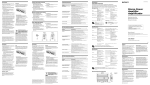
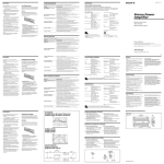
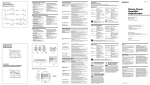
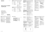
4-300-771-21(1) Specifications Especificaciones AUDIO POWER SPECIFICATIONS POWER OUTPUT AND TOTAL HARMONIC DISTORTION 60 watts per channel minimum continuous average power into 4 ohms, both channels driven from 20 Hz to 20 kHz with no more than 1 % total harmonic distortion per Car Audio Ad Hoc Committee standards. Sistema de circuito Other Specifications Circuit system Stereo Power Amplifier Amplificador OTL (output transformerless) circuit Pulse power supply Inputs RCA pin jacks Input level adjustment range 0.3 – 6 V (RCA pin jacks) Outputs Speaker terminals Speaker impedance 2 – 8 Ω (stereo) 4 – 8 Ω (when used as a bridging amplifier) Maximum output 4 Speakers: 110 W × 4 (at 4 Ω) 3 Speakers: 150 W × 2 (at 2 Ω) + 300 W × 1 (BTL, at 4 Ω) 2 Speakers: 300 W × 2 (BTL, at 4 Ω) Rated output (supply voltage at 14.4 V, 20 Hz – 20 kHz, 1 % THD) 4 Speakers: 60 W × 4 (at 4 Ω) 70 W × 4 (at 2 Ω) Frequency response 5 Hz – 50 kHz ( dB) Harmonic distortion 0.05 % or less (at 1 kHz, 4 Ω) Low-pass filter High-pass filter Power requirements Power supply voltage Current drain Dimensions Mass Supplied accessories 80 Hz, 18 dB/oct 80 Hz, 12 dB/oct 12 V DC car battery (negative ground) 10.5 – 16 V at rated output: 31 A (4 Ω, 60 W × 4) Remote input: 1 mA Approx. 376 × 55 × 252 mm (14 7/8 × 2 1/4 × 10 in) (w/h/d) not incl. projecting parts and controls Approx. 3.0 kg (6 lb 10 oz) not incl. accessories Mounting screws (4) Protection cap (1) Design and specifications are subject to change without notice. CEA2006 Standard Power Output:60 Watts RMS × 4 at 4 Ohms <1 % THD+N SN Ratio:93 dBA (reference: 1 Watt into 4 Ohms) Operating instructions Manual de instrucciones The POWER/PROTECTOR indicator does not light up. The fuse is blown. Replace the fuse with a new one. Problema Causa/Solución El indicador POWER/PROTECTOR no se ilumina. El fusible se ha fundido. Sustitúyalo por otro nuevo. Owner’s Record The model and serial numbers are located on the bottom of the unit. Record the serial number in the space provided below. Refer to these numbers whenever you call upon your Sony dealer regarding this product. Check the battery voltage (10.5 – 16 V). The POWER/PROTECTOR indicator will change from green to red. XM-GTX6041 The unit becomes abnormally hot. The sound is interrupted. Alternator noise is heard. Features (at 4 Ω). This unit can be used as a bridging amplifier with a maximum output of 300 W. Built in Low-pass filter (80 Hz, 18 dB/oct) and High-pass filter (80 Hz, 12 dB/oct). Protection circuit and indicator provided. Pulse power supply* for stable and regulated output power. * Pulse power supply This unit has a built-in power regulator which converts the power supplied by the 12 V DC car battery into high speed pulses using a semiconductor switch. These pulses are stepped up by the built-in pulse transformer and separated into both positive and negative power supplies before being converted into direct current again. This is to regulate fluctuating voltage from the car battery. This light weight power supply system provides a highly efficient power supply with a low impedance output. The power connecting wires are installed too close to the RCA pin cords. Keep the wires away from the cords. Negative speaker wires are touching the car chassis. Keep the wires away from the car chassis. The sound is muffled. The LPF switch is set to the “OFF” position. When connecting the full range speaker, set to “OFF” position. The FILTER select switch is set to the “OFF” position. When connecting the full range speaker, set to “OFF” or “HP” position. The LEVEL adjustment control is not appropriate. Turn the LEVEL adjustment control in the clockwise direction. * Suministro de alimentación por impulsos Esta unidad dispone de un regulador de potencia incorporado que convierte el suministro de alimentación de cc de 12 V de la batería del automóvil en impulsos de alta velocidad mediante un interruptor semiconductor. Estos impulsos se incrementan mediante el transformador de impulsos incorporado y se dividen en suministro de alimentación positiva y negativa antes de volver a convertirse en corriente directa. De esta forma, se regula la tensión fluctuante de la batería del automóvil. Este sistema de suministro de alimentación ligero proporciona una alta eficacia del suministro con una salida de baja impedancia. Dimensions / Dimensiones Unit: mm (in) Unidad: mm 55 (2 1/4) 376 (14 7/8) 252 (10) 234 (9 1/4) 309 (12 1/4 ) Location and Function of Controls POWER/PROTECTOR indicator FILTER select switch Lights up in green during operation. When the switch is in the LP position, the filter is When the PROTECTOR is activated the indicator set to low-pass (80 Hz). When the switch is in the will change from green to red. HP position, the filter is set to high-pass (80 Hz). When the PROTECTOR is activated refer to the LPF switch Troubleshooting Guide. When the LPF switch is set to ON, the Low-pass LEVEL adjustment control filter (80 Hz) is effective. The input level can be adjusted with this control. Turn it in the clockwise direction when the output level of the car audio unit seems low. Ubicación y función de los controles Indicador POWER/PROTECTOR Interruptor de selección del FILTER Se ilumina en verde durante el uso. Cuando el interruptor se encuentra en la posición Si se activa PROTECTOR, el indicador cambiará de LP, el filtro está ajustado en paso bajo (80 Hz). verde a rojo. Cuando el interruptor se encuentra en la posición Si se activa PROTECTOR, consulte la Guía de HP, el filtro está ajustado en paso alto (80 Hz). solución de problemas. Interruptor LPF Control de ajuste LEVEL Cuando el interruptor LPF está ajustado en ON, se Mediante este control se puede ajustar el nivel de activa el filtro de paso bajo (80 Hz). entrada. Gírelo en el sentido de las agujas del reloj si el nivel de salida del sistema de audio para automóvil parece bajo. Apague el interruptor de alimentación. Se ha producido un cortocircuito en las salidas de altavoz. Rectifique la causa del cortocircuito. This unit is designed for negative ground 12 V DC operation only. Use speakers with an impedance of 2 to 8 Ω (4 to 8 Ω when used as a bridging amplifier). Do not connect any active speakers (with built-in amplifiers) to the speaker terminals of the unit. Doing so may damage the active speakers. Avoid installing the unit in areas subject to: — high temperatures such as from direct sunlight or hot air from the heater — rain or moisture — dust or dirt. If your car is parked in direct sunlight and there is a considerable rise in temperature inside the car, allow the unit to cool down before use. When installing the unit horizontally, be sure not to cover the fins with the floor carpet etc. If this unit is placed too close to the car audio unit or antenna, interference may occur. In this case, relocate the amplifier away from the car audio unit or antenna. If no power is being supplied to the car audio unit, check the connections. This power amplifier employs a protection circuit* to protect the transistors and speakers if the amplifier malfunctions. Do not attempt to test the protection circuits by covering the heat sink or connecting improper loads. Do not use the unit on a weak battery as its optimum performance depends on a good power supply. For safety reasons, keep your car audio unit volume moderate so that you can still hear sounds outside your car. Warning When replacing the fuse, be sure to use one matching the amperage stated above the fuse holder. Never use a fuse with an amperage rating exceeding the one supplied with the unit as this could damage the unit. * Protection circuit This amplifier is provided with a protection circuit that operates in the following cases: — when the unit is overheated — when a DC current is generated — when the speaker terminals are short-circuited. The color of the POWER/PROTECTOR indicator will change from green to red, and the unit will shut down. If this happens, turn off the connected equipment, take out the cassette tape or disc, and determine the cause of the malfunction. If the amplifier has overheated, wait until the unit cools down before use. If you have any questions or problems concerning your unit that are not covered in this manual, please consult your nearest Sony dealer. Fuse Replacement If the fuse blows, check the power connection and replace both the fuses. If the fuse blows again after replacement, there may be an internal malfunction. In such a case, consult your nearest Sony dealer. Apague el interruptor de alimentación. Asegúrese de que el cable del altavoz y el de toma a tierra estén conectados firmemente. La unidad se calienta de forma exagerada. El sonido se interrumpe. Se escucha ruido del alternador. La unidad se calienta de forma exagerada. Utilice altavoces con una impedancia adecuada. de 2 a 8 Ω (estéreo) , 4 a 8 Ω (cuando se utiliza como amplificador en puente). Coloque la unidad en un lugar bien ventilado. Se ha activado el protector térmico. Reduzca el volumen. Los cables de conexión de alimentación se encuentran demasiado cerca de los cables con terminales RCA. Manténgalos alejados entre sí. El cable de toma a tierra no está firmemente conectado. Conéctelo firmemente a un punto metálico del automóvil. The unit heats up abnormally. Use speakers with suitable impedance. 2 – 8 Ω (stereo), 4 – 8 Ω (when used as a bridging amplifier). Make sure to place the unit in a well ventilated location. The thermal protector is activated. Reduce the volume. Características puente con una salida máxima de 300 W. Filtro de paso bajo (80 Hz, 18 dB/oct) y filtro de paso alto (80 Hz, 12 dB/oct) incorporados. Se proporciona un circuito de protección y un indicador. Suministro de alimentación por impulsos* para obtener una potencia de salida estable y regulada. El indicador POWER/PROTECTOR cambia de verde a rojo. Los cables negativos del altavoz han entrado en contacto con el chasis del automóvil. Manténgalos alejados del chasis. El sonido se amortigua. The ground wire is not securely connected. Fasten the ground wire securely to a metal point of the car. The sound is too low. Salida máxima de 110 W por canal (a 4 Ω). Esta unidad puede utilizarse como amplificador en Compruebe la tensión de la batería (de 10,5 a 16 V). Turn off the power switch. Make sure the speaker cord and ground wire are securely connected. Model No. XM-GTX6041 Serial No. Maximum power output of 110 W per channel Turn off the power switch. The speaker outputs are shorted. Rectify the cause of the short. El cable de toma a tierra no está firmemente conectado. Conéctelo firmemente a un punto metálico del automóvil. La tensión que recibe el terminal remoto es demasiado baja. No ha activado el sistema de audio para automóvil conectado. Actívelo. El sistema emplea demasiados amplificadores. Utilice un relé. The ground wire is not securely connected. Fasten the ground wire securely to a metal point of the car. The voltage going into the remote terminal is too low. The connected car audio unit is not turned on. Turn on the car audio unit. The system employs too many amplifiers. Use a relay. Diseño y especificaciones sujetos a cambios sin previo aviso. La siguiente lista le resultará útil para solucionar la mayoría de los problemas que pueda encontrar con la unidad. Antes de consultar la lista, examine los procedimientos de conexión y funcionamiento. The following checklist will assist in the correction of most problems which you may encounter with your unit. Before going through the checklist below, refer to the connection and operating procedures. Cause/Solution Filtro de paso bajo 80 Hz, 18 dB/oct Filtro de paso alto 80 Hz, 12 dB/oct Requisitos de alimentación Batería de automóvil de cc de 12 V (negativo a masa) Tensión de suministro de alimentación de 10,5 a 16 V Consumo de energía Con salida nominal: 31 A (4 Ω, 60 W × 4) Entrada remota: 1 mA Dimensiones Aprox. 376 × 55 × 252 mm (an/al/prf), componentes y controles salientes excluidos Masa Aprox. 3,0 kg, accesorios excluidos Accesorios suministrados Tornillos de montaje (4) Cubierta protectora (1) Guía de solución de problemas Troubleshooting Guide Problem Precautions Circuito OTL (salida sin transformador) Suministro de alimentación por impulsos Entradas Tomas con terminales RCA Margen de ajuste de nivel de entrada de 0,3 a 6 V (tomas con terminales RCA) Salidas Terminales de altavoz Impedancia de altavoz de 2 a 8 Ω (estéreo) de 4 a 8 Ω (cuando se utiliza como amplificador en puente) Salida máxima 4 altavoces: 110 W × 4 (a 4 Ω) 3 altavoces: 150 W × 2 (a 2 Ω) + 300 W × 1 (BTL, a 4 Ω) 2 altavoces: 300 W × 2 (BTL, a 4 Ω) Salida nominal (tensión de suministro a 14,4 V, de 20 Hz a 20 kHz, 1 % THD) 4 altavoces: 60 W × 4 (a 4 Ω) 70 W × 4 (a 2 Ω) Respuesta de frecuencia de 5 Hz a 50 kHz ( dB) Distorsión armónica 0,05 % o inferior (a 1 kHz, 4 Ω) El sonido es demasiado bajo. El interruptor LPF está ajustado en la posición “OFF”. Al conectar el altavoz de gama completa, ajuste el selector en la posición “OFF”. Precauciones El interruptor de selección del FILTER está ajustado en la posición “OFF”. Al conectar el altavoz de gama completa, ajuste el selector en la posición “OFF” o “HP”. de 12 V negativo a masa. Emplee altavoces con impedancia de 2 a 8 Ω (de 4 a 8 Ω cuando se utilice como amplificador en puente). No conecte altavoces activos (con amplificadores incorporados) a los terminales de altavoz de la unidad, ya que puede dañar dichos altavoces. Evite instalar la unidad en lugares expuestos a: — altas temperaturas, como a la luz solar directa o al aire caliente de la calefacción — la lluvia o la humedad — suciedad o polvo. Si aparca el automóvil bajo la luz solar directa y se produce un considerable aumento de temperatura en el interior, deje que la unidad se enfríe antes de utilizarla. Si instala la unidad horizontalmente, asegúrese de no cubrir las aletas con la moqueta del suelo, etc. Si coloca la unidad demasiado cerca del sistema de audio para automóvil o de la antena, pueden producirse interferencias. En este caso, instale el amplificador alejado de dichos dispositivos. Si el sistema de audio para automóvil no recibe alimentación, compruebe las conexiones. Este amplificador de potencia emplea un circuito de protección* para proteger los transistores y los altavoces en caso de que dicho amplificador presente fallas de funcionamiento. No intente someter a prueba los circuitos de protección cubriendo el disipador de calor o conectando cargas inadecuadas. No utilice la unidad si la batería se está agotando, ya que el rendimiento óptimo de dicha unidad depende de un buen suministro de alimentación. Por razones de seguridad, mantenga el volumen del sistema de audio para automóvil en un nivel moderado de forma que sea posible oír los sonidos del exterior del automóvil. El control de ajuste LEVEL no es apropiado. Gire el control de ajuste LEVEL en el sentido de las agujas del reloj. Esta unidad está diseñada para utilizarse sólo con cc Sustitución del fusible Si el fusible se funde, compruebe la conexión de alimentación y sustituya ambos fusibles. Si el fusible se funde de nuevo después de sustituirlo, es posible que exista una falla de funcionamiento interno. En este caso, póngase en contacto con el distribuidor Sony más próximo. Advertencia Al sustituir el fusible, asegúrese de utilizar uno cuyo amperaje coincida con el especificado en el portafusible. No utilice nunca un fusible con un amperaje superior al del suministrado con la unidad, ya que podría dañar la unidad. * Circuito de protección Este amplificador dispone de un circuito de protección que se activa en los siguientes casos: — si la unidad se calienta excesivamente — si se genera corriente cc —si se produce un cortocircuito en los terminales de altavoz. El color del indicador POWER/PROTECTOR cambiará de verde a rojo y la unidad se desactivará. Si esto ocurre, desactive el equipo conectado, extraiga la cinta de casete o el disco y determine la causa de la falla de funcionamiento. Si el amplificador se ha sobrecalentado, espere hasta que la unidad se enfríe antes de volver a utilizarla. Si desea realizar alguna consulta o solucionar algún problema relativos a la unidad que no aparezcan en este manual, póngase en contacto con el distribuidor Sony más próximo. Connections / Conexiones Parts for Installation and Connections / Componentes de instalación y conexiones Turn on or off the LPF and HPF switch at the unit rear as illustrated below. Conexiones de los altavoces to a metal point of the car a un punto metálico del automóvil Speaker Connections Power Connection Wires (not supplied) Cables de conexión de alimentación (no suministrados) Encienda o apague los interruptores LPF y HPF situados en la parte posterior de la unidad, como se muestra a continuación. ø 5 × 15 mm (× 4) Remote output*1 Salida remota*1 4-Speaker System Sistema de 4 altavoces 2-Way System Sistema de 2 vías Left Izquierdo less than 450 mm (18 in) menos de 450 mm Full range speakers (min. 2 Ω) Altavoces de gama completa (mín. 2 Ω) Right Derecho Installation Before Installation Mount the unit either inside the trunk or under a seat. Choose the mounting location carefully so the unit will not interfere with the normal movements of the driver and it will not be exposed to direct sunlight or hot air from the heater. Do not install the unit under the floor carpet, where the heat dissipation from the unit will be considerably impaired. First, place the unit where you plan to install it, and mark the positions of the 4 screw holes on the mounting board (not supplied). Then drill a 3 mm (1/8 in) pilot hole at each mark and mount the unit onto the board with the supplied mounting screws. The mounting screws are all 15 mm (19/32 in) long, so make sure that the mounting board is thicker than 15 mm (19/32 in). *2 Car audio unit Sistema de audio para automóvil Fuse (50 A) Fusible (50 A) Left Izquierdo Front speaker (min. 2 Ω) Altavoces delanteros (mín. 2 Ω) Right Derecho +12V car battery Batería de automóvil de +12V *1If you have the factory original or some other car audio unit without a remote output for the amplifier, connect the remote input terminal (REMOTE) to the accessory power supply. *1Si dispone del sistema de audio para automóvil original de fábrica o de otro sistema sin una salida remota para el amplificador, conecte el terminal de entrada remota (REMOTE) a la fuente de alimentación auxiliar. Left Izquierdo Right Derecho Instalación Antes de realizar la instalación Monte la unidad en el interior del maletero o debajo de un asiento. Elija cuidadosamente el lugar de instalación de forma que la unidad no dificulte las maniobras normales del conductor y no quede expuesta a la luz solar directa ni al aire caliente de la calefacción. No instale la unidad debajo de la moqueta del suelo, en cuyo caso la disipación de calor de la misma disminuirá considerablemente. Mount the unit as illustrated. Monte la unidad tal como se muestra en la ilustración. En primer lugar, coloque la unidad donde tenga previsto instalarla y marque sobre la superficie del tablero de montaje (no suministrado) las posiciones de los 4 orificios para los tornillos. A continuación, perfore los orificios con un diámetro de aproximadamente 3 mm y monte la unidad sobre el tablero con los tornillos de montaje suministrados. Ya que la longitud de estos tornillos es de 15 mm, compruebe que el grosor del tablero de montaje sea superior a 15 mm. Notes on the power supply Notas sobre la fuente de alimentación Subwoofer (min. 2 Ω) Altavoz potenciador de graves (mín. 2 Ω) All power wires connected to the positive battery post should be fused within 450 mm (18 in) of the battery post, and before they pass through any metal. Make sure that the vehicle’s battery wires connected to the vehicle (ground to chassis)*2 are of a wire gauge at least equal to that of the main power wire connected from the battery to the amplifier. During full-power operation, a current of more than 50 A will run through the system. Therefore, make sure that the wires to be connected to the +12V and GND terminals of this unit are at least 10-Gauge (AWG-10) or have a sectional area of more than 5 mm2 (7/32 in2). Connect the +12V power supply wire only after all the other wires have been connected. Be sure to connect the ground wire of the unit securely to a metal point of the car. A loose connection may cause a malfunction of the amplifier. Be sure to connect the remote control wire of the car audio unit to the remote terminal. When using a car audio unit without a remote output on the amplifier, connect the remote input terminal (REMOTE) to the accessory power supply. Use a power supply wire with a fuse attached (50 A). Left Izquierdo Note In this system, the volume of the subwoofer will be controlled by the car audio unit fader control. Right Derecho Nota En este sistema, el volumen del altavoz potenciador de graves se controla mediante el control de equilibrio entre altavoces del sistema de audio para automóvil. Rear speaker (min. 2 Ω) Altavoces traseros (mín. 2 Ω) Todos los cables de alimentación conectados al polo positivo de la batería deben conectarse a un fusible situado a menos de 450 mm del polo de la batería, y antes de pasar por ninguna pieza metálica. Asegúrese de que los cables de la batería del vehículo conectados al mismo (a la masa del chasis)*2 Tengan una anchura igual o superior a la del cable de alimentación principal que conecta la batería con el amplificador. Durante el funcionamiento a pleno rendimiento, fluye por el sistema una corriente superior a 50 A. Por tanto, compruebe que los cables que va a conectar a los terminales de +12V y GND de esta unidad son del calibre 10 (AWG 10) como mínimo o presentan un área de sección superior a 5 mm2. Conecte el cable de la fuente de alimentación de +12V sólo después de haber conectado los otros cables. Asegúrese de conectar firmemente el cable de toma a tierra de la unidad a un punto metálico del automóvil. Una conexión floja puede causar fallas de funcionamiento del amplificador. Compruebe que conecta el cable de control remoto del sistema de audio para automóvil al terminal remoto. Si utiliza un sistema de audio para automóvil sin salida remota en el amplificador, conecte el terminal de entrada remota (REMOTE) a la fuente de alimentación auxiliar. Emplee el cable de la fuente de alimentación con un fusible fijado (50 A). 2-Speaker System Sistema de 2 altavoces Left Izquierdo Right Derecho Subwoofer (min. 4 Ω) Altavoz potenciador de graves (mín. 4 Ω) Input Connections / Conexiones de entrada Cautions Before making any connections, disconnect the ground terminal of the car battery to avoid short circuits. Be sure to use speakers with an adequate power rating. If you use small capacity speakers, they may be damaged. This is a Phase-Inverted Amplifier. Do not connect the terminal of the speaker system to the car chassis, and do not connect the terminal of the right speaker with that of the left speaker. Install the input and output cords away from the power supply wire as running them close together can generate some interference noise. Precaución Antes de realizar las conexiones, desconecte el terminal de toma a tierra de la batería del automóvil para evitar cortocircuitos. Asegúrese de utilizar altavoces con una potencia nominal adecuada. Si emplea altavoces de capacidad reducida, pueden dañarse. Este amplificador es de fase invertida. No conecte el terminal del sistema de altavoces al chasis del automóvil, ni el terminal del altavoz derecho al del altavoz izquierdo. Instale los cables de entrada y salida alejados del cable de la fuente de alimentación, ya que en caso contrario puede generarse ruido por interferencias. This unit is a high powered amplifier. Therefore, it may not perform to its full potential if used with the speaker cords supplied with the car. If your car is equipped with a computer system for navigation or some other purpose, do not remove the ground wire from the car battery. If you disconnect the wire, the computer memory may be erased. To avoid short circuits when making connections, disconnect the +12V power supply wire until all the other wires have been connected. Line Input Connection Conexión de entrada de línea Car audio unit Sistema de audio para automóvil Left Izquierdo Right Derecho )9 <,16 $" 53@ "65@ 3-+;9651+: 5+ B"65@C >)99)5;: ;01: 796,<+; )/)15:; ,-.-+;: 15 4);-91)3 69 >6924)5:017 .69 ;0- ;147-916,: )5, ): :-; .69;0 *-36> >0-5 7<9+0):-, ,19-+;3@ .964 "65@ 69 ) "65@ !-;)13-9 <9:<)5; ;6 ;01: 141;-, &)99)5;@ "65@ >133 ); 1;: 67;165 1 9-7)19 ;0- 796,<+; <:15/ 5-> 69 9-.<9*1:0-, 7)9;: 69 11 9-73)+- ;0- 796,<+; >1;0 ) 5-> 69 9-.<9*1:0-, 796,<+; 69 7<976:-: 6. ;01: 141;-, &)99)5;@ B9-.<9*1:0-,C 4-)5: ) 796,<+; 69 7)9; ;0); 0): *--5 9-;<95-, ;6 1;: 691/15)3 :7-+1.1+);165: In the event of a defect, these are your exclusive remedies. Labor: 69 ) 7-916, 6. 65- @-)9 .964 ;0- 691/15)3 ,);- 6. 7<9+0):- 6. ;0- 796,<+; B)*69 &)99)5;@C "65@ >133 ); 1;: 67;165 9-7)19 69 9-73)+- >1;0 5-> 69 9-.<9*1:0-, 796,<+; 796,<+; ,-;-9415-, ;6 *- ,-.-+;1=- . "65@ -3-+;: ;6 9-73)+- ;0- 796,<+; ).;-9 ;01: )*69 &)99)5;@ 0): -?719-, *<; >013- ;0- )9;: &)99)5;@ *-36> 1: :;133 15 -..-+; 1; >133 ,6 :6 .69 ;0- )7731+)*3- 3)*69 +0)9/- Rear Traseros tanto, puede no funcionar a pleno rendimiento si se utiliza con los cables de altavoz suministrados con el automóvil. Si el automóvil está equipado con un sistema de ordenador para la navegación o para otra finalidad, no desconecte el conductor de toma a tierra de la batería del automóvil. Si lo desconecta, la memoria del ordenador puede borrarse. Para evitar cortocircuitos al realizar las conexiones, desconecte el cable de la fuente de alimentación de +12V hasta conectar todos los cables. Full range speakers (min. 2 Ω) Altavoces de gama completa (mín. 2 Ω) LINE OUT Front Delanteros Esta unidad es un amplificador de alta potencia. Por 3-Speaker System Sistema de 3 altavoces LIMITED WARRANTY LINE OUT Make the terminal connections as illustrated below. Realice las conexiones de terminal como se ilustra a continuación. Subwoofer (min. 4 Ω) Altavoz potenciador de graves (mín. 4 Ω) Parts: 69 ) 7-916, 6. 65- @-)9 .964 ;0- 691/15)3 ,);- 6. 7<9+0):- 6. 796,<+; B)9;: &)99)5;@C "65@ >133 :<773@ 5-> 69 9-.<9*1:0-, 9-73)+-4-5; 7)9;: 15 -?+0)5/- .69 7)9;: ,-;-9415-, ;6 *- ,-.-+;1=- #01: 141;-, &)99)5;@ +6=-9: 653@ ;0- 0)9,>)9- +64765-5;: 7)+2)/-, >1;0 ;0- 96,<+; ; ,6-: 56; +6=-9 ;-+051+)3 )::1:;)5+- .69 0)9,>)9- 69 :6.;>)9- <:)/- )5, 1; ,6-: 56; +6=-9 )5@ :6.;>)9- 796,<+;: >0-;0-9 69 56; +65;)15-, 15 ;0- 96,<+; )5@ :<+0 :6.;>)9- 1: 796=1,-, B" "C <53-:: -?79-::3@ 796=1,-, .69 15 )5@ -5+36:-, :6.;>)9- 141;-, &)99)5;@ 3-):- 9-.-9 ;6 ;0- 5, $:-9 1+-5:- /9--4-5;: 15+3<,-, >1;0 ;0- 96,<+; .69 @6<9 91/0;: )5, 6*31/);165: >1;0 9-:7-+; ;6 ;0- :6.;>)9- Instructions: #6 6*;)15 >)99)5;@ :-9=1+- @6< 4<:; ,-31=-9 ;0- 796,<+; .9-1/0; 79-7)1, 15 -1;0-9 1;: 691/15)3 7)+2)/15/ 69 7)+2)/15/ )..69,15/ )5 -8<)3 ,-/9-- 6. 796;-+;165 ;6 ;0- "65@ )<;0691A-, :-9=1+- .)+131;@ :7-+1.1-, It is your responsibility to backup any data, software or other materials you may have stored or preserved on your unit. It is likely that such data, software, or other materials will be lost or reformatted during service and Sony will not be responsible for any such damage or loss. ,);-, 7<9+0):- 9-+-17; .964 "65@ 69 ) "65@ !-;)13-9 1: 9-8<19-, 69 :7-+1.1+ 15:;9<+;165: 65 06> ;6 6*;)15 >)99)5;@ :-9=1+- .69 @6<9 796,<+; Subwoofer (min. 4 Ω) Altavoz potenciador de graves (mín. 4 Ω) %1:1; "65@D: &-* "1;- www.sony.com/support Line Input Connection Conexión de entrada de línea Car audio unit Sistema de audio para automóvil LINE OUT Left Izquierdo Right Derecho Notes In this system, the volume of the subwoofer will be controlled by the car audio unit fader control. In this system, the output signals to the subwoofer will be the combination of both the REAR L and R INPUT jacks’ signals. Notas En este sistema, el volumen del altavoz potenciador de graves se controla mediante el control de equilibrio entre altavoces del sistema de audio para automóvil. En este sistema, las señales de salida que recibe el altavoz potenciador de graves serán la combinación las señales de las tomas REAR L y R INPUT. 9 +)33 ;0- Sony Customer Information Service Center 1-800-222-SONY(7669) 69 )5 )++-::69@ 69 7)9; 56; )=)13)*3- .964 @6<9 )<;0691A-, ,-)3-9 +)33 "( Repair / Replacement Warranty: #01: 141;-, &)99)5;@ :0)33 )773@ ;6 )5@ 9-7)19 9-73)+-4-5; 7)9; 69 9-73)+- 4-5; 796,<+; .69 ;0- 9-4)15,-9 6. ;0- 691/15)3 141;-, &)99)5;@ 7-916, 69 .69 515-;@ ,)@: >01+0-=-9 1: 365/-9 5@ 7)9;: 69 796,<+; 9-73)+-, <5,-9 ;01: 141;-, &)99)5;@ >133 *-+64- ;0- 7967-9;@ 6. "65@ #01: 141;-, &)99)5;@ 653@ +6=-9: 796,<+; 1::<-: +)<:-, *@ ,-.-+;: 15 4);-91)3 69 >6924)5:017 ,<915/ 69,15)9@ +65:<4-9 <:- 1; ,6-: 56; +6=-9 796,<+; 1::<-: +)<:-, *@ )5@ 6;0-9 9-):65 15+3<,15/ *<; 56; 3141;-, ;6 796,<+; 1::<-: ,<- ;6 +644-9+1)3 <:- )+;: 6. 6, 41:<:- 3141;);165: 6. ;-+05636/@ 69 46,1.1+);165 6. 69 ;6 )5@ 7)9; 6. ;0- "65@ 796,<+; 69 796,<+; 7<9+0):-, .964 6;0-9 ;0)5 "65@ 69 ) "65@ !-;)13-9 #6 ,-;-9415- 1. ) 9-;)13-9 1: 7)9; 6. ;0- "65@ !-;)13-9 -;>692 73-):- +65;)+; "65@D: <:;64-9 "-9=1+- )33 -5;-9 69 /6 ;6 >>>:65@+64 :<7769; #01: 141;-, &)99)5;@ ,6-: 56; +6=-9 "65@ 796,<+;: :63, " " 69 &# $#" 69 +65:<4)*3-: :<+0 ): .<:-: 69 *);;-91-: #01: 141;-, &)99)5;@ 1: 15=)31, 1. ;0- .)+;69@)7731-, :-91)3 5<4*-9 0): *--5 )3;-9-, 69 9-46=-, .964 ;0- 796,<+; #01: 141;-, &)99)5;@ 1: =)31, 653@ 15 ;0- $51;-, ";);-: LIMITATION ON DAMAGES: "( " # ! ( # ! " $# " ! ! ( '!"" ! &!!#( #" !$# Pass the wires through the cap, connect the wires, then cover the terminals with the cap. When you tighten the screw, be careful not to apply too much torque* as doing so may damage the screw. DURATION OF IMPLIED WARRANTIES: '# # # '## !# ( & ( &!!#( !##( ! #"" ! !#$! $!" #" !$# " # $!# # # $!# #" &!!#( Pase los cables a través de la cubierta, conéctelos y cubra los terminales con dicha cubierta. "64- :;);-: ,6 56; )336> ;0- -?+3<:165 69 3141;);165 6. 15+1,-5;)3 69 +65:-8<-5;1)3 ,)4)/-: 69 )336> 3141;);165: 65 06> 365/ )5 14731-, >)99)5;@ 3):;: :6 ;0- )*6=- 3141;);165: 69 -?+3<:165: 4)@ 56; )773@ ;6 @6< #01: 141;-, &)99)5;@ /1=-: @6< :7-+1.1+ 3-/)3 91/0;: )5, @6< 4)@ 0)=- 6;0-9 91/0;: >01+0 =)9@ .964 :;);- ;6 :;);- Note * The torque value should be less than 1 N•m. Nota Al apretar el tornillo, tenga cuidado de no aplicar demasiada fuerza de torsión*, ya que puede dañarlo. * El valor de fuerza de torsión debe ser inferior a 1 N•m.