1
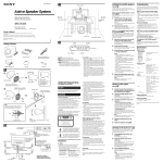
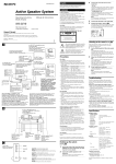
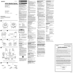
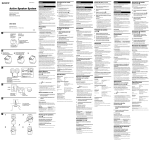
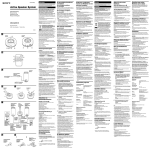
3-264-412-11(1) C PC, CD or MD Walkman, etc. Installing the satellite speakers Troubleshooting (See fig. A) Should you encounter a problem with your speaker system, check the following list and take the indicated measures. If the problem persists, consult your nearest Sony dealer. Use the supplied screws to attach the base to the satellite speaker. The satellite speaker can be used either placed on a desk or attached to a wall. Active Speaker System When you use the satellite speaker on a desk (See fig. A-A) By attaching the base to the satellite speaker, it can be placed on a desk. Operating Instructions Manual de instrucciones 1 Attach the base with the anchor holes facing forward. The base allows you to adjust the satellite speaker to the desired angle. SRS-D2100 2 2004 Sony Corporation Owner’s Record When you use the satellite speaker attached to a wall (See fig. A-B) Front speaker (Right) Model No. SRS-D2100 Serial No. By attaching the base to the satellite speaker, it can be attached to a wall. Follow the Notes (below) to install safely. Improper installation may result in the speaker falling and causing bodily injury or damage to the speaker or other object. 1 D Package Contents POWER PHONES 2 POWER MIN PHONE MAX VOLUME Control box BASS VOLUME Satellite speaker (2) Connecting Cable (1) Base (2) Screw (2) A On operation Before operating the unit, please read this manual thoroughly and retain it for future reference. A Base WARNING Screw , Satellite speaker The speaker angle can be changed by attaching the base back to front. Attach the base with the anchor holes facing forward Do not install the appliance in a confined space, such as a bookcase or built-in cabinet. Attach the base with the anchor holes uppermost B To prevent fire or shock hazard, do not expose the unit to rain or moisture. To avoid electrical shock, do not open the cabinet. Refer servicing to qualified personnel only. To prevent fire, do not cover the ventilation of the apparatus with news papers, table-cloths, curtains, etc. Do not place lighted candles on the apparatus. To prevent fire or shock hazard, do not place objects filled with liquids, such as vases, on the apparatus. Anchor holes Hollow wall anchors (ø 4 mm, not supplied) CAUTION You are cautioned that any changes or modification not expressly approved in this manual could void your authority to operate this equipment. NOTICE FOR THE CUSTOMERS IN THE USA , Satellite speaker Screw Base , First, be sure to apply a bond (anaerobic threadlocking material) to the hollow wall anchor to prevent the screw loosening. This symbol is intended to alert the user to the presence of uninsulated “dangerous voltage” within the product’s enclosure that may be of sufficient magnitude to constitute a risk of electric shock to persons. 5 mm 7 mm This symbol is intended to alert the user to the presence of important operating and maintenance (servicing) instructions in the literature accompanying the appliance. ø 4 mm Note Do not hang on the satellite speaker or hang anything on it. 9.5 mm or more If the TV picture or monitor display is magnetically distorted Although this system is magnetically shielded, there may be cases that the picture on some TV sets/personal computers may become magnetically distorted. In such a case, turn off the power of the TV set/personal computer once, and after 15 to 30 minutes turn it on again. In the case of a personal computer, take appropriate measures, such as data storage, before turning it off. When there seems to be no improvement, locate the system farther away from the TV set/personal computer. Furthermore, be sure not to place objects in which magnets are attached or used near the TV set/ personal computer, such as audio racks, TV stands, toys etc. These may cause magnetic distortion to the picture due to their interaction with the system. 4 Precautions The nameplate indicating operating voltage, power consumption, etc., is located on the rear exterior. • Before operating the system, be sure that the operating voltage of the system is identical with that of your local power supply. Connecting cord (not supplied) to INPUT2 jack to LINE OUT or headphones jack (stereo mini-jack) CD/MD Walkman*, etc Control Box (rear) to INPUT1 jack to 8-pin Din jack Connecting Cable (supplied) to LINE OUT or headphones jack Satellite speaker (rear) to Front R jack PC, etc. Subwoofer (rear) to Front L jack * “WALKMAN” is a registered trademark of Sony Corporation to represent Headphone Stereo products. to wall outlet Where purchased Operating voltage U.S.A./Canada 120 V AC, 60 Hz European countries 220 – 230 V AC, 50 Hz Other countries • 110 – 120 V AC, 50/60 Hz • 220 – 230 V AC, 50 Hz • The unit is not disconnected from the AC power source (mains) as long as it is connected to the wall outlet, even if the unit itself has been turned off. • Unplug the system from the wall outlet if it is not to be used for an extended period of time. To disconnect the cord, pull the cord by grasping the plug. Never pull the cord itself. • Should any liquid or solid object fall into the system, unplug the system’s power cord and have the system checked by qualified personnel before operating it any further. • The AC power cord should be changed only at a qualified service shop. • For efficient heat dissipation, ensure there is sufficient space to the rear of the subwoofer. Also, avoid placing objects on the unit. • Do not insert your hand or any objects into the hole of the subwoofer. • Turn down the volume level on the connected component. Or, if the connected component has a BASS BOOST function, set it to off. • Rotate BASS on this unit to reduce the bass volume. • Turn VOLUME on this unit down to reduce the volume. The sound has suddenly stopped. Make sure all the connections have been correctly made. The brightness of the POWER indicator is unstable. The brightness of the POWER indicator may become unstable when the volume is turned up. This is not a malfunction. Specifications Speaker section Satellite speaker Speaker system Speaker units Enclosure type Impedance Cord length Speaker system Speaker units Enclosure type Impedance Amplifier section Rated output Input Input impedance Output General Dimensions (w/h/d) Ensure that the satellite speaker is securely attached to the wall before use. Hooking up the system Mass (See fig. B) 1 2 Do not use alcohol, benzene, or thinner to clean the cabinet. Optional accessories Connect the control box to the source equipment. To switch INPUT1 and INPUT2, use ON/OFF of the device connected to the control box. 4 Connect the subwoofer to the wall outlet. 5 Position the speakers. (See fig. C) Listening to the sound (See fig. D) First, turn down the volume on the control box. The volume should be set to minimum before you begin playing the programme source. Set the POWER switch to ON on the control box. The POWER indicator lights up. 2 Adjust the VOLUME control on the control box. You can adjust the volume of the subwoofer and each satellite speaker. When connecting to the headphone output, also adjust the volume of the connected component. After listening, set the POWER switch to OFF. The POWER indicator goes off. 3 Approx. 130 × 40 × 73 mm (5 1/8 × 1 5/8 × 2 7/8 in.) (Control box) Approx. 95 × 135 × 150 mm (3 3/4 × 5 3/8 × 6 in.) (Satellite speaker, on a desk) Approx. 95 × 100 × 180 mm (3 3/4 × 4 × 7 1/8 in.) (Satellite speaker, attached to a wall) Approx. 285 × 285 × 462 mm (11 1/4 × 11 1/4 × 18 1/4 in.) (Subwoofer) Approx. 200 g (7 oz.) (Control box) Approx. 490 g (1 lb. 1 oz.) (Satellite speaker) Approx. 8.2 kg (18 lb. 1 oz.) (Subwoofer) 2 m (Control box to subwoofer) 2 m (Power cord) 31 W Supplied accessories Note 1 12 W (10% T.H.D., 1 kHz, 6 Ω) (Satellite speaker) 80 W (10% T.H.D., 100 Hz, 6 Ω) (Subwoofer) Stereo mini jack × 1 (INPUT 1) Stereo mini jack × 1 (INPUT 2) 4.7 kΩ (at 1 kHz) Stereo mini jack × 1 (PHONES) Connect the satellite speakers to the subwoofer. – PC, etc.: Connect the INPUT1 jacks of the control box and the LINE OUT or headphones jack of a PC, etc. with the supplied connecting cord. For details, refer to the operating instructions of the PC. – CD/MD Walkman, etc.: Connect the INPUT2 jack of the control box and the LINE OUT or headphones jack of a CD/MD Walkman, etc. The connecting cord is not supplied with this system. On cleaning Cord length Woofer 16 cm, cone type Bass reflex 6Ω Connect the cord of the control box to the 8-pin Din jack of the subwoofer with their respective arrows aligned. Confirm the location of the satellite speakers, and then connect to their respective jacks. 3 Full range, magnetically shielded 5.6 cm, cone type Closed type 6Ω 3m Subwoofer Note • Do not set the speakers in an inclined position. • Do not leave the system in a location near heat sources, or in a place subject to direct sunlight, excessive dust, moisture, rain or mechanical shock. • Do not install the satellite speaker anywhere other than on a wall. • Do not hang on the satellite speaker or hang anything on it. If you have any questions or problems concerning your speaker system, please consult your nearest Sony dealer. • Make sure all the connections have been correctly made. • Make sure none of the audio components are positioned too close to the TV set. Attach the satellite speaker to the wall. On safety B The sound is distorted. Insert both wall anchors in the anchor holes of the satellite speaker base. On placement 40 mm Note • Do not drive the speaker system with a continuous wattage exceeding the maximum input power of the system. • Before connecting, turn off the speaker system, the PC and audio component to avoid damaging the speaker system. • The volume level should not be turned up to the point of distortion. • Although this system is magnetically shielded, do not leave recorded tapes, watches, personal credit cards or floppy disks using magnetic coding in front of the system for an extended period of time. Secure the hollow wall anchor in the wall — refer to the illustration. Notes • Confirm wall thickness is sufficient. A minimum thickness of 9.5 mm is recommended for plasterboard. • Use the specified clamp (hollow wall anchor, not supplied) when attaching to plasterboard. • Refer to the supplied operating instructions using a hollow wall anchor. • Use wall anchors of at least 20 kg hanging capacity. • Refer to the instruction supplied with hollow wall anchor. • Requires ø 4 mm hollow wall anchor. • Set up the head of a hollow wall anchor 5 mm from the wall. • Apply a bond (anaerobic threadlocking material) to the hollow wall anchor to prevent the screw loosening. VOLUME: Controls total volume level. BASS: Adjusts bass level (Subwoofer) PHONE: Connect to headphones for personal listening English Ensure the screws are tight. Tighten the screw with your finger. If it is difficult, use a screwdriver to secure the screw. 3 Control box (1) Align the hole in the base with the hole at the rear of the satellite speaker. Attach the base with the anchor holes uppermost. The base allows you to adjust the satellite speaker to the desired angle. ON OFF • Make sure all the connections have been correctly made. • Make sure the VOLUME dial and the each speaker’s volume dial on the control box. • Make sure the connected component has been turned up properly. • Check if headphones are connected. If they are, disconnect them. There is hum or noise in the speaker output. Control box The model number and the serial number are located on the rear of the subwoofer. Record the model number and the serial number in the space provided below. Refer to them whenever you call upon your Sony dealer regarding this product. Ensure the screws are tight. Tighten the screw with your finger. If it is difficult, use a screwdriver to secure the screw. Subwoofer Printed in China Front speaker (Left) Subwoofer (1) Match the hole of the base and the bottom hole of the satellite speaker. There is no sound from the speaker system. Using headphones/earphones. Connect headphones/earphones to the PHONES jack on the control box. Note Turn off the MEGA BASS or BASS BOOST (Walkman, etc.) function as it may cause audible distortion. Power consumptions Connecting Cable Connecting cord RK-G136, RK-G138 Plug adaptor PC-236MS Design and specifications are subject to change without notice. D Contenido del paquete POWER Reproducción del sonido PHONES (consulte la figura D) ON OFF POWER MIN PHONE MAX VOLUME Cuadro de controles En primer lugar, disminuya el volumen del cuadro de controles. Antes de empezar a escuchar un programa, el volumen debe estar al mínimo. BASS 1 El indicador POWER se ilumina. VOLUME Altavoz potenciador de graves (1) Cuadro de controles (1) 2 Cable de conexión (1) VOLUME: Controla el nivel total del volumen. BASS: Ajusta el nivel de graves (altavoz potenciador de graves) PHONE: Toma para conectar los auriculares. Altavoz satélite (2) Base (2) A Antes de utilizar la unidad, lea este manual atentamente y consérvelo para consultarlo en el futuro. A Base Para los clientes en México Sistema de altavoces activo Tornillo , Altavoz satélite El ángulo del altavoz puede modificarse fijando de nuevo la base en la parte frontal. Fije la base con los orificios de anclaje hacia fuera Fije la base con los orificios de anclaje en la parte superior B Orificios de anclaje Anclajes para pared hueca (ø 4 mm, no suministrados) , POR FAVOR LEA DETALLADAMENTE ESTE MANUAL DE INSTRUCCIONES ANTES DE CONECTAR Y OPERAR ESTE EQUIPO. RECUERDE QUE UN MAL USO DE SU APARATO PODRÍA ANULAR LA GARANTÍA. No instale el aparato en un espacio cerrado, como una estantería para libros o un armario empotrado. Altavoz satélite Tornillo Base 40 mm , Nota En primer lugar, asegúrese de colocar una fijación (material anaerobio que no se deshilache) en el anclaje de pared hueca para evitar que el tornillo se suelte. Precauciones Lugar de adquisición Tensión de alimentación ø 4 mm Nota No cuelgue el altavoz satélite ni cuelgue nada del mismo. B a la toma INPUT2 a la toma LINE OUT o a la toma de auriculares CD/MD (minitoma estéreo) Walkman*, etc. Cuadro de controles (posterior) al conector DIN de 8 patillas a la toma INPUT1 Cable de conexión (suministrado) a la toma LINE OUT o a la toma de auriculares Altavoz satélite (posterior) Altavoz potenciador de graves (posterior) a la toma del altavoz frontal izquierdo * “WALKMAN” es una marca registrada de Sony Corporation que representa los productos audífonos estéreo. a la toma de corriente EE.UU./Canadá 120 V ca, 60 Hz Europa 220 – 230 V ca, 50 Hz Otros países • 110 – 120 V ca, 50/60 Hz • 220 – 230 V ca, 50 Hz PC, CD o MD Walkman, etc. 1 • No haga funcionar el sistema de altavoces permanentemente con una potencia superior a la potencia máxima de entrada del sistema. • Antes de realizar la conexión, apague el sistema de altavoces, el PC y el componente de audio para evitar dañar el sistema de altavoces. • El nivel de volumen no debe alcanzar el punto de distorsión. • Aunque este sistema está magnéticamente protegido, no deje cintas grabadas, relojes, tarjetas de crédito ni disquetes que utilicen codificación magnética enfrente del sistema durante un largo período de tiempo. Si la imagen del televisor o la pantalla del monitor aparece distorsionada debido al magnetismo 2 Altavoz frontal (izquierdo) Altavoz frontal (derecho) Asegúrese de fijar los tornillos correctamente. Apriete el tornillo con el dedo. Si le resulta complicado, utilice un destornillador para fijarlo. Utilización del altavoz satélite colgado de una pared (consulte la figura A-B) Si coloca la base al altavoz satélite, podrá colocarlo en una pared. Siga los procedimientos que se indican a continuación para su correcta instalación. Si no se realiza una instalación correcta, el altavoz puede caer al suelo, lo que podría producir daños personales o dañar el altavoz u otros objetos. Haga que coincidan el orificio de la base con el orificio de la parte posterior del altavoz satélite. Fije la base con los orificios de anclaje en la parte superior. La base permite ajustar este altavoz al ángulo que desee. 2 Asegúrese de fijar los tornillos correctamente. Apriete el tornillo con el dedo. Si le resulta complicado, utilice un destornillador para fijarlo. 3 Fije el anclaje de pared hueca en la pared. Consulte la ilustración. Notas • Compruebe que el grosor de la pared es el adecuado. En el caso de las paredes de pladur, se recomienda que tengan un grosor de unos 9,5 mm como mínimo. • Utilice la abrazadera indicada (anclaje de pared hueca no suministrado) para fijar el altavoz a paredes de pladur. • Consulte el manual de instrucciones suministrado para utilizar un anclaje de pared hueca. • Utilice unos anclajes de pared que admitan 20 kg como mínimo. • Consulte el manual de instrucciones suministrado con dicho anclaje. • Precisa un anclaje de pared hueca de 4 mm de diámetro. • Separe la cabeza del anclaje de pared hueca 5 mm de la pared. • Coloque una fijación (material anaerobio que no se deshilache) en el anclaje de pared hueca para evitar que el tornillo se suelte. 4 Fije el altavoz a la pared. Introduzca los 2 anclajes de pared en los orificios de anclaje de la base del altavoz satélite. Nota Asegúrese de que el altavoz satélite está colocado en la pared correctamente antes de utilizarlo. 3 Utilización de auriculares. Conecte los auriculares a la toma PHONES del cuadro de controles. Nota Desactive la función MEGA BASS o BASS BOOST (Walkman, etc.), ya que puede distorsionar el sonido. Resolución de problemas Si tiene algún problema con el sistema de altavoces, compruebe la lista siguiente y tome las medidas oportunas. Si el problema continúa, consulte con su distribuidor Sony más cercano. El sistema de altavoces no emite ningún sonido. • Compruebe que todas las conexiones se han realizado correctamente. • Compruebe el control VOLUME y el control de volumen de todos los altavoces en el cuadro de controles. • Compruebe que el componente conectado se ha encendido correctamente. • Compruebe si los auriculares están conectados. Si es así, desconéctelos. El sonido se distorsiona. • Baje el volumen del componente conectado. Si el componente conectado dispone de la función de amplificación de graves, desactívela. • Gire BASS en esta unidad para reducir el volumen de los graves. • Gire VOLUME en esta unidad para reducir el volumen. Se perciben zumbidos o ruido en la salida de altavoz. • Compruebe que todas las conexiones se han realizado correctamente. • Compruebe que ninguno de los componentes de audio se encuentre demasiado cerca del televisor. El sonido se detiene de repente. Compruebe que todas las conexiones se han realizado correctamente. El brillo del indicador POWER es inestable. Es posible que el brillo del indicador POWER se vuelva inestable cuando se suba el volumen. No se trata de un error de funcionamiento. Especificaciones Sección de los altavoces Altavoz satélite Sistema de altavoces Altavoces Tipo de caja Impedancia Longitud del cable 1 2 Sistema de altavoces Altavoces Tipo de caja Impedancia 3 12 W (10 % T.H.D., 1 kHz, 6 Ω) (altavoz satélite) 80 W (10 % T.H.D., 100 Hz, 6 Ω) (altavoz potenciador de graves) Entrada Minitoma estéreo × 1 (INPUT 1) Minitoma estéreo × 1 (INPUT 2) Impedancia de entrada 4,7 kΩ (a 1 kHz) Salida Minitoma estéreo × 1 (PHONES) Salida nominal Generales Dimensiones (an/al/pr) Masa Conecte los altavoces satélite al altavoz potenciador de graves. Consumo de energía Conecte el cuadro de controles al equipo fuente. – PC, etc.: Conecte las tomas INPUT1 del cuadro de controles y la toma LINE OUT o la toma de auriculares del PC, etc. mediante el cable de conexión suministrado. Para obtener más información, consulte el manual de instrucciones del PC. – CD/MD Walkman, etc.: Conecte la toma INPUT2 del cuadro de controles y la toma LINE OUT o la toma de auriculares del Walkman de CD/MD, etc. El cable de conexión no se suministra con este sistema. • No coloque los altavoces en posición inclinada. • No deje el sistema cerca de fuentes de calor, ni en lugares expuestos a la luz solar directa, polvo excesivo, humedad, lluvia o golpes. • El altavoz satélite sólo puede instalarse en una pared. • No cuelgue el altavoz satélite ni cuelgue nada del mismo. Nota Para cambiar de la toma INPUT1 a la toma INPUT2, utilice el interruptor ON/OFF del dispositivo conectado al cuadro de controles. Limpieza No utilice alcohol, bencina ni disolvente para limpiar la unidad. 4 Si tiene alguna pregunta o problema relacionado con el sistema de altavoces, consulte con su distribuidor Sony habitual. Conecte el altavoz potenciador de graves a la toma de corriente. 5 Coloque los altavoces. (consulte la figura C) Altavoz potenciador de graves 16 cm, tipo cónico Reflector de graves 6Ω Sección de amplificador Conecte el cable del cuadro de controles al conector DIN de 8 patillas del altoparlante potenciador de graves con las respectivas flechas alineadas. Decida la ubicación de los altavoces satélite y conéctelos a las tomas respectivas. Gama completa, protegidos magnéticamente 5,6 cm, tipo cónico Tipo cerrado 6Ω 3m Altavoz potenciador de graves Conexión del sistema de altavoces (consulte la figura B) Colocación Altavoz potenciador de graves Cuadro de controles Haga que coincidan el orificio de la base con el orificio inferior del altavoz satélite. Fije la base con los orificios de anclaje hacia fuera. La base permite ajustar este altavoz al ángulo que desee. • La unidad no estará desconectada de la fuente de alimentación de ca mientras permanezca conectada a la toma de corriente, incluso si está apagada. • Si el sistema no se va a utilizar durante un período de tiempo prolongado, desconéctelo de la toma de corriente. Para desconectar el cable, tire de él agarrando del enchufe. Nunca debe tirar del cable. • Si algún objeto sólido o líquido cae sobre el sistema, desenchufe el cable de alimentación y haga revisar el sistema por personal cualificado antes de volver a utilizarlo. • El cable de alimentación de ca sólo deberá ser sustituido en un centro de servicio cualificado. • Para una correcta ventilación, compruebe que queda suficiente espacio libre en la parte posterior del altavoz potenciador de graves. También debe evitar colocar objetos encima de la unidad. • No introduzca la mano ni ningún objeto en el orificio del altoparlante potenciador de graves. Aunque este sistema está magnéticamente protegido, en algunos casos la imagen de algunos televisores o computadoras personales puede distorsionarse debido al magnetismo. Si esto ocurre, apague el televisor o la computadora y enciéndalo de nuevo transcurridos de 15 a 30 minutos. En el caso de la computadora personal, tome medidas adecuadas, como guardar los datos antes de apagarlo. Si no se produce ninguna mejora, aleje el sistema del televisor o de la computadora. Asimismo, no coloque objetos que contengan o utilicen imanes cerca del televisor o de la computadora, como soportes de audio, mesas de televisores, juguetes, etc., ya que pueden provocar una distorsión magnética de la imagen debido a la interacción con el sistema. C Si coloca la base al altavoz satélite, podrá colocarlo sobre una mesa. Funcionamiento PC, etc. a la toma del altavoz frontal derecho Utilización del altavoz satélite encima de una mesa (consulte la figura A-A) La placa donde se indica el voltaje de funcionamiento, el consumo de energía, etc. se encuentra en la parte exterior trasera de la unidad. • Antes de utilizar el sistema compruebe si la tensión de la alimentación del mismo es idéntica a la de la fuente de alimentación local. 7 mm Cable de conexión (no suministrado) Utilice los tornillos suministrados para fijar la base a los altavoces satélite. Estos altavoces se pueden colocar encima de una mesa o colgados en una pared. 1 Seguridad 5 mm 9,5 mm o más Instalación de los altavoces satélite (consulte la figura A) ADVERTENCIA Para evitar incendios o riesgo de electrocución, no exponga la unidad a la lluvia ni a la humedad. Para evitar descargas eléctricas, no abra la unidad. En caso de avería, solicite los servicios de personal cualificado solamente. Para evitar el riesgo de incendio, no cubra la ventilación del aparato con periódicos, manteles, cortinas, etc., ni ponga velas encendidas encima del aparato. Para evitar el riesgo de incendio o electrocución, no coloque sobre el aparato objetos que contengan líquidos como, por ejemplo, un jarrón. Ajuste el control VOLUME del cuadro de controles. Puede ajustar el volumen del altavoz potenciador de graves y de cada altavoz satélite. Al conectarlos a la salida de auriculares, ajuste también el volumen del componente conectado. Cuando haya terminado de escuchar, ajuste el interruptor POWER en OFF. El indicador POWER se apaga. Tornillo (2) Español Ajuste el interruptor POWER del cuadro de controles en la posición ON. Longitud del cable Aprox. 130 × 40 × 73 mm (cuadro de controles) Aprox. 95 × 135 × 150 mm (altavoz satélite sobre una mesa) Aprox. 95 × 100 × 180 mm (altavoz satélite sujeto a la pared) Aprox. 285 × 285 × 462 mm (altavoz potenciador de graves) Aprox. 200 g (cuadro de controles) Aprox. 490 g (altavoz satélite) Aprox. 8,2 kg (altavoz potenciador de graves) 2 m (del cuadro de controles al altavoz potenciador de graves) 2 m (cable de alimentación) 31 W Accesorios incluidos Cable de conexión Accesorios opcionales Cable de conexión RK-G136, RK-G138 Adaptador de clavija PC-236MS Diseño y especificaciones sujetos a cambio sin previo aviso.