1
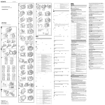
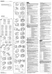
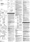
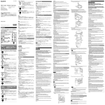
4-134-920-01(1) HDR-CX12/CX11/CX7/CX6 D -5-F Sports Pack Preparation Guide Guide de préparation du caisson sport 2 Coat the front glass with anti-fogging lens solution. Apply 2 to 3 drops of the anti-fogging lens solution provided onto the inside surface of the front glass of the sports pack. To increase the anti-fogging effect, use the desiccant supplied. For details, refer to “Desiccant” in the supplied operating instructions. 3 Remove foreign materials such as dust, sand or hair from the O-ring, the groove and any surface it touches. Then, put the grease evenly on the O-ring. HDR-UX20/UX19/UX10/UX9 DCR-DVD910/DVD510 -5-G -4 ➎㣖㌊㠓#ⷪ⌮#ცⱞᧆ If the body is closed with such materials present, these areas may be damaged and water may leak in. For details on handling the O-ring, refer to the “Handling the O-ring” in the operating instructions. E 1 HDR-HC9/HC7/HC5 MC Align the screw position of the mounting shoe with the tripod screw on the bottom of the video camera. When using the models below, open the jack cover and firmly insert the Audio/ Remote plug into the A/V jack, A/V OUT jack or A/V remote jack: HDR-UX20/UX19/UX10/UX9, DCR-DVD910/DVD510, DCR-SR87/SR77/SR67/ SR57/SR48/SR47/SR38/SR37, DCR-SX60/SX50/SX41/SX40/SX31/SX30 When using the DCR-SR87/SR77/SR67/SR57/SR48/SR47/SR38/SR37, insert the Audio/Remote plug with sufficient opening of the jack cover. (See illustration -5-I ) As insufficient opening of the jack cover, the jack cover jams the Audio/Remote plug, and causes poor connection. Attach the camera mounting shoe to the video camera using the metal parts of shoulder strap as shown in the illustration. -5-H ND DCR-SR87/SR77/SR67/SR57/SR48/SR47/SR38/SR37 -5-I -4 2 4 Attach the camera mounting shoe. 3 F 5 Connect the plug and install the video camera. Depending on your video camera, firmly insert the Audio/Remote plug into the A/V jack, A/V OUT jack or A/V remote jack. (except video camera models in step 4) When installing the video camera into the sports pack, align the camera mounting shoe with the guide inside the front body of the sports pack, and then push the rear of the camera mounting shoe until it clicks into place. 4 Notes DCR-SR85/SR75/SR65/SR55/SR46/SR45/SR36/SR35 -5-J SPK-HCE © 2009 Sony Corporation Printed in Japan M30 30 47 (M30 50) (M30 58) M30 62 G D F H 43 M37 55 DCR-SX60/SX50/SX41/SX40/SX31/SX30 -4 HDR-UX20/UX19/UX10/UX9, DCR-DVD910/DVD708/DVD608/DVD510/ DVD308/DVD306/DVD109/DVD108/ DVD106, DCR-HC62/HC54/HC53/HC52/HC51/ HC48/HC47/HC45/HC38/HC37 HDR-CX120/CX106/CX105/CX100, DCR-SR87/SR77/SR67/SR57/SR48/SR47/ SR38/SR37 DCR-DVD850/DVD810/DVD710/DVD650/ DVD610/DVD450/DVD410/DVD310/ DVD150/DVD115/DVD110 DCR-SR85/SR75/SR65/SR55/SR46/SR45/ SR36/SR35 HDR-XR200V/XR200/XR106/XR105/XR101/ XR100, HDR-SR10, DCR-SR220/SR210 HDR-XR520V/XR520/XR500V/XR500, HDR-SR12/SR11/SR8/SR7/SR5, HDR-CX12/CX11/CX7/CX6, HDR-HC9/HC7/HC5 DCR-SX60/SX50/SX41/SX40/SX31/SX30 DCR-DVD850/DVD810/DVD710/DVD650/DVD610/DVD450/DVD410/ -5-L DVD310/DVD150/DVD115/DVD110 G DCR-DVD708/DVD608/DVD308/DVD306/DVD109/DVD108/DVD106 -5-M DCR-HC62/HC54/HC53/HC52/HC51/HC48/HC47/HC45/HC38/HC37 -5-N 6 H 2 J F 1 2 G 1 H 1 I 1 J 1 K 1 K J 1 HDR-HC9/HC7/HC5 DCR-DVD708/DVD608/DVD308/DVD306/ DVD109/DVD108/DVD106 DCR-HC62/HC54/HC53/HC52/HC51/HC48/ HC47/HC45/HC38/HC37 HDR-CX12/CX11/CX7/CX6 HDR-SR8/SR7/SR5 HDR-UX20/UX19/UX10/UX9, DCR-DVD910/DVD850/DVD810/DVD710/ DVD650/DVD610/DVD510/DVD450/DVD410/ DVD310/DVD150/DVD115/DVD110 HDR-XR520V/XR520/XR500V/XR500/XR200V/ XR200/XR106/XR105/XR101/XR100, HDR-SR12/SR11/SR10, DCR-SR220/SR210 DCR-SR85/SR75/SR65/SR55/SR46/SR45/SR36/ SR35 HDR-CX120/CX106/CX105/CX100, DCR-SX60/SX50/SX41/SX40/SX31/SX30 DCR-SR87/SR77/SR67/SR57/SR48/SR47/SR38/ SR37 1 D I English Preparing Notes The video camera models described below may not be available in all countries/regions. Preparing the Video Camera For details, please refer to the operating instructions supplied with your video camera. 1 Remove filter, conversion lens, lens cap, lens hood or the shoulder strap from the video camera. When using a video camera with a manual lens shutter, open the lens shutter. 2 Install the battery pack. Attach a fully recharged battery. 3 Insert the media. Insert a media compatible with your video camera. For details, refer to the operating instructions supplied with your video camera. 2 Notes Unlock the safety tab on the “Memory Stick Duo” media and the cassette tape, and make them possible to record images. Be sure that the tape, “Memory Stick Duo” media, disc and hard disk and internal memory have enough space to record images. Be sure that the disc is not finalized. H 2 1 START/STOP K 4 Attach the reflex prevention ring to the filter attachment screw of the video camera. PHOTO The reflex prevention ring prevents external light from being reflected inside the sports pack and entering the lens. When using a video camera without a reflex prevention ring, turn your back away from the sunlight as much as possible. 2 1 1 2 Reflex prevention ring (M30 × ø 43) POWER ON/OFF Reflex prevention ring OFF ON/OFF OFF L Reflex prevention ring (M30 × ø 47) Reflex prevention ring (M30 × ø 50) Reflex prevention ring (M30 × ø 58) 2 3 O 4 O 4 N Reflex prevention ring (M30 × ø 62) Reflex prevention ring (M37 × ø 55) 3 O M 1 Unable to attach the supplied reflex prevention ring O / A/V A/V OUT A/V HDR-UX20/UX19/UX10/UX9 DCR-DVD910/DVD510 DCR-SR87/ SR77/SR67/SR57/SR48/SR47/SR38/SR37 DCR-SX60/SX50/SX41/SX40/ SX31/SX30 DCR-SR87/SR77/SR67/SR57/SR48/SR47/SR38/SR37 -5-I / A 1 Choose the mounting shoe and the number according to the table below. D A/V OUT / A/V A/V 4 F G B H ON/OFF / I HDR-XR520V/XR520/XR500V/XR500 -5-A Camera mounting shoe Sabot de montage de caméra C ឹኈᐡԋ၇྄ቻ ㍞Ἶᱦ#Ẳ⮞㟯#❲ Ᏻक़ ცⱞᧆ ឹኈᐡԋ၇྄ቻ єᡞ ⇢㆞ ㍞Ἶᱦ#Ẳ⮞㟯#❲ Ᏻक़ Body Corps ცⱞᧆ єᡞ ⇢㆞ Guide Guide ㍞Ἶᱦ#Ẳ⮞㟯#❲ Ᏻक़ ცⱞᧆ єᡞ ⇢㆞ The tripod screw plate is attached to the mounting shoe H when the unit is shipped from the factory. HDR-XR200V/XR200/XR106/XR105/XR101/XR100 -5-B Preparing the Sports Pack 1 Adjust the grip strap. Holding the sports pack so that the tips of your finger can easily touch the START/ STOP button, Telephoto button, Wide button and PHOTO button, adjust its length. 2 Attach the shoulder strap. HDR-SR12/SR11/SR10 DCR-SR220/SR210 -5-C HDR-CX120/CX106/CX105/CX100 Installing the Video Camera When using a video camera with a POWER switch, turn the POWER switch off and also leave the power of the sports pack turned off. When using a video camera with an internal power switch linked to the switching action of the LCD screen, you do not need to turn off the video camera. HDR-SR8/SR7/SR5 Number Video camera HDR-HC9/HC7/HC5, 1 DCR-DVD708/DVD608/DVD308/DVD306/ DVD109/DVD108/DVD106 DCR-HC62/HC54/HC53/HC52/HC51/HC48/HC47/ 2 HC45/HC38/HC37 1 HDR-CX12/CX11/CX7/CX6 2 HDR-SR8/SR7/SR5 HDR-UX20/UX19/UX10/UX9, DCR-DVD910/DVD850/DVD810/DVD710/DVD650/ 1 DVD610/DVD510/DVD450/DVD410/DVD310/ DVD150/DVD115/DVD110 HDR-XR520V/XR520/XR500V/XR500/XR200V/ XR200/XR106/XR105/XR101/XR100, 1 HDR-SR12/SR11/SR10, DCR-SR220/SR210 1 DCR-SR85/SR75/SR65/SR55/SR46/SR45/SR36/SR35 HDR-CX120/CX106/CX105/CX100, 1 DCR-SX60/SX50/SX41/SX40/SX31/SX30 1 DCR-SR87/SR77/SR67/SR57/SR48/SR47/SR38/SR37 2 Align the tripod screw plate with the chosen number on the mounting shoe and press the tripod screw plate until it clicks into place. ឹኈᐡԋ၇྄ቻ J K HDR-XR200V/XR200/XR106/XR105/XR101/XR100, HDR-SR10, DCR-SR220/SR210 HDR-XR520V/XR520/XR500V/XR500, HDR-SR12/SR11/SR8/SR7/SR5, HDR-CX12/CX11/CX7/CX6, HDR-HC9/HC7/HC5 DCR-SX60/SX50/SX41/SX40/SX31/SX30 Selecting the Camera Mounting Shoe Mounting shoe 5 Video camera HDR-UX20/UX19/UX10/UX9, DCR-DVD910/DVD708/DVD608/DVD510/DVD308/ DVD306/DVD109/DVD108/DVD106, DCR-HC62/HC54/HC53/HC52/HC51/HC48/HC47/ HC45/HC38/HC37 HDR-CX120/CX106/CX105/CX100, DCR-SR87/SR77/SR67/SR57/SR48/SR47/SR38/SR37 DCR-DVD850/DVD810/DVD710/DVD650/DVD610/ DVD450/DVD410/DVD310/DVD150/DVD115/DVD110 DCR-SR85/SR75/SR65/SR55/SR46/SR45/SR36/SR35 5 Turn the LCD panel over and move back to the video camera with the LCD screen facing out. 6 Set the functions, such as focusing and lightning, to AUTO. 5 -5-K 5 6 I -5-D Notes After installing the video camera into the sports pack, you can set the power of the video camera to “ON” or “OFF” by pressing the POWER button of the sports pack. 1 Release the buckles. -5-E Keep sliding the unlock button in the direction of the arrow, slide the open slider and release the buckle. Open the rear body. Be sure to keep the sports pack horizontal when installing the camera mounting shoe. Installing the camera mounting shoe in a vertical motion may damage the camera mounting shoe and the front body. Be sure not to cover the lens, LCD screen, view finder, zoom lever or photo button with the cable. When using a video camera with an internal power switch linked to the switching action of the LCD screen, connecting the Audio/Remote plug will switch the Still image recording mode/Video playing mode to the Movie recording mode of the video camera. When using HDR-XR520V/XR520/XR500V/XR500 (See illustration -5-A) Open the jack cover and connect the plug. (Place the cable connected to the sports pack with the plug to the rear in a circular motion as illustrated.) Install the video camera into the sports pack, taking care not to catch the cable on the parts inside the sports pack. After installing the video camera into the sports pack, arrange the cable on the grip belt side of the video camera. When using HDR-XR200V/XR200/XR106/XR105/XR101/XR100 (See illustration -5-B) Open the jack cover and connect the plug. Place the cable connected to the sports pack with the plug to the rear in a circular motion as illustrated. Install the video camera into the sports pack, taking care not to catch the cable on the parts inside the sports pack. After installing the video camera into the sports pack, arrange the cable on the grip belt side of the video camera. When using HDR-SR12/SR11/SR10, DCR-SR220/SR210 (See illustration -5-C) Open the jack cover and connect the plug. (Place the cable connected to the sports pack with the plug to the rear in a circular motion as illustrated.) After installing the video camera into the sports pack, arrange the cable on the grip belt side of the video camera by pushing it lightly. When using HDR-SR8/SR7/SR5 (See illustration -5-D) Open the jack cover. Connect the plug. After installing the video camera into the sports pack, arrange the cable on the grip belt side of the video camera. When using HDR-CX120/CX106/CX105/CX100 (See illustration -5-E) Open the jack cover and connect the plug. After installing the video camera into the sports pack, arrange the cable on the grip belt side of the video camera, taking care not to catch the cable on the camera mounting shoe or other parts. When using HDR-CX12/CX11/CX7/CX6 (See illustration -5-F) Open the jack cover. Connect the plug. Put the cable on the camera mounting shoe and install the video camera into the sports pack. After installing the video camera into the sports pack, arrange the cable so that it will not fall out of the camera mounting shoe. Set the cable on the grip belt side of the video camera. When using HDR-UX20/UX19/UX10/UX9 or DCR-DVD910/DVD510 (See illustration -5-G) (If you completed the following and in step -4, start from .) Connect the plug. Attach the camera mounting shoe to the video camera. After installing the video camera into the sports pack, adjust the cable. (Hook the cable at the cable holder.) When using HDR-HC9/HC7/HC5 (See illustration -5-H) Open the jack cover. Connect the plug. After installing the video camera into the sports pack, arrange the cable on the grip belt side of the video camera. When using DCR-SR87/SR77/SR67/SR57/SR48/SR47/SR38/SR37 (See illustration -5-I) (If you completed the following and in step -4, start from .) Attach the plug by adequately opening the jack cover so that it does not become attached to the base of the plug. Attach the camera mounting shoe to the video camera. Install the video camera into the sports pack, keeping the cable on the top side of the video camera. Secure the cable in the clip of the camera mounting shoe, taking care not to catch the cable on the LCD screen. If the video camera battery is large and the cable cannot be passed around the backside of it, fasten the cable with clips after passing the battery around the top side of it. When using DCR-SR85/SR75/SR65/SR55/SR46/SR45/SR36/SR35 (See illustration -5-J) Open the jack cover and connect the plug. (Place the cable connected to the sports pack with the plug to the rear in a circular motion as illustrated.) After installing the video camera into the sports pack, arrange the cable on the grip belt side of the video camera by pushing it lightly. When using DCR-SX60/SX50/SX41/SX40/SX31/SX30 (See illustration -5-K) (If you completed the following and in step -4, start from .) Lift the grip belt and open the jack cover to connect the plug. Attach the camera mounting shoe to the video camera. Install the video camera into the sports pack, keeping the cable bending on the top side of the video camera. After installing the video camera into the sports pack, adjust the cable. (Hook the cable at the cable holder.) When using DCR-DVD850/DVD810/DVD710/DVD650/DVD610/DVD450/ DVD410/DVD310/DVD150/DVD115/DVD110 (See illustration -5-L) Open the jack cover. Connect the plug. Clip the cable with the groove of the reflex prevention ring on the grip belt side as illustrated. Place the cable as illustrated and attach the camera mounting shoe to the sports pack. Notes on attachment: Do not bend the cable. Be sure that the cable has not come off the groove of the reflex prevention ring. After installing the video camera into the sports pack, be sure that the cable is not interfering with the lens of the video camera. When using DCR-DVD708/DVD608/DVD308/DVD306/DVD109/DVD108/ DVD106 (See illustration -5-M) Open the jack cover. Connect the plug. After installing the video camera into the sports pack, adjust the cable. (See illustration) When using the DCR-HC62/HC54/HC53/HC52/HC51/HC48/HC47/HC45/HC38/ HC37 (See illustration -5-N) Open the jack cover. Connect the plug. After installing the video camera into the sports pack, adjust the cable. (Hook the cable at the cable holder.) 6 Close the rear body. Press the rear body shut, and fasten the buckles until they click in place. Notes Be careful not to pinch the cables when closing the rear body. Although the center of the lens of some video camera models may be out of line with the center of the front glass of the sports pack when installed, this will not cause any problems when recording. Français Préparation Remarques Les modèles de caméscopes mentionnés ci-dessous ne sont pas forcément disponibles dans tous les pays ou toutes les régions. Préparation du caméscope Pour le détail, reportez-vous au mode d’emploi fourni avec votre caméscope. 1 Retirez le filtre, le convertisseur, le capuchon d’objectif, le pare-soleil ou la bandoulière du caméscope. Si le caméscope que vous utilisez est pourvu d’un obturateur central manuel, ouvrez cet obturateur. 2 Installez la batterie. Installez une batterie complètement rechargée. 3 Introduisez le support. Introduisez un support compatible avec votre caméscope. Pour plus d’informations, reportez-vous au mode d’emploi fourni avec le caméscope. Remarques Désactivez le taquet de sécurité du « Memory Stick Duo » et de la cassette pour permettre l’enregistrement. Assurez-vous que l’espace sur la cassette, le « Memory Stick Duo », le disque et le disque dur ainsi que dans la mémoire interne est suffisant pour l’enregistrement. Assurez-vous que le disque n’a pas été finalisé. 4 Fixez la bague antireflet sur le filetage de l’objectif du caméscope. La bague antireflet empêche la lumière extérieure de se réfléchir dans le caisson sport et de pénétrer dans l’objectif. Si vous utilisez un caméscope avec une bague antireflet, ne filmez pas si possible avec le soleil derrière vous. (Suite á la page arrière) ʕ 5 ʔ Fixez le sabot de montage de caméra au caméscope. Installez le caméscope dans le caisson sport en laissant le câble sur le caméscope. Accrochez le câble à l’aide de l’attache du sabot de montage de caméra, en prenant soin de ne pas le coincer sur l’écran LCD. Si la batterie du caméscope est trop grosse et si vous ne pouvez pas faire passer le câble à l’arrière de la batterie, fixez-le avec des attaches après avoir fait passer la batterie par dessus. Lorsque les DCR-SR85/SR75/SR65/SR55/SR46/SR45/SR36/SR35 sont utilisés (Voir l’illustration -5-J) Ouvrez le cache-prise et branchez la fiche. (Faites revenir le câble raccordé au caisson sport par la fiche vers l’arrière en formant une fermoir, comme indiqué dans l’illustration.) Après avoir installé le caméscope dans le caisson sport, rangez le câble du côté de la sangle du caméscope en le poussant doucement. Lorsque les DCR-SX60/SX50/SX41/SX40/SX31/SX30 sont utilisés (Voir l’ illustration -5-K) (Si les points et suivants ont déjà été effectués à l’étape -4, continuez par .) Levez la sangle et ouvrez le cache-borne pour brancher la prise. Fixez le sabot de montage de caméra au caméscope. Installez le caméscope dans le caisson sport en lmaintenant le câble courbé sur le caméscope. Après avoir installé le caméscope dans le caisson sport, ajustez le câble. (Accrochez le câble au support de câble.) Lorsque les DCR-DVD850/DVD810/DVD710/DVD650/DVD610/DVD450/ DVD410/DVD310/DVD150/DVD115/DVD110 sont utilisés (Voir l’illustration -5-L) Ouvrez le cache-prise. Branchez la prise. Insérez le câble dans la rainure de la bague antireflet du côté de la sangle, comme indiqué sur l’illustration. Disposez le câble de la façon illustrée et fixez le sabot de montage de caméra au caisson sport. Remarques sur le câble : Ne tordez pas le câble. Veillez à ce que le câble ne ressorte pas de la rainure de la bague antireflet. Après avoir installé le caméscope dans le caisson sport, veillez à ce que le câble ne gêne pas l’objectif du caméscope. Lorsque les DCR-DVD708/DVD608/DVD308/DVD306/DVD109/DVD108/ DVD106 sont utilisés (Voir l’illustration -5-M) Ouvrez le cache-prise. Branchez la prise. Après avoir installé le caméscope dans le caisson sport, ajustez le câble. (Voir l’illustration) Lorsque les DCR-HC62/HC54/HC53/HC52/HC51/HC48/HC47/HC45/HC38/ HC37 sont utilisés (Voir l’illustration -5-N) Ouvrez le cache-prise. Branchez la prise. Après avoir installé le caméscope dans le caisson sport, ajustez le câble. (Accrochez le câble au support de câble.) Français (Suite de la page avant) Bague antireflet Bague antireflet (M30 × ø 43) Bague antireflet (M30 × ø 47) Bague antireflet (M30 × ø 50) Bague antireflet (M30 × ø 58) Caméscope HDR-UX20/UX19/UX10/UX9, DCR-DVD910/DVD708/DVD608/DVD510/DVD308/ DVD306/DVD109/DVD108/DVD106, DCR-HC62/HC54/HC53/HC52/HC51/HC48/HC47/ HC45/HC38/HC37 HDR-CX120/CX106/CX105/CX100, DCR-SR87/SR77/SR67/SR57/SR48/SR47/SR38/SR37 DCR-DVD850/DVD810/DVD710/DVD650/DVD610/ DVD450/DVD410/DVD310/DVD150/DVD115/DVD110 DCR-SR85/SR75/SR65/SR55/SR46/SR45/SR36/SR35 HDR-XR200V/XR200/XR106/XR105/XR101/XR100, Bague antireflet HDR-SR10, (M30 × ø 62) DCR-SR220/SR210 HDR-XR520V/XR520/XR500V/XR500, Bague antireflet HDR-SR12/SR11/SR8/SR7/SR5, (M37 × ø 55) HDR-CX12/CX11/CX7/CX6, HDR-HC9/HC7/HC5 Impossible de fixer la bague DCR-SX60/SX50/SX41/SX40/SX31/SX30 antireflet fournie 5 Retournez le panneau de l’écran LCD et rabattez-le contre le caméscope avec l’écran LCD tourné vers l’extérieur. 6 Réglez la mise au point, l’éclairage, etc. sur AUTO. Sélection du sabot de montage de caméra 1 Choisissez le sabot de montage et le numéro d’orifice en vous reportant au tableau suivant. Sabot de montage Numéro Caméscope HDR-HC9/HC7/HC5, 1 DCR-DVD708/DVD608/DVD308/DVD306/ DVD109/DVD108/DVD106 D DCR-HC62/HC54/HC53/HC52/HC51/HC48/HC47/ 2 HC45/HC38/HC37 1 HDR-CX12/CX11/CX7/CX6 F 2 HDR-SR8/SR7/SR5 HDR-UX20/UX19/UX10/UX9, DCR-DVD910/DVD850/DVD810/DVD710/DVD650/ G 1 DVD610/DVD510/DVD450/DVD410/DVD310/ DVD150/DVD115/DVD110 HDR-XR520V/XR520/XR500V/XR500/XR200V/ XR200/XR106/XR105/XR101/XR100, H 1 HDR-SR12/SR11/SR10, DCR-SR220/SR210 I 1 DCR-SR85/SR75/SR65/SR55/SR46/SR45/SR36/SR35 HDR-CX120/CX106/CX105/CX100, J 1 DCR-SX60/SX50/SX41/SX40/SX31/SX30 K 1 DCR-SR87/SR77/SR67/SR57/SR48/SR47/SR38/SR37 ˎ ˎ ˎ ʓ ʔ ʕ ʓ ʖ ʔ ʕ 2 6 5 Raccordez la fiche et installez le caméscope. Insérez fermement la fiche Audio/Télécommande dans la prise A/V, A/V OUT ou la prise de télécommande A/V selon le caméscope utilisé. (sauf modèles de caméscopes mentionnés au point 4) Lorsque vous installez le caméscope dans le caisson sport, alignez le sabot de montage de caméra sur le guide dans la partie avant du caisson sport, puis poussez l’arrière du sabot de montage de caméra jusqu’à ce que le sabot s’encliquette. 4 1 ʓ ʔ ʕ 2 6 ⢻ᾋ゛#㣫Ⓥ⇳ HDR-UX20/UX19/UX10/UX9, DCR-DVD910/DVD708/DVD608/DVD510/DVD308/ DVD306/DVD109/DVD108/DVD106, DCR-HC62/HC54/HC53/HC52/HC51/HC48/HC47/ HC45/HC38/HC37 ⚏⬣#⚠㐷# ʓ ʔ Ȑ-4 ʕ +P63#啑#堬#76, HDR-CX120/CX106/CX105/CX100, DCR-SR87/SR77/SR67/SR57/SR48/SR47/SR38/SR37 ⚏⬣#⚠㐷# +P63#啑#堬#7:, ⚏⬣#⚠㐷# Ȑ-5-H DCR-DVD850/DVD810/DVD710/DVD650/DVD610/ DVD450/DVD410/DVD310/DVD150/DVD115/DVD110 +P63#啑#堬#83, ⚏⬣#⚠㐷# DCR-SR85/SR75/SR65/SR55/SR46/SR45/SR36/SR35 +P63#啑#堬#8;, ʓ ʔ Ȑ-4 HDR-XR200V/XR200/XR106/XR105/XR101/XR100, HDR-SR10, +P63#啑#堬#95, DCR-SR220/SR210 HDR-XR520V/XR520/XR500V/XR500, ⚏⬣#⚠㐷# HDR-SR12/SR11/SR8/SR7/SR5, HDR-CX12/CX11/CX7/CX6, +P6:#啑#堬#88, HDR-HC9/HC7/HC5 Ṑ ➀ ẓ # ⚏ ⬣ # ⚠ 㐷 # ㆻ# DCR-SX60/SX50/SX41/SX40/SX31/SX30 ʕ ⚏⬣#⚠㐷# ˎ ⟷㚠㿗#ⲏ#〽ᴿᵛ 5# OFG# 㠒ᗺⰮ# ℂᵆ# ᢶᴎ☆# OFG# 㬾ⱞ# ፏ⾧Ⱞ# 㪏㩂ᵇ# ⌮᧾⬎# ㍞Ἶᱦ#⾧⪺#ᤂᢶᴎ#ᙽ➟ឲ៎1 Ȑ-5-K ʓ ʔ Ȑ-4 6# ㇲ⳺ⱞᖂ#ⵚὯ#ⱂ#ጚតⰮ#DXWRᵆ#☎⳿㩓ឲ៎1 Ȏ#㍞Ἶᱦ#Ẳ⮞㟯#❲#☊㗇㩂ጚ ʕ 1# ៎ⰶ#㥆⪺☆#Ẳ⮞㟯#❲⬪#ⅲ㬢Ṧ#☊㗇㩓ឲ៎1 Ȑ-5-M ㄫ㵼#⳿ Ȑ-5-L D ⛿䂯 1 2 Ȑ-5-N ˎ ˎ F 1 2 G 1 H 1 I 1 J 1 K 1 Ȑ-5-M Ȑ-5-N ⢻ᾋ゛#㣫Ⓥ⇳ HDR-HC9/HC7/HC5, DCR-DVD708/DVD608/DVD308/DVD306/ DVD109/DVD108/DVD106 DCR-HC62/HC54/HC53/HC52/HC51/HC48/HC47/ HC45/HC38/HC37 HDR-CX12/CX11/CX7/CX6 HDR-SR8/SR7/SR5 HDR-UX20/UX19/UX10/UX9, DCR-DVD910/DVD850/DVD810/DVD710/DVD650/ DVD610/DVD510/DVD450/DVD410/DVD310/ DVD150/DVD115/DVD110 HDR-XR520V/XR520/XR500V/XR500/XR200V/ XR200/XR106/XR105/XR101/XR100, HDR-SR12/SR11/SR10, DCR-SR220/SR210 DCR-SR85/SR75/SR65/SR55/SR46/SR45/SR36/SR35 HDR-CX120/CX106/CX105/CX100, DCR-SX60/SX50/SX41/SX40/SX31/SX30 DCR-SR87/SR77/SR67/SR57/SR48/SR47/SR38/SR37 2# ▦ძ# ᖂ▖# 㧶ᳲⱞ㞢Ṧ# Ẳ⮞㟯# ❲ⱂ# ☊㗇㩆# ⅲ㬢⪺# Ỉ㉾ᇊ/# ⪞ც# ♶ẖც#ᖊ#ᨶጶ⺪#▦ძ#ᖂ▖#㧶ᳲⱞ㞢Ṧ#ᛮṯឲ៎1 ᝬ㈜#㠓㿏#ⵓ#⬳ᙸᵷ#ᬏ⬣#㾃≿㴯ᴋ#ㄫ㵼#⳿#Kぇ#㈜㚠ẏ〫#ㇿᴿᵛ1 ˎ ˎ ȏ#➎㣖㌊㠓#ⷪ⌮㩂ጚ 1# ዢầ#➎㞢ᲓⰮ#ⵚⳲ㩓ឲ៎1 VWDUW2VWRS#⛻㴳/#Whohskrwr#⛻㴳/#Zlgh#⛻㴳/#SKRWR#⛻㴳ㆻ#Ⰷᙷ⇴ㆳ⋓# ㋧㈈㿏ᢧ#ḻ⋔#ⴛ㹣㢗㶠ㆻ#㈘/#ᡯ#ⴛ㴯∠㇏#⏳#㋧㉿㿏っ#㍳ⵤⵓ゛1 4 2# ⪞ፒ#ᔲⰮ#ⲏㄓ㩓ឲ៎1 Ȑ#⌮᧾⬎#㍞Ἶᱦ#ⲏㄓ㩂ጚ SRZHU#ⴛㅻ㣏ᙷ#ㇿᴋ#⢻ᾋ゛#㣫Ⓥ⇳⏳#⬣ㄠ㿏ᴋ#᜴ㄧぇᴋ#SRZHU#ⴛㅻ㣏⏳#᪻/# ⴛ㹣㢗㶠㇏#㉻ㅇḻ#ᪿ#⬸㭓⋓#㆗㐷㿫#㍳ⵤⵓ゛1#OFG#䃋⓫㇏#㉻ㅇᮚᢧ#㋧㈈ぇ#でẓ# ᬫ⟷#㉻ㅇ#ⴛㅻ㣏ᙷ#ㇿᴋ#⢻ᾋ゛#㣫Ⓥ⇳⏳#⬣ㄠ㿗#ῃぇᴋ#⢻ᾋ゛#㣫Ⓥ⇳㇏#㉻ㅇㆻ#᫃# 㾻ㄋᙷ#〽ᴿᵛ1 ⷦⱂ⳺ ⴛ㹣㢗㶠ぇ#⢻ᾋ゛#㣫Ⓥ⇳⏳#㈜㚠㿓#䄻ᴋ#ⴛ㹣㢗㶠㇏#SRZHU#⛻㴳ㆻ#ᱻ⏫#⢻ᾋ゛# 㣫Ⓥ⇳㇏#㉻ㅇㆻ#啂RQ啃#₇ᴋ#啂RII啃⋓#⮛㊌㿗#ⲏ#ㇿᴿᵛ1 1# Ⅾ㕞Ⱞ#㥳ឲ៎1 ʓ ㈗#㿫㊓#⛻㴳#ɞㆻ#䃋⬫㻓#⚠䀜ㆳ⋓#♳#㚻#゛㽿#ⴣ⇳᷋#ɟ⏳#♷〫⮓#⛻㫫ㆻ# 㼀ᴿᵛ1 ʔ Ἦ⓫#❯㜫⏳#ぴᴿᵛ1 5 6 2# ⩈#Ⰺẖ⪺#➟ጚ#ℓ⺪#ᳶ#⮓⩋Ⱞ#ṯឲ៎1 ⟷Ⰴẓ#ᢧ#⚠㐷#⊃㏿#ㄠ#5/#6#⚠ㄯㆻ#ⴛ㹣㢗㶠㇏#⿕#㆗␣#⾿㔴ぇ#⚋⏼ᴿᵛ1#ᢧ# ⚠㐷# 䄟ᝳ⏳# ᰉㇳ# ⲏ# ㇿḻ⋔# ⟷Ⰴẓ# ᛫㋧㊓⏳# ⬣ㄠ㿏っ# ㍳ⵤⵓ゛1# ㈇⮯㿓# ᬫㄠㆷ# ⟷Ⰴẓ#⮛⓼⮓㇏#%᛫㋧㊓%⏳#㚯㋧㿏っ#㍳ⵤⵓ゛1 Ȏ 1 3# Rẫⱞᖂ#㬲##ዢ#℀ⱂ#⳻ㇳ⪺☆#ἦ⺪ᖂ#ᾒᲂ/#ἢẖ㍞ᱧ#ⱂ#ⱞ…⺲Ⱞ# ⴆᅚ㩓ឲ៎1#ዢẖᇊ#Rẫ⪺#ዢẖ➎Ṧ#ᇊṞᅶ#㢞#ṯឲ៎1 Remarques Veillez à tenir le caisson sport à l’horizontale lorsque vous installez le sabot de montage de caméra. Si vous installez le sabot de montage de caméra en inclinant le caméscope, vous risquez d’endommager le sabot ainsi que la partie avant du caisson sport. Attention de ne pas masquer l’objectif, l’écran LCD, le viseur, le levier de zoom ou le bouton photo avec le câble. Lorsque vous utilisez un caméscope avec interrupteur d’alimentation relié à la fonction de commutation de l’écran LCD, le branchement de la fiche Audio/ Télécommande fera basculer le mode d’enregistrement de photos/mode de lecture vidéo dans le mode d’enregistrement de film du caméscope. Lorsque les HDR-XR520V/XR520/XR500V/XR500 sont utilisés (Voir l’illustration -5-A) Ouvrez le cache-prise et branchez la fiche. (Faites revenir le câble raccordé au caisson sport par la fiche vers l’arrière en formant une boucle, comme indiqué dans l’illustration.) Installez le caméscope dans le caisson sport, en prenant soin de ne pas coincer le câble dans les pièces à l’intérieur du caisson sport. Après avoir installé le caméscope dans le caisson sport, rangez le câble du côté de la sangle du caméscope. Lorsque les HDR-XR200V/XR200/XR106/XR105/XR101/XR100 sont utilisés (Voir l’illustration -5-B) Ouvrez le cache-prise et branchez la fiche. Faites revenir le câble raccordé au caisson sport par la fiche vers l’arrière en formant une boucle, comme indiqué dans l’illustration.) Installez le caméscope dans le caisson sport, en prenant soin de ne pas coincer le câble dans les pièces à l’intérieur du caisson sport. Après avoir installé le caméscope dans le caisson sport, rangez le câble du côté de la sangle du caméscope. Lorsque les HDR-SR12/SR11/SR10, DCR-SR220/SR210 sont utilisés (Voir l’ illustration -5-C) Ouvrez le cache-prise et branchez la fiche. (Faites revenir le câble raccordé au caisson sport par la fiche vers l’arrière en formant une fermoir, comme indiqué dans l’illustration.) Après avoir installé le caméscope dans le caisson sport, rangez le câble du côté de la sangle du caméscope en le poussant doucement. Lorsque les HDR-SR8/SR7/SR5 sont utilisés (Voir l’illustration -5-D) Ouvrez le cache-prise. Branchez la prise. Après avoir installé le caméscope dans le caisson sport, rangez le câble du côté de la sangle du caméscope. Lorsque les HDR-CX120/CX106/CX105/CX100 sont utilisés (Voir l’illustration -5-E) Ouvrez le cache-prise et branchez la fiche. Après avoir installé le caméscope dans le caisson sport, rangez le câble du côté de la sangle du caméscope en prenant soin de ne pas coincer le câble sur le sabot de montage de caméra ou d’autres pièces. Lorsque les HDR-CX12/CX11/CX7/CX6 sont utilisés (Voir l’illustration -5-F) Ouvrez le cache-prise. Branchez la prise. Placez le câble sur le sabot de montage de caméra et installez le caméscope dans le caisson sport. Après avoir installé le caméscope dans le caisson sport, disposez le câble de sorte qu’il ne tombe pas du sabot de montage de caméra. Rangez ensuite le câble du côté de la sangle du caméscope. Lorsque les HDR-UX20/UX19/UX10/UX9 ou DCR-DVD910/DVD510 sont utilisés (Voir l’illustration -5-G) (Si les points et suivants ont déjà été effectués à l’étape -4, continuez par .) Branchez la prise. Fixez le sabot de montage de caméra au caméscope. Après avoir installé le caméscope dans le caisson sport, ajustez le câble. (Accrochez le câble au support de câble.) Lorsque les HDR-HC9/HC7/HC5 sont utilisés (Voir l’illustration -5-H) Ouvrez le cache-prise. Branchez la prise. Après avoir installé le caméscope dans le caisson sport, rangez le câble du côté de la sangle du caméscope. Lorsque les DCR-SR87/SR77/SR67/SR57/SR48/SR47/SR38/SR37 sont utilisés (Voir l’illustration -5-I) (Si les points et suivants ont déjà été effectués à l’étape -4, continuez par .) Fixez la fiche en ouvrant suffisamment le cache-prise pour qu’il ne se coince pas à la base de la fiche. ʗ ˎ ʓ ˎ ʔ ʕ 3 ⚏⬣# ⚠㐷# ㆷ# ワ⟷㇏# ⣒# ⴛ㹣㢗㶠# ᬫ⟷⋓# ⚏⬣ẏ〫# ⊃㏿⋓# Ὓ〫゛ᴋ# ㆻ# ⚠㐷㿠ᴿᵛ1 ⚏⬣#⚠㐷#〽#⢻ᾋ゛#㣫Ⓥ⇳⏳#⬣ㄠ㿏ᴋ#᜴ㄧぇᴋ#ᙷᴜ㿓㿓#㭓〈ㆻ#Ὠ㐻#⬸㭓⋓# 㞣へ㿫#㍳ⵤⵓ゛1 ⚏⬣#⚠㐷# ʓ 1 啂Phpru|#Vwlfn#Gxr啃#♯ᾋ〫シ#⢻ᾋ゛#㯃㽻㇏#⽧ᢧ㐷#㭤#㈗ㆻ#㿫㊓㿫⮓# ♯㐷⏳#ᢧ⋔㿗#ⲏ#ㇿᴋ#⬸㭓⋓#㿫#ᰊᴿᵛ1 㯃㽻/#啂Phpru|#Vwlfn#Gxr啃#♯ᾋ〫/#ᾋⴛ㫣#⚆#㿏ὓ#ᾋⴛ㫣シ#ᬫ㈜#Ⓥ┟␣ぇ# ♯㐷⏳#ᢧ⋔㿗#ⲏ#ㇿᴋ#㠠⟻㿓#ㄠ≀#ㇿᴋ㐷#䃌㇯㿏っ#㍳ⵤⵓ゛1 ᾋⴛ㫣ᙷ#㶃ᮇ⇳㏿#ẏ㐷#⿁⿏㇃ㆻ#䃌㇯㿏っ#㍳ⵤⵓ゛1 4# ℂ▖#ℓ⺪#ẫⰮ#⌮᧾⬎#㍞Ἶᱦⱂ#㨮㘚#ⲏㄓ#ᖂ▖⪺#ⲏㄓ㩓ឲ៎1 Ȑ-5-F Ȑ-5-J ʓ ʖ ʔ ˎ ˎ ʗ ʓ ʔ ʕ ʓ ʖ ʔ ʕ 4 Fixez le sabot de montage de caméra. Alignez la vis du sabot de montage sur le filetage de pied photo sous le caméscope. Si vous utilisez les modèles suivants, ouvrez le cache-prise et insérez à fond la fiche Audio/Télécommande dans la prise A/V, A/V OUT ou dans la prise de télécommande A/V : HDR-UX20/UX19/UX10/UX9, DCR-DVD910/DVD510, DCR-SR87/SR77/SR67/ SR57/SR48/SR47/SR38/SR37, DCR-SX60/SX50/SX41/SX40/SX31/SX30 Lorsque vous utilisez les DCR-SR87/SR77/SR67/SR57/SR48/SR47/SR38/SR37, ouvrez suffisamment le cache-prise pour pouvoir insérer la fiche Audio/ Télécommande. (Voir l’illustration -5-I) Si vous n’ouvrez pas suffisamment le cache-prise, celui-ci bloquera la fiche Audio/Télécommande et la connexion sera mauvaise. Fixez le sabot de montage de caméra au caméscope en utilisant les pièces métalliques de la bandoulière comme indiqué sur l’illustration. Ȑ-5-E Ȑ-5-I Veillez à ne pas coincer les câbles lorsque vous fermez la partie arrière. Bien que l’objectif de certains caméscopes puisse être décentré par rapport à la vitre avant du caisson, l’enregistrement s’effectue normalement. 3 Enlevez les matières étrangères, poussière, sable ou cheveux, du joint torique, de la rainure et de toutes les surfaces en contact avec le joint torique. Ensuite, graissez uniformément le joint torique. Si vous fermez le caisson sport sans nettoyer ces parties, celles-ci risquent d’être endommagées et de laisser l’eau pénétrer à l’intérieur. Pour le détail sur l’entretien du joint torique, reportez-vous à « Entretien du joint torique » dans le mode d’emploi. ⷦⱂ⳺ ʓ ʔ ʕ ʔ ʕ ʖ ⑃㠠㉻㿓#⚧㮧␣㶠ㆻ#㈜㚠㿏っ#㍳ⵤⵓ゛1 ⬣ㄠ#㎈㇯#⢻ᾋ゛#㣫Ⓥ⇳ぇ#ᵷ㇈㿏ᴋ#♯ᾋ〫⏳#ᮚ〫#㍳ⵤⵓ゛1 ㈇⮯㿓#ᬫㄠㆷ#⬣ㄠ#㎈㇯#⢻ᾋ゛#㣫Ⓥ⇳ぇ#⟷Ⰴẓ#⬣ㄠ⮛⓼⮓⏳#㚯㋧㿏っ#㍳ⵤⵓ゛1 Ȑ-5-D ʓ ʔ ʕ Remarques 2# ℚ㘚ẖ㠓Ⱞ#ⲏㄓ㩓ឲ៎1 3# ⃢᧾⪞Ṧ#ᘍ➟ឲ៎1 Ȑ-5-G Après avoir installé le caméscope dans le caisson sport, vous pouvez régler l’alimentation du caméscope sur « ON » ou « OFF » en appuyant sur le bouton POWER du caisson sport. Appliquez 2 ou 3 gouttes de la solution antibuée pour objectif fournie sur la face interne de la vitre avant du caisson sport. Afin d’augmenter l’effet antibuée, utilisez le dessiccatif fourni. Pour plus de détails, reportez-vous à « Dessiccatif » dans mode d’emploi fourni. Ȑ-5-C ʓ ʔ ʕ ʖ Remarques 2 Appliquez une solution antibuée pour objectif sur la vitre avant. ⲏṐ#⊃㏿#⯋㮧⏳#⬣ㄠ㿫⮓#⢻ᾋ゛#㣫Ⓥ⇳⏳#⬣ㄠ㿏ᴋ#᜴ㄧぇᴋ#⊃㏿#⯋㮧⏳#に〫# ㍳ⵤⵓ゛1 ʓ ʔ Appuyez sur la partie arrière du caisson pour le refermer et serrez les fermoirs jusqu’à ce qu’ils s’encliquettent. 3 1# ⌮᧾⬎# ㍞Ἶᱦ⪺☆# 㨮㘚/# ㏒Ⅾⳮ# ᳶ/# ᳶ# ㎋/# ᳶ# 㮮ᧆ# # ⪞ፒ# ᔲⰮ#≮ẖ㩓ឲ៎1 ʓ ʔ ʕ Tout en tenant le caisson sport de manière à atteindre facilement les boutons START/ STOP, Téléobjectif, Grand angle et PHOTO du bout des doigts, réglez la longueur de la sangle. Tout en poussant le bouton de déverrouillage dans le sens de la flèche, tirez sur le curseur et relâchez la fermoir. Ouvrez la partie arrière. ㈇⮯㿓#ᬫㄠㆷ#⬣ㄠ#㎈㇯#⢻ᾋ゛#㣫Ⓥ⇳ぇ#⟷Ⰴẓ#⬣ㄠ⮛⓼⮓⏳#㚯㋧㿏っ#㍳ⵤⵓ゛1 ʔ 1 Réglez la sangle. 1 Relâchez les fermoirs. ⌮᧾⬎#㍞Ἶᱦ#ⷪ⌮㩂ጚ ʓ 6 Ouvrez la partie arrière. ⷦⱂ⳺ ᵛ㇃ぇ# ᬏ㬷ᬯ# ⢻ᾋ゛# 㣫Ⓥ⇳# ┟ᷯㆷ# ㇳ⟷# ᬏ⇳2㐷つぇ⮓ᴋ# ⵓ㶇ẏ㐷# ⿁ㆻ# ⲏ# ㇿᴿᵛ1 Ȑ 5-B ʓ ʔ ʕ ʖ Préparation du caisson sport Lorsque vous utilisez un caméscope pourvu d’un interrupteur POWER, mettez l’ interrupteur POWER sur arrêt et laissez le caisson sport hors tension. Si vous utilisez un caméscope pourvu d’un interrrupteur d’alimentation interne relié à la fonction de commutation de l’écran LCD, vous n’avez pas besoin de mettre le caméscope hors tension. Ȑ-5-A ʔ ʕ La plaquette à vis a été fixée sur le sabot de montage H en usine. Installation du caméscope ⷪ⌮㩂ጚ ʓ 2 Emboîtez la plaquette à vis dans l’orifice choisi sur le sabot de montage, puis appuyez dessus de sorte qu’elle s’encliquette. 2 Fixez la bandoulière. 㩆⪞ △㐿ㆻ# ㊓ᛧ㿏㐷# ⿁# ❯㜫⏳# ᵢㆳ⓫# ᡯ# ⟷⟻# Ⰷ⬸ẏ# △# ⭇# び⊛ᙷ# ㇿᴿᵛ1 R ㇏# ㈇ ⮯ 㿓# 㡟 ᢀ ぇ# 㿫 ⮓ ᴋ# ⬣ ㄠ ⮛ ⓼ ⮓ ㇏# 啂R ㇏# 㡟 ᢀ啃ㆻ# 㚯 ㋧ 㿏 っ# ㍳ⵤⵓ゛1 4# ㍞Ἶᱦ#Ẳ⮞㟯#❲Ṧ#ⲏㄓ㩓ឲ៎1 ʓ ⢻ᾋ゛#㣫Ⓥ⇳#⚈⓫㇏#⬳ᙸᵷ#㈜㚠#ᬏ⬣ぇ#ㄫ㵼#⳿㇏#ᬏ⬣#ㅻ㣏⏳#㠋ⵤⵓ゛1 ʔ ⾻∏シ#ᚐㆷ#┟ᷯㆻ#⬣ㄠ㿏ᴋ#᜴ㄧぇᴋ#ᵟ㈇#㥛⛻⏳#に#゛ᾋ゛2␣┟㴯#㾃≣ᡯ ⏳#D2Y#ᵟ㈇/#D2Y#RXW#ᵟ㈇#₇ᴋ#D2Y#␣┟㴯#ᵟ㈇ぇ#ᵟᵟ䇿#⬴ㇼ㿫#㍳ⵤⵓ ゛= KGU0X[532X[4<2X[432X[</# GFU0GYG<432GYG843/# GFU0VU;:2 VU::2VU9:2VU8:2VU7;2VU7:2VU6;2VU6:/# GFU0V[932V[832V[742 V[732V[642V[63 ˎ GFU0VU;:2VU::2VU9:2VU8:2VU7;2VU7:2VU6;2VU6:ㆻ# ⬣ㄠ㿏ᴋ# ᜴ㄧ/# ᵟ㈇# 㥛⛻⏳# 㠠⟻䇿# に〫⮓# ゛ᾋ゛2␣┟㴯# 㾃≣ᡯ⏳# ⬴ㇼ㿫# ㍳ⵤⵓ゛1# +ᡯ# Ȑ080L# ʓ# 㚯㋧,# ᵟ㈇# 㥛⛻ᙷ# 㠠⟻䇿# に␣㐷# ⿁ㆳ⓫/# ᵟ㈇# 㥛⛻ᙷ# ゛ᾋ゛2␣┟㴯#㾃≣ᡯぇ#ᛯ⊛⮓#㊈Ⰴ#㌂㐷#⿁ᜃ#Ạᴿᵛ1 ʕ ᡯᝳ#ᚐ#〫ᣟ#ᪿ㇏#Ⰴ#⟷⟻ㆻ#⬣ㄠ㿫⮓#㣫Ⓥ⇳#ㄫ㵼#⳿⏳#⢻ᾋ゛#㣫Ⓥ⇳ ぇ#㈜㚠㿠ᴿᵛ1 5 6 Ȏ 1 5 㧶᳖ዢṦ#⫚ᆚ㩂ᇊ#⌮᧾⬎#㍞ἾᱦṦ#ⲏㄓ㩓ឲ៎1 ⢻ᾋ゛#㣫Ⓥ⇳ぇ#㠋〫#゛ᾋ゛2␣┟㴯#㾃≣ᡯ⏳#D2Y#ᵟ㈇/#D2Y#RXW#ᵟ㈇#₇ᴋ# D2Y# ␣┟㴯# ᵟ㈇ぇ# ᵟᵟ䇿# ⬴ㇼ㿏ⵤⵓ゛1# # +ᵟ# 7ʔ㇏# ⢻ᾋ゛# 㣫Ⓥ⇳# ┟ᷯㆷ# ㊓ワ, ⴛ㹣㢗㶠ぇ#⢻ᾋ゛#㣫Ⓥ⇳⏳#㈜㚠㿗#ῃぇᴋ#㣫Ⓥ⇳#ㄫ㵼#⳿⏳#ⴛ㹣㢗㶠#⿕#⟷⟻# ⾿㔴㇏# ᙷὓぇ# 㠏# ᵛ㇃/# ㊌ẏᴋ# Ⰳ␣ᙷ# ᬗ# ῃᣃ㐷# 㣫Ⓥ⇳# ㄫ㵼# ⳿㇏# Ἦ# ⟷⟻ㆻ#ᲃ≣#ᮚᴿᵛ1 2 ⷦⱂ⳺ ȏ 1 2 Ȑ 2 ȏ 1 ʓ ʔ ɞ ɟ ɞ ɟ 2 Ȑ 3 4 ʓ 1 ʔ ʓ ʔ 2 ˎ 3 Ȑ-5-Iʓ ʕ 5 4 ʔ ʓ ʔ ˎ ˎ ˎ 㣫Ⓥ⇳# ㄫ㵼# ⳿⏳# ㈜㚠㿗# ῃぇᴋ# ⴛ㹣㢗㶠ㆻ# ⲏ㹀ㆳ⋓# ㆗㐷㿫# ㍳ⵤⵓ゛1# 㣫Ⓥ⇳# ㄫ㵼# ⳿⏳# ⮯⋓# ⚠䀜ㆳ⋓# ㈜㚠㿏⓫# 㣫Ⓥ⇳# ㄫ㵼# ⳿シ# ⿕㔴# ❯㜫ᙷ# Ⰷ⬸ẗ#び⊛ᙷ#ㇿᴿᵛ1 ˎ ⊃㏿/# OFG# 䃋⓫/# ⡧㶃㇯㮧/# ㎃# ≿⛻/# ⬣㐻# ⛻㴳ぇ# 㥷⢋# ᛯ␣㐷# ⿁ḻ⋔# ㍳㇏㿏ⵤⵓ゛1 ˎ OFG#䃋⓫㇏#㉻ㅇᮚᢧ#㋧㈈ぇ#でẓ#ᬫ⟷#㉻ㅇ#ⴛㅻ㣏ᙷ#ㇿᴋ#⢻ᾋ゛#㣫Ⓥ⇳⏳# ⬣ㄠ㿗#ῃぇᴋ#゛ᾋ゛2␣┟㴯#㾃≣ᡯ⏳#㊈Ⰴ㿏⓫#㊌㐷#♯㐷#㞣へ#┟ὓ2⢻ᾋ゛# ㈣⭔#┟ὓ⏳#⢻ᾋ゛#㣫Ⓥ⇳㇏#Ṑへ⬸#㞣へ#┟ὓ⋓#✷䃏㿠ᴿᵛ1 KGU0[U853Y2[U8532[U833Y2[U833Ⱞ#▖⮓㩂#ᆧ⮚+ዢẦ#Ȑ080D#ㄢⵚ, ʓ ᵟ㈇#㥛⛻⏳#に#㾃≣ᡯ⏳#でᜧ㿠ᴿᵛ1#+ᡯᝳ#ᚐ#㾃≣ᡯぇ⮓#ⴛ㹣㢗㶠ぇ#で ᜧ㿓#㥷⢋#ㅇㆻ#ᡯ␣ⓧ#⢻ᾋ゛#㣫Ⓥ⇳#Ἓ㔴ㆳ⋓#ṃ⾻゛ḻ⋔#㿠ᴿᵛ1) ʔ#ⴛ㹣㢗㶠#ᬫ⟷#⟷㻿ぇ#㥷⢋#ᛯ␣㐷#⿁ḻ⋔#㍳㇏㿫⮓#⢻ᾋ゛#㣫Ⓥ⇳⏳#ⴛ㹣 㢗㶠ぇ#⮛㣏㿠ᴿᵛ1 ʕ#⢻ᾋ゛#㣫Ⓥ⇳⏳#ⴛ㹣㢗㶠ぇ#⮛㣏㿓#䄻ぇ#㥷⢋ㆷ#⢻ᾋ゛#㣫Ⓥ⇳#ᡯ#✟㴯#㔴 ㆳ⋓#㿫#ᰊᴿᵛ1 KGU0[U533Y2[U5332[U4392[U4382[U4342[U433Ⱞ# ▖⮓㩂# ᆧ⮚+ዢẦ## Ȑ080E#ㄢⵚ, ʓ ᵟ㈇#㥛⛻⏳#に#㾃≣ᡯ⏳#でᜧ㿠ᴿᵛ1 ʔ#ᡯᝳ#ᚐ#㾃≣ᡯぇ⮓#ⴛ㹣㢗㶠ぇ#でᜧ㿓#㥷⢋#ㅇㆻ#ᡯ␣ⓧ#⢻ᾋ゛#㣫Ⓥ ⇳#Ἓ㔴ㆳ⋓#ṃ⾻゛ḻ⋔#㿠ᴿᵛ1 ʕ#ⴛ㹣㢗㶠#ᬫ⟷#⟷㻿ぇ#㥷⢋#ᛯ␣㐷#⿁ḻ⋔#㍳㇏㿫⮓#⢻ᾋ゛#㣫Ⓥ⇳⏳#ⴛ㹣 㢗㶠ぇ#⮛㣏㿠ᴿᵛ1 ʖ#⢻ᾋ゛#㣫Ⓥ⇳⏳#ⴛ㹣㢗㶠ぇ#⮛㣏㿓#䄻ぇ#㥷⢋ㆷ#⢻ᾋ゛#㣫Ⓥ⇳#ᡯ#✟㴯#㔴 ㆳ⋓#㿫#ᰊᴿᵛ1 KGU0VU452VU442VU43/# GFU0VU5532VU543Ⱞ# ▖⮓㩂# ᆧ⮚+ዢẦ# Ȑ 080F#ㄢⵚ, ʓ ᵟ㈇#㥛⛻⏳#に#㾃≣ᡯ⏳#でᜧ㿠ᴿᵛ1#+ᡯᝳ#ᚐ#㾃≣ᡯぇ⮓#ⴛ㹣㢗㶠ぇ#で ᜧ㿓#㥷⢋#ㅇㆻ#ᡯ␣ⓧ#⢻ᾋ゛#㣫Ⓥ⇳#Ἓ㔴ㆳ⋓#ṃ⾻゛ḻ⋔#㿠ᴿᵛ1, ʔ#⢻ᾋ゛#㣫Ⓥ⇳⏳#ⴛ㹣㢗㶠ぇ#⮛㣏㿓#䄻ぇ#㥷⢋ㆷ#ᙷ❄ᜃ#ᲃ≣⮓#⢻ᾋ゛#㣫Ⓥ ⇳#ᡯ#✟㴯#㔴ㆳ⋓#㿫#ᰊᴿᵛ1 KGU0VU;2VU:2VU8Ṧ#▖⮓㩂#ᆧ⮚+ዢẦ#Ȑ080G#ㄢⵚ, ʓ ᵟ㈇#㥛⛻⏳#ぴᴿᵛ1 ʔ#㾃≣ᡯ⏳#でᜧ㿠ᴿᵛ1 ʕ#⢻ᾋ゛#㣫Ⓥ⇳⏳#ⴛ㹣㢗㶠ぇ#⮛㣏㿓#䄻ぇ#㥷⢋ㆷ#⢻ᾋ゛#㣫Ⓥ⇳#ᡯ#✟㴯#㔴 ㆳ⋓#㿫#ᰊᴿᵛ1 KGU0F[4532F[4392F[4382F[433Ⱞ#▖⮓㩂#ᆧ⮚+ዢẦ#Ȑ080H#ㄢⵚ, ʓ ᵟ㈇#㥛⛻⏳#に#㾃≣ᡯ⏳#でᜧ㿠ᴿᵛ1 ʔ#⢻ᾋ゛#㣫Ⓥ⇳⏳#ⴛ㹣㢗㶠ぇ#⮛㣏㿓#䄻ぇ/#⢻ᾋ゛#㣫Ⓥ⇳㇏#ᡯ#✟㴯㢘ぇ#ㇿᴋ# 㥷⢋ㆻ#㠋〫⮓#㣫Ⓥ⇳#ㄫ㵼#⳿#₇ᴋ#ᢧ㬷#⟷㻿ぇ#㥷⢋#ᛯ␣㐷#⿁ḻ⋔# ㍳㇏㿫#㍳ⵤⵓ゛1 KGU0F[452F[442F[:2F[9Ṧ#▖⮓㩂#ᆧ⮚+ዢẦ#Ȑ080I#ㄢⵚ, ʓ ᵟ㈇#㥛⛻⏳#ぴᴿᵛ1 ʔ#㾃≣ᡯ⏳#でᜧ㿠ᴿᵛ1 ʕ#㥷⢋ㆻ#㣫Ⓥ⇳#ㄫ㵼#⳿#ㅻぇ#ィ⊛ᰊ#⢻ᾋ゛#㣫Ⓥ⇳⏳#ⴛ㹣㢗㶠ぇ#㈜㚠㿠 ᴿᵛ1 ʖ#⢻ᾋ゛#㣫Ⓥ⇳⏳#ⴛ㹣㢗㶠ぇ#㈜㚠㿓#䄻ぇ#㥷⢋ㆻ#㣫Ⓥ⇳#ㄫ㵼#⳿ぇ⮓#⣗㐷 㐷#⿁ḻ⋔#㊌␣㿫#ᰊᴿᵛ1#㥷⢋ㆻ#⢻ᾋ゛#㣫Ⓥ⇳#ᡯ#✟㴯#㔴ㆳ⋓#⮛㣏㿠ᴿ ᵛ1 KGU0X[532X[4<2X[432X[<##GFU0GYG<432GYG843Ⱞ#▖⮓㩂#ᆧ⮚ +ዢẦ#Ȑ080J#ㄢⵚ, +✆☆#Ȑ07⪺☆#៎ⰶⱂ#ʓᇦ#ʔṦ#Ẳ㇎Ⱞ#ᨶ⪺#ʕⰦᵆ#⺮㩳㩂⟗⟆⬎1, ʓ 㾃≣ᡯ⏳#でᜧ㿠ᴿᵛ. ʔ#㣫Ⓥ⇳#ㄫ㵼#⳿⏳#⢻ᾋ゛#㣫Ⓥ⇳ぇ#㈜㚠㿠ᴿᵛ1 ʕ#⢻ᾋ゛#㣫Ⓥ⇳⏳#ⴛ㹣㢗㶠ぇ#⮛㣏㿓#䄻#㥷⢋ㆻ#㋧㉿㿠ᴿᵛ1#+㥷⢋ㆷ#㥷⢋# 䂷᷋ぇ#ᛯ〫#ᰊᴿᵛ1, KGU0KF<2KF:2KF8Ṧ#▖⮓㩂#ᆧ⮚+ዢẦ#Ȑ080K#ㄢⵚ, ʓ ᵟ㈇#㥛⛻⏳#ぴᴿᵛ1 ʔ#㾃≣ᡯ⏳#でᜧ㿠ᴿᵛ1 ʕ#⢻ᾋ゛#㣫Ⓥ⇳⏳#ⴛ㹣㢗㶠ぇ#⮛㣏㿓#䄻ぇ#㥷⢋ㆷ#⢻ᾋ゛#㣫Ⓥ⇳#ᡯ#✟㴯#㔴 ㆳ⋓#㿫#ᰊᴿᵛ1 GFU0VU;:2VU::2VU9:2VU8:2VU7;2VU7:2VU6;2VU6:Ⱞ# ▖⮓㩂# ᆧ⮚ +ዢẦ#Ȑ080L#ㄢⵚ, +✆☆#Ȑ07⪺☆#៎ⰶⱂ#ʓᇦ#ʔṦ#Ẳ㇎Ⱞ#ᨶ⪺#ʕⰦᵆ#⺮㩳㩂⟗⟆⬎1, ʓ 㾃≣ᡯ#⾻∢㔴ぇ#⟷㚠ẏ㐷#⿁ḻ⋔#㈤#㥛⛻⏳#㉸㉿㿏ᜃ#に〫⮓#㾃≣ᡯ⏳#⟷㚠㿠 ᴿᵛ1 ʔ#㣫Ⓥ⇳#ㄫ㵼#⳿⏳#⢻ᾋ゛#㣫Ⓥ⇳ぇ#㈜㚠㿠ᴿᵛ1 ʕ#⢻ᾋ゛#㣫Ⓥ⇳㇏#⬸⟷ぇ#㥷⢋ㆻ#㆗㐷ⵓ㬛⓫⮓#ⴛ㹣㢗㶠ぇ#⢻ᾋ゛#㣫Ⓥ⇳⏳#⮛ 㣏㿠ᴿᵛ1 ʖ#OFG#䃋⓫ぇ#㥷⢋#ᛯ␣㐷#⿁ᜃ#㍳㇏㿫⮓#㣫Ⓥ⇳#ㄫ㵼#⳿㇏#㫫ぇ#㥷⢋ ㆻ#㊌㿠ᴿᵛ1 ˎ ⢻ᾋ゛# 㣫Ⓥ⇳# ⚧㮧␣ᙷ# 㥛⮓# 㥷⢋# ⚧㮧␣# Ἦ㔴ㆻ# 㰬ᝳ㿗# ⲏ# 〽ᴋ# ᜴ㄧぇᴋ# ⬸⟷# ㍳ㅻ⋓# ⚧㮧␣⏳# 㰬ᝳⵓ㬟# 䄻ぇ# 㫫ㆳ⋓# 㥷⢋ㆻ# ㋧っ# ㍳ⵤⵓ゛1 GFU0VU;82VU:82VU982VU882VU792VU782VU692VU68Ṧ# ▖⮓㩂# ᆧ⮚ +ዢẦ#Ȑ080M#ㄢⵚ, ʓ ᵟ㈇#㥛⛻⏳#に#㾃≣ᡯ⏳#でᜧ㿠ᴿᵛ1#+ᡯᝳ#ᚐ#㾃≣ᡯぇ⮓#ⴛ㹣㢗㶠ぇ#で ᜧ㿓#㥷⢋#ㅇㆻ#ᡯ␣ⓧ#⢻ᾋ゛#㣫Ⓥ⇳#Ἓ㔴ㆳ⋓#ṃ⾻゛ḻ⋔#㿠ᴿᵛ1, ʔ#⢻ᾋ゛#㣫Ⓥ⇳⏳#ⴛ㹣㢗㶠ぇ#⮛㣏㿓#䄻ぇ#㥷⢋ㆷ#ᙷ❄ᜃ#ᲃ≣⮓#⢻ᾋ゛#㣫Ⓥ ⇳#ᡯ#✟㴯#㔴ㆳ⋓#㿫#ᰊᴿᵛ1 GFU0V[932V[832V[742V[732V[642V[63Ⱞ# ▖⮓㩂# ᆧ⮚+ዢẦ# Ȑ080N# ㄢⵚ, +✆☆#Ȑ07⪺☆#៎ⰶⱂ#ʓᇦ#ʔṦ#Ẳ㇎Ⱞ#ᨶ⪺#ʕⰦᵆ#⺮㩳㩂⟗⟆⬎1, ʓ ᡯ#✟㴯⏳#Ὓ〫ィ⊛⮓#㈤#㥛⛻⏳#に#㾃≣ᡯ⏳#でᜧ㿠ᴿᵛ1 ʔ#㣫Ⓥ⇳#ㄫ㵼#⳿⏳#⢻ᾋ゛#㣫Ⓥ⇳ぇ#㈜㚠㿠ᴿᵛ1 ʕ#㥷⢋ㆷ#⢻ᾋ゛#㣫Ⓥ⇳㇏#⬸⟷#㔴ㆳ⋓#៣⟷#⬸㭓⋓#⢻ᾋ゛#㣫Ⓥ⇳⏳#ⴛ㹣㢗 㶠ぇ#⮛㣏㿠ᴿᵛ1 ʖ#⢻ᾋ゛#㣫Ⓥ⇳⏳#ⴛ㹣㢗㶠ぇ#⮛㣏㿓#䄻#㥷⢋ㆻ#㋧㉿㿠ᴿᵛ1#+㥷⢋ㆷ#㥷⢋# 䂷᷋ぇ#ᛯ〫#ᰊᴿᵛ1, GFU0GYG;832GYG;432GYG:432GYG9832GYG9432GYG7832GYG7432 GYG6432GYG4832GYG4482GYG443Ⱞ#▖⮓㩂#ᆧ⮚+ዢẦ#Ȑ080O#ㄢⵚ, ʓ ᵟ㈇#㥛⛻⏳#ぴᴿᵛ1 ʔ#㾃≣ᡯ⏳#でᜧ㿠ᴿᵛ1 ʕ#ᡯᝳ#ᚐ#㥷⢋ㆻ#ᡯ#✟㴯#㔴㇏#⚏⬣#⚠㐷##䂿ぇ#ㄸᴿᵛ1 ʖ#ᡯᝳ#ᚐ#㥷⢋ㆻ#ᰊ#㣫Ⓥ⇳#ㄫ㵼#⳿⏳#ⴛ㹣㢗㶠ぇ#㈜㚠㿠ᴿᵛ1 ⲏㄓ㩊#ᨶⱂ#ⷦⱂ= ˎ 㥷⢋ㆻ#៣⟷␣㐷#ⵤⵓ゛1 ˎ 㥷⢋#⚏⬣#⚠㐷##䂿ぇ⮓#⣗㐷㐷#⿁ḻ⋔#㿏ⵤⵓ゛1 ʗ#⢻ᾋ゛#㣫Ⓥ⇳⏳#ⴛ㹣㢗㶠ぇ#⮛㣏㿓#䄻#㥷⢋#⢻ᾋ゛#㣫Ⓥ⇳㇏#⊃㏿ぇ#ᛯ␣ 㐷#⿁⿏ᴋ㐷#䃌㇯㿠ᴿᵛ1 GFU0GYG:3;2GYG93;2GYG63;2GYG6392GYG43<2GYG43;2GYG439Ⱞ# ▖ ⮓㩂#ᆧ⮚+ዢẦ#Ȑ080P#ㄢⵚ, ʓ ᵟ㈇#㥛⛻⏳#ぴᴿᵛ1 ʔ#㾃≣ᡯ⏳#でᜧ㿠ᴿᵛ1 ʕ#⢻ᾋ゛#㣫Ⓥ⇳⏳#ⴛ㹣㢗㶠ぇ#⮛㣏㿓#䄻#㥷⢋ㆻ#㋧㉿㿠ᴿᵛ1 +ᡯ#㚯㋧, GFU0KF952KF872KF862KF852KF842KF7;2KF7:2KF782KF6;2KF6:Ⱞ# ▖⮓㩂#ᆧ⮚+ዢẦ#Ȑ080Q#ㄢⵚ, ʓ ᵟ㈇#㥛⛻⏳#ぴᴿᵛ1 ʔ#㾃≣ᡯ⏳#でᜧ㿠ᴿᵛ1 ʕ#⢻ᾋ゛#㣫Ⓥ⇳⏳#ⴛ㹣㢗㶠ぇ#⮛㣏㿓#䄻#㥷⢋ㆻ#㋧㉿㿠ᴿᵛ1#+㥷⢋ㆷ#㥷⢋# 䂷᷋ぇ#ᛯ〫#ᰊᴿᵛ1, 6 ᦡ#⇢㆞Ṧ#៕➟ឲ៎1 Ἦ⓫#❯㜫⏳#ᲃ≣⮓#ᵢ#㈗ᢧᴋ#Ⰳ␣ᙷ#ᬗ#ῃᣃ㐷#⛻㫫ㆻ#㈗ᢀᴿᵛ1 ⷦⱂ⳺ ˎ Ἦ⓫#❯㜫⏳#ᵢㆻ#ῃぇᴋ#㥷⢋#㐷#⿁ḻ⋔#㍳㇏㿏ⵤⵓ゛1 ˎ ⢻ ᾋ ゛# 㣫 Ⓥ ⇳ ㇏# ㇳ ⟷# ᢧ ㋼ ㆷ# ⴛ 㹣 㢗 㶠 ぇ# ⲏ ᬠ 㿗# ῃ# ⊃ ㏿ ㇏# ㎈ ⵣ # ⴛ㹣㢗㶠㇏# ⿕# ㆗␣# ㎈ⵣᝳ# ㇳ㣏㿏㐷# ⿁ᴋ# ᜴ㄧᙷ# ㇿ㐷⑃# 㞣へぇᴋ# ▯㊓# 〽ᴿᵛ1