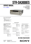
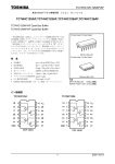
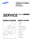
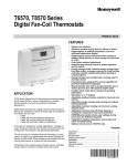
1
SERVICE MANUAL
MODEL
..............
DXF-51
DXF-51
DXF-51
DEST.
.........
CHASSIS NO.
....................
JPN
SMC-340-A
Serial No. 30,001 and higher
US/CND
SMC-341-A
Serial No. 10,001 and higher
AEP
MODEL
..............
DEST.
.........
DXF-51
DXF-51
Serial No. 100,001 and higher
CHASSIS NO.
....................
US/CND/JPN
CE
Serial No. 400,001 and higher
SMC-342-A
Serial No. 40,001 and higher
REVISED-1
ELECTRONIC VIEWFINDER
! WARNING
This manual is intended for qualified service personnel only.
To reduce the risk of electric shock, fire or injury, do not perform any servicing other than that
contained in the operating instructions unless you are qualified to do so. Refer all servicing to
qualified service personnel.
! WARNUNG
Die Anleitung ist nur für qualifiziertes Fachpersonal bestimmt.
Alle Wartungsarbeiten dürfen nur von qualifiziertem Fachpersonal ausgeführt werden. Um die
Gefahr eines elektrischen Schlages, Feuergefahr und Verletzungen zu vermeiden, sind bei
Wartungsarbeiten strikt die Angaben in der Anleitung zu befolgen. Andere als die angegeben
Wartungsarbeiten dürfen nur von Personen ausgeführt werden, die eine spezielle Befähigung
dazu besitzen.
! AVERTISSEMENT
Ce manual est destiné uniquement aux personnes compétentes en charge de l’entretien. Afin
de réduire les risques de décharge électrique, d’incendie ou de blessure n’effectuer que les
réparations indiquées dans le mode d’emploi à moins d’être qualifié pour en effectuer d’autres.
Pour toute réparation faire appel à une personne compétente uniquement.
WARNING!!
ATTENTION!!
AN INSULATED TRANSFORMER SHOULD BE USED DURING
ANY SERVICE TO AVOID POSSIBLE SHOCK HAZARD, BECAUSE OF LIVE CHASSIS.
THE CHASSIS OF THIS RECEIVER IS DIRECTLY CONNECTED
TO THE AC POWER LINE.
AFIN D’ÉVITER TOUT RISQUE D’ÉLECTROCUTION
PROVENANT D’UN CHÂSSIS SOUS TENSION, UN
TRANSFORMATEUR D’ISOLEMENT DOIT ETRE UTILISÉ LORS
DE TOUT DÉPANNAGE.
LE CHÂSSIS DE CE RÉCEPTEUR EST DIRECTEMENT
RACCORDÉ Á L’ALIMENTATION SECTEUR.
SAFETY-RELATED COMPONENT WARNING !!
ATTENTION AUX COMPOSANTS RELATIFS Á LA
SÉCURITÉ!!
COMPONENTS IDENTIFIED BY A ! MARK ON THE SCHEMATIC
DIAGRAMS, EXPLODED VIEWS AND IN THE PARTS LIST ARE
CRITICAL TO SAFE OPERATION. REPLACE THESE COMPONENTS WITH SONY PARTS WHOSE PART NUMBERS APPEAR
AS SHOWN IN THIS MANUAL OR IN SUPPLEMENTS PUBLISHED BY SONY. CIRCUIT ADJUSTMENTS THAT ARE CRITICAL TO SAFE OPERATION ARE IDENTIFIED IN THIS MANUAL.
FOLLOW THESE PROCEDURES WHENEVER CRITICAL COMPONENTS ARE REPLACED OR IMPROPER OPERATION IS
SUSPECTED.
LES COMPOSANTS IDENTIFIÉS PAR UNE MAPQUE ! SUR
LES SCHÉMAS DE PRINCIPE, LES VUES EXPLOSÉES ET LES
LISTES DE PIECES SONT D’UNE IMPORTANCE CRITIQUE
POUR LA SÉCURITÉ DU FONCTIONNEMENT. NE LES
REMPLACER QUE PAR DES COMPOSANTS SONY DONT LE
NUMÉRO DE PIÈCE EST INDIQUÉ DANS LE PRÉSENT
MANUEL OU DANS DES SUPPLÉMENTS PUBLIÉS PAR SONY.
LES RÉGLAGES DE CIRCUIT DONT L’IMPORTANCE EST CRITIQUE POUR LA SÉCURITÉ DU FONCTIONNEMENT SONT
IDENTIFIÉS DANS LE PRÉSENT MANUEL. SUIVRE CES
PROCÉDURES LORS DE CHAQUE REMPLACEMENT DE
COMPOSANTS CRITIQUES, OU LORSQU’UN MAUVAIS
FONCTIONNEMENT EST SUSPECTÉ.
DXF-51
Table of Contents
1. Operating Instructions ........................................................... 1-1 (E)
2. Service Informations
2-1.
2-2.
Board Layout ......................................................................................... 2-1 (E)
Disassembly .......................................................................................... 2-1 (E)
2-2-1. Stand Assy Removal ............................................................ 2-1 (E)
2-2-2. Bezel Assy Removal ............................................................ 2-2 (E)
2-2-3. Back Cover Removal ........................................................... 2-2 (E)
2-2-4. D Board Removal ................................................................. 2-3 (E)
2-2-5. G and P Boards Removal ..................................................... 2-4 (E)
2-2-6. A Board Removal ................................................................. 2-5 (E)
2-2-7. Picture Tube and Q Board Removal .................................... 2-6 (E)
2-2-8
Removal of Anode Cap ........................................................ 2-6 (E)
3. Safety Related Adjustment ................................................. 3-1 (E)
4. Electrical Adjustments
4-1.
4-2.
4-3.
4-4.
4-5.
4-6.
4-7.
4-8.
4-9.
4-10.
4-11.
4-12.
4-13.
4-14.
4-15.
4-16.
4-17.
Preparation ............................................................................................ 4-1 (E)
Switching Power Output (RV501) Adjustment .................................... 4-1 (E)
H.V. (RV302) High Voltage Adjustment ............................................. 4-1 (E)
H-HOLD (RV104) Adjustment ............................................................. 4-1 (E)
V-HOLD (RV103) Adjustment ............................................................. 4-1 (E)
V-DUTY (RV107) Adjustment ............................................................. 4-1 (E)
H-LEN (L302) Adjustment ................................................................... 4-1 (E)
H-SIZE (RV301) Adjustment ............................................................... 4-1 (E)
Heater Voltage Adjustment ................................................................... 4-1 (E)
V-LIN (RV105) Adjustment ................................................................. 4-2 (E)
V-SIZE (RV109) Adjustment ............................................................... 4-2 (E)
16 : 9 V-SIZE (RV108) Adjustment ..................................................... 4-2 (E)
V-SIZE PAL (RV110) Adjustment ....................................................... 4-2 (E)
BRIGHT (RV102) Adjustment ............................................................. 4-2 (E)
FOCUS (RV111) Adjustment ............................................................... 4-2 (E)
Deflecting Yoke Tilt Adjustment .......................................................... 4-2 (E)
Centering Adjustment ........................................................................... 4-2 (E)
5. Semiconductors ................................................................................. 5-1
DXF-51
1 (E)
6. Spare Parts
6-1.
6-2.
6-3.
Notes on Repair Parts .................................................................................. 6-1
Exploded Views .......................................................................................... 6-2
Electrical Parts List ..................................................................................... 6-6
7. Block Diagrams
Overall ......................................................................................................... 7-1
8. Diagrams
8-1.
2 (E)
Schematic Diagrams and Printed Wiring Boards ........................................ 8-2
Schematic Diagrams
A .................................................................................................................. 8-3
H2 (A)/H2 (B) ............................................................................................. 8-3
G .................................................................................................................. 8-7
H1 ................................................................................................................ 8-7
Q .................................................................................................................. 8-7
D .................................................................................................................. 8-9
P ................................................................................................................... 8-9
Printed Wiring Boards
A .................................................................................................................. 8-2
H2 (A)/H2 (B) ............................................................................................. 8-2
G .................................................................................................................. 8-6
H1 ................................................................................................................ 8-6
Q .................................................................................................................. 8-6
D .................................................................................................................. 8-8
P ................................................................................................................... 8-8
DXF-51
DXF-51
3-859-686-03(1)
Electronic Viewfinder
Manual de instrucciones
2
Operating Instructions
Mode d’emploi
Page 18
Manual d’Istruzioni
Página 48
Pagina 58
Page 28
Bedienungsanleitung
Seite 38
© 1997 by Sony Corporation
English
Table of Contents
Model No. DXF-51
Serial No.
WARNING
To prevent fire or shock hazard, do not
expose the unit to rain or moisture.
To avoid electrical shock, do not open the
cabinet. Refer servicing to qualified
personnel only.
This symbol is intended to alert the
user to the presence of important
operating and maintenance (servicing)
instructions in the literature
accompanying the appliance.
For the customers in the U.S.A.
This equipment has been tested and found to comply with
the limits for a Class A digital device, pursuant to Part 15 of
the FCC Rules. These limits are designed to provide
reasonable protection against harmful interference when the
equipment is operated in a commercial environment. This
equipment generates, uses, and can radiate radio frequency
energy and, if not installed and used in accordance with the
instruction manual, may cause harmful interference to radio
communications. Operation of this equipment in a residential
area is likely to cause harmful interference in which case the
user will be required to correct the interference at his own
expense.
You are cautioned that any changes or modifications not
expressly approved in this manual could void your authority
to operate this equipment.
The shielded interface cable recommended in this manual
must be used with this equipment in order to comply with the
limits for a digital device pursuant to Subpart B of Part 15 of
FCC Rules.
Location and Function of Parts and Controls ............. 21
For the customers in Europe
How To Attach and Connect the Unit
to the Camera ........................................................... 23
This product with the CE marking complies with the EMC
Directive (89/336/EEC) issued by the Commission of the
European Community.
Compliance with this directive implies conformity to the
following European standards:
• EN55103-1: Electromagnetic Interference (Emission)
• EN55103-2: Electromagnetic Susceptibility (Immunity)
This product is intended for use in the following
Electromagnetic Environment(s):
E1 (residential), E2 (commercial and light industrial), E3
(urban outdoors) and E4 (controlled EMC environment, ex.
TV studio).
Features ........................................................................... 20
Precautions ...................................................................... 20
How To Attach the Viewfinder Hood ....................... 25
Operation ......................................................................... 26
Panning ...................................................................... 26
Tilting ........................................................................ 26
Specifications ................................................................... 27
19
Reprinted from the
operating instructions
1-1 (E)
18
This symbol is intended to alert the
user to the presence of uninsulated
“dangerous voltage” within the
product’s enclosure that may be of
sufficient magnitude to constitute a risk
of electric shock to persons.
English
Owner’s Record
The model and serial numbers are located at the rear.
Record the serial number in the space provided below. Refer
to these numbers whenever you call upon your Sony dealer
regarding this product.
Section 1
Operating Instructions
DXF-51
1-2 (E)
Features
The DXF-51 is a 5-inch monochrome electronic viewfinder,
designed for use with Sony DXC series CCD color video
cameras.
• High-resolution picture tube with a horizontal resolution of
over 650 TV lines.
• H/V regulator ensures a stable picture under all conditions.
• Automatically responds to EIA standard (525/59.94) and
CCIR standard (625/50) signals.
Location and Function of Parts and Controls
• Controls from a camera for the adjustment of image size
transmitted via 16:9 (V compression) and 4:3 signals.
• Has three tally lamps at the front of the camera, and one
main tally lamp at the back.
• While maintaining balance, camera tilts 40 degrees up and
down, and pans 90 degrees to right and left.
1 TALLY G indicator (green)
2 TALLY R indicator (red)
3 External tally lamp (red)
qf Auxiliary indicator
qd R indicator
Precautions
Operation
• Do not use the unit in a place subject to direct sunlight,
excessive dust, mechanical vibration or shock.
• Do not use the viewfinder outside its operating temperature
range of 0°C to +40°C (32°F to 104°F).
• Should any liquid or solid object fall into the cabinet,
unplug the unit and have it checked by qualified personnel
before operating it any further.
• Allow adequate air circulation to prevent internal heat
build-up.
• Do not expose the unit to extremely high temperatures and
humidity.
4 LOCK screw
5 D-sub 26-pin connector
qs SHUTTER/GAIN indicator
Cleaning
Clean the cabinet, panel and controls with a soft, dry cloth,
or a soft cloth that has been lightly moistened with a mild
detergent solution. Do not use any type of solvent, such as
alcohol or benzine, as this may damage the finish.
Repacking
Do not discard the unit’s original packaging. Use the
packaging to afford maximum protection whenever the unit
is transported.
If you have any questions about your viewfinder, contact
your authorized Sony dealer.
qa PEAKING control
6 CONTRAST control
0 PEAKING ON/OFF switch
7 BRIGHT control
9 TALLY ON/OFF switch
8 Viewfinder fixing ring
1 TALLY G indicator (green)
Lights while the camera is monitoring.
4 LOCK screw
Adjusts the angle of viewfinder in the vertical direction.
2 TALLY R indicator (red)
Lights while the camera is recording.
5 D-sub 26-pin connector
Connects 20-pin connector (supplied) to the VF (viewfinder)
connector of the host camera. This connector carries the
video signal, tally signal and power.
3 External tally lamp (red)
Lights while the camera recording when TALLY switch set
to on.
20
21
Location and Function of Parts and Controls
How To Attach and Connect the Unit to the Camera
6 CONTRAST control 1)
Turn to adjust the contrast of the picture on the viewfinder
screen.
qs SHUTTER/GAIN indicator
Lights while the shutter, the gain control, or the AGC
function is switched on.
7 BRIGHT control 1)
Turn to adjust the brightness of the picture on the viewfinder
screen.
qd R indicator
Lights while the second tally is on in recording.
8 Viewfinder fixing ring
Fix the viewfinder to the camera.
Turn off the power of the camera before attempting the installation.
1
Connect the VF connector cable
(supplied) to the bottom of the
viewfinder.
VF connector cable
Bottom
qf Auxiliary indicator
Signal warning indicator auxiliary lamp (excludes
SHUTTER/GAIN).
9 TALLY ON/OFF switch
Enables and disables the external tally lamps 1 and 2.
ON: The external tally lamp turns on and off, as the
camera mode changes.
OFF: The external tally lamp does not light, regardless of
the camera mode.
0 PEAKING ON/OFF switch
Set this switch to on to use the PEAKING control.
qa PEAKING control 1)
Adjusts the outline intensity of the viewfinder image.
2
Attach the viewfinder to the
accessory shoe of the camera and fix
it.
The viewfinder can also be attached
with its screen facing the subject, if
desired.
Accessory shoe
Stopper
2 Tighten the fixing ring.
1 Slide the
bracket into
the accessory
shoe until it
stops.
---------------------------------------------------------------------------------------------------------------------------------------------------------
DXF-51
1) These controls affect only the viewfinder screen. They have no effect on
the signal being output by the camera.
22
23
DXF-51
How To Attach and Connect the Unit to the Camera
3
How To Attach the Viewfinder Hood
Connect the 20-pin connector to the
camera’s VF connector.
When using the viewfinder outdoors, attach the supplied
viewfinder hood to reduce glare.
Viewfinder hood (supplied)
VF connector cable
(20-piny26-pin)
to VF connector
Fix the hood tightening
screw.
24
25
Operation
Specifications
Turning on the camera or the camera control unit
automatically supplies power to the viewfinder. The
viewfinder image will appear within several seconds.
Picture tube
Note
When the BRIGHT control is turned fully counterclockwise,
no picture will appear on the viewfinder screen.
Adjust the viewfinder to the desired angle and height.
Tilting
Panning
40°
90°
Loosen the LOCK screw
to adjust the angle of
the viewfinder that you
want. After you finished
the adjustment, tighten
the LOCK screw to fix
the angle.
90°
Adjust the controls
to give the best
possible picture.
40°
40°
1-3 (E)
For details, refer to the instruction manual supplied with the
camera or the CCU.
26
5-inch monochrome
70-degree deflection
Video signal EIA standard/CCIR standard
Scanning system
2 : 1 interlace
525 lines
2 : 1 interlace
625 lines
Scan
5 % underscan
High voltage 8.5 kV
Horizontal resolution
More than 650 lines (at center)
Frequency response
10 MHz at –3 dB
Connectors
Exclusive D-sub 26-pin connector
Video input: 1 V(p-p), sync negative,
3 kΩ
Power supply: 12 V DC
Power consumption
11 W
Operating temperature
0°C to +40°C (32°F to 104°F)
Dimensions
Approx. 203 × 199 × 289 mm
(w/h/d) (8 × 7 7/8 × 11 1/2 inches)
including viewfinder hood
Mass
Approx. 2.4 kg (4 lb 7 oz)
including viewfinder hood
Accessories supplied
Viewfinder hood (1)
VF connector cable
(20-piny26-pin) (1)
Number plate (1)
Operating Instructions (1)
Design and specifications are subject to change without
notice.
27
1-4 (E)
Printed in Malaysia
DXF-51
Section 2
Service Informations
2-1. Board Layout
P
G
D
H2 (B)
H2 (A)
A
Q
H1
2-2. Disassembly
2-2-1. Stand Assy Removal
2 Knob (L)
1 Screw
8 Scew
3 Stopper
7 Stopper
6 Knob (R)
4 Screw
9 Stand assembly
5 Screw
DXF-51
2-1 (E)
2-2-2. Bezel Assy Removal
2 CN601
6 Bezel assy
1 Two screws
5 Lug
3 CN201, 602
4 Screw
1 Two screws
2-2-3. Back Cover Removal
1 Two screws
2 Rear cover
1 Two screws
2-2 (E)
DXF-51
2-2-4. D Board Removal
3 Two connectors
(CN302, 305)
4 D board
2 Four screws
1 Three connectors
(CN301, 303, 304)
DXF-51
2-3 (E)
2-2-5. G and P Boards Removal
1 Four screws
3 G board
4 Four screws
6 P board
2 Two connectors
(CN501, 502)
5 Two connectors
(CN401, 402)
2-4 (E)
DXF-51
2-2-6. A Board Removal
n
When the A board is going to be replaced in the monitor that have the serial No. 10001-30000 (UC), 40001-100000 (AEP)
as shown, replace the A board together with the P board at the same time.
1 Two screws
4 Three connectors
(CN101, 106, 108)
3 Lug
8 Two screws
2 Two screws
5 Two connectors
(CN104, 107)
9 board
6 Three connectors
(CN103, 109, 110)
7 Two connectors
(CN102, 105)
8 Two screws
DXF-51
2-5 (E)
2-2-7. Picture Tube and Q Board Removal
4 Two screws
2 Anode cap
3 Picture tube
1 Tow screws
5 Q board
1 Two screws
2-2-8
Removal of Anode Cap
n
Short-circuit the anode of the picture tube and the anode cap to the metal chassis, picture tube shield or carbon painted on
the picture tube, after removing the anode.
. Removal Procedure
c
b
a
b
a
Anode button
(1) Turn up one side of the rubber cap in the
direction indicated by arrow a.
(2) Using a thumb, pull up the rubber cap
firmly in the direction indicated by
arrow b.
. Handling Precautions
(3) When one side of the rubber cap is
separated from the anode button, the
anode-cap can be removed by turning
up the rubber cap and pulling up it in
the direction of the arrow c.
(1) Do not scratch the surface of anode cap with a sharp object.
(2) Do not press the rubber so hard that it damages the inside of
anode caps. A shatter-hook terminal is built into the rubber.
(3) Do not turn the foot of the rubber over.
The shatter-hook terminal will stick out or damage the rubber.
2-6 (E)
DXF-51
Section 3
Safety Related Adjustment
H.V. Regulation Confirmation
This confirmation must be made whenever the following
parts (with marking in circuit diagram) were replaced.
FBT301, R311, R312, R401, RV302
1. Open C304 on the D board.
2. Enter full white signal to pin 6 (VF VIDEO (X)) of
D-sub 26-pin connector (CN702).
3. Connect a high voltage meter to the HV pin of
FBT301 on the P board.
4. Confirm that the voltage is below DC15 kV when both
BRIGHT and CONTRAST are set to the minimum
position.
5. Confirm that the voltage is below DC13.5 kV when
both BRIGHT and CONTRAST are set to the maximum position.
6. Connect the C304 removed in step1.
+B Confirmation
1. Connect a digital voltmeter to the TP302.
2. Confirm that the voltage is DC9.5 ± 0.1 V.
If out of the range, perform the switching power output
adjustment (Section 4).
TP302
C304
D board (Conductor side)
DXF-51
3-1 (E)
Section 4
Electrical Adjustments
4-1. Preparation
4-6. V-DUTY (RV107) Adjustment
Make adjustment under the following conditions, unless
otherwise specified:
. BRIGHT : Mechanical center
. CONTRAST : Marker points “3 o’clock” position
. PEAKING switch : OFF
. Input signal : Enter NTSC monoscope signal to pin 6
of D-sub 26-pin connector (CN702)
1. Enter PAL signal or NTSC signal to pin 6 of a D-sub
26-pin connector (CN702).
2. Connect an oscilloscope to TP114 and observe a
waveform.
3. Adjust RV107 as follows.
NTSC
4-2. Switching Power Output (RV501)
Adjustment
18.35 ±0.5 msec
n
All items of electrical adjustment must be checked, if this
adjustment was made.
PAL
18.35 ±0.5 msec
1. Connect a digital voltmeter to TP103.
2. Rotating RV501, adjust the power to DC9.5 ± 0.1 V.
4-7. H-LEN (L302) Adjustment
4-3. H.V. (RV302) High Voltage
Adjustment
1. Adjust L302 so as to attain the best linearity (horizontal direction) of screen.
n
The H-SIZE, V-SIZE, and Heater Voltage must be
checked, if this adjustment was made.
4-8. H-SIZE (RV301) Adjustment
1. Connect a high voltage meter too the HV pin of
FBT301 on the P board.
2. Adjust RV302 to attain DC8 kV.
n
The Heater voltage must be checked, if this adjustment
was made.
1. Adjust RV301 so that horizontal amplitude of screen
becomes 98 ± 2 mm.
4-4. H-HOLD (RV104) Adjustment
Preparation : No signal input.
1. Connect a frequency counter to TP111.
2. Adjust RV104 to attain 15.734 ± 0.1 kHz.
4-5. V-HOLD (RV103) Adjustment
4-9. Heater Voltage Adjustment
1. Connect a digital voltmeter to TP118.
2. Confirm that the voltage is DC11.7 ± 0.3 V.
3. If exceeding this specification. Break the solder of
JP301 and JP302 in this order.
Preparation : No signal input.
1. Connect a frequency counter to TP112.
2. Adjust RV103 to attain 42 ± 1Hz.
DXF-51
4-1 (E)
4-10. V-LIN (RV105) Adjustment
4-15. FOCUS (RV111) Adjustment
1. Adjust RV105 so as to attain the best linearity (vertical
direction) of screen.
1. Adjust RV111 so as to attain the best focus of screen.
(Specification : Center resolution 650 TV or more)
4-11. V-SIZE (RV109) Adjustment
4-16. Deflecting Yoke Tilt Adjustment
n
The V-SIZE (16 : 9) and V-SIZE (PAL) must be checked,
if this adjustment was made.
n
Do not adjust this, except when CRT is replaced.
1. Adjust RV109 so that vertical amplitude of screen
becomes 73.5 ± 1.5 mm.
4-12. 16 : 9 V-SIZE (RV108) Adjustment
1. Enter 16 : 9 switching signal.
2. Adjust RV108 so that vertical amplitude of screen
becomes 55 ± 1.5 mm.
4-13.
V-SIZE PAL (RV110) Adjustment
1. Enter PAL signal to pin 6 of D-sub 26-pin connector
(CN702).
2. Adjust RV110 so that vertical amplitude of screen
becomes 73 ± 1.5 mm.
1. If an image tilts to the screen, loosen a clamp band
screw and rotate the deflecting yoke to eliminate a tilt.
2. Tighten gently the clamp band screw, and apply
locking paint to the clamp band screw.
Specification : H within ± 0.65d
V within ± 0.92d
4-17. Centering Adjustment
1. Rotating two centering magnets attaching to the
deflecting yoke, adjust so that the image comes to the
center of screen.
Then, apply locking paint to the centering magnets.
Specification : H Difference in frames between left and
right within 0.13 frame.
V Difference in frames between top and
bottom within 0.13 frame.
4-14. BRIGHT (RV102) Adjustment
1. Set both BRIGHT and CONTRAST to “9 o’clock”
position respectively.
2. Adjust RV102 so as to attain the brightness on same
level as black-out.
4-2 (E)
DXF-51
Serial No. 10001 – (UC)
Serial No. 30001 – (J)
Serial No. 40001 – (AEP)
Serial No. 100001 – (UC, J)
Serial No. 400001 – (CE)
RV104 1
1
1
TP111
TP112 TP114
1
RV107
RV110
RV103
1
RV109
RV111
1
RV108
1
1
RV102
TP112
RV104 1
TP114
1 RV107
1
1
1
1
RV109
RV108
RV103 RV110
RV111
1
Component side
1
Conponent side
RV105 TP118
TP111
1
RV102
1
RV105
TP118
TP103
TP103
A board (Conductor side)
A board (Conductor side)
L302
RV302
JP301
JP302
RV301
D board (Conductor side)
D board (Component side)
RV501
G board (Conductor side)
DXF-51
4-3 (E)
IC, Transistor, Diode
Section 5
Semiconductors
BA15218F-E2
TC4W66F(TE12R)
TC7W04F
TC7W08F
TC7W08F(TE12R)
UPC4062G2
UPC842G2-E2
2SB1548
2SD2374
1SS184
MA152WK-TX
LD-001DU
LD-001VR
3
2
1
3
B
C
E
CATHODE
MARK
1
2
2
1
1
2SC3518-ZL-E2
2SC3518L
TOP VIEW
3
2
1
3
DSA3A2
8pin SOP
MA143A-(TX).SO
C
CATHODE
HA11423MP
1
ANODE
18
CATHODE
16
3
NC
B C
7
E
12
8
11
ANODE
2SC4080
RLS245TE-11
CATHODE
TOP VIEW
ERA22-06TP1
ERA22-08
RD2.0SB-T1
M5237ML-TP1
B
CATHODE
C
E
1
ANODE
2SJ246S-TL
2
3
D
ANODE
MC74HC4538AF
TC4538BF
TC74HC595AF(EL)
UPC494GS
UPC494GS-T1
RU3AM
CATHODE
ERC25-04S
ERC81-004
CATHODE
G D
S
ANODE
1
TOP VIEW
2SK2012
ANODE
YG911S2R
16pin SOP
ESJA57-04AT
TC74HC126AF(EL)
1
CATHODE
TOP VIEW
G
14pin DIP
2SA1576A-T106-Q
2SA1576A-T106-R
2SC3722K-R
2SC4081T106R
2SC4178-F14
2SC4178-T1F14
2SD1328-RST-TX
D
S
CATHODE
ANODE
2SK664
2SK664-TX
ANODE
D
G
S
C
B
E
DXF-51
5-1
Section 6
Spare Parts
6-1. Notes on Repair Parts
1. Safety Related Components Warning
w
Components marked ! are critical to safe operation.
Therefore, specified parts should be used in the case of
replacement.
[WARNHINWEIS]
Les composants identifiés par la marque ! sont
critiques pour la sécurité.
Ne les remplacer que par une pièce portant le numéro
spécifié.
2. Standardization of Parts
Some repair parts supplied by Sony differ from those
used for the unit. These are because of parts commonality and improvement.
Parts List has the present standardized repair parts.
3. Stock of Parts
Parts marked with “o” at SP (Supply Code) column of
the Spare Parts list may not be stocked. Therefore, the
delivery date will be delayed.
Items with no part number and no description are not
stocked because they are seldom required for routine
service.
4. Units for Capacitors, Inductors and Resistors
The following units are assumed in Schematic Diagrams, Electrical Parts List and Exploded Views
unless otherwise specified.
Capacitors
: µF
Inductors
: µH
Resistors
:Ω
5. X-ray Radiation Safety Related Parts
The components marked in this Spare Parts List
have been carefully factory-selected for each set in
order to satisfy regulations regarding X-ray radiation.
DXF-51
6-1
Mask & Cover Assemblies
6-2. Exploded Views
2
10
BTP3 x 8
B3 x 14
9
PTP2.6 x 5
B3 x 14
5
12
7
PTP2.6 x 8
B3 x 12
1
PTP
2.6 x 8
11
PTP2.6 x 5
PTP2.6 x 5
B3 x 12
6
8
4
BOLT, HEXAGON
SOCKET 4 x 20
BOLT, HEXAGON
SOCKET 4 x 20
3
PTP2.6 x 5
B3 x 4
6-2
DXF-51
Mask & Cover Assemblies
No.
Part No.
SP Description
1
2
3
4
5
6
X-3705-096-1
3-167-517-01
3-617-628-01
3-701-506-01
3-709-224-01
3-709-225-01
o
s
o
s
s
o
STAND ASSY
PLATE, NUNBER
CRT CUSHION
SET-SCREW HEX M3.4X4(WP)
BEAEL
NAME PLATE, SWITCH
7
8
9
10
3-709-226-01
3-709-227-01
3-709-228-01
3-709-229-01
o
o
o
o
MASK(UPPER), LED
MASK(LOWER), LED
COVER, REAR
COVER, LAMP
11
12
3-709-250-01 o MASK, CRT
9-939-875-02 o MOUNTED CIRCUIT BOARD, H1
Screws/Washers
7-682-545-09
7-682-550-09
7-682-551-09
7-683-425-04
7-685-132-19
s
s
s
s
s
SCREW
SCREW
SCREW
BOLT,
SCREW
+B 3X4
+B 3X12
+B 3X14
HEXAGON SOCKET 4X20
+PTP 2.6X5
7-685-134-19 s SCREW +PTP 2.6X8
7-685-546-14 s SCREW +BTP 3X8
DXF-51
6-3
Chassis & CRT Assemblies
B3 x 6
B3 x 6
B3 x 6
118
117
107
106
B3 x 6
116
B3 x 6
B3 x 6
104
102
B3 x 6
111
101
B3 x 6
B3 x 6
K2 x 6
105
114
B3 x 6
115
103
112
120
121
110
119
N3, Type2
LW3
113
108
B3 x 25
N4, Type2
PWH3 x 8
110
P4 x 12
109
PWH3 x 8
6-4
DXF-51
Chassis & CRT Assemblies
Note
*1 Serial
Serial
Serial
*2 Serial
Serial
No.
No.
No.
No.
No.
10001-(UC)
30001-(J)
40001-(AEP)
100001-(UC, J)
400001-(CE)
When the A board is going to be replaced in the monitor
that have the serial No. *1 as shown, replace the A
board together with the P board at the same time.
No.
Part No.
SP Description
101
102
103
104
105
1-517-075-00
1-518-411-21
1-782-353-11
3-173-323-01
3-709-231-01
s
s
s
s
o
SOCKET, LAMP
LAMP
CABLE B,VF(20P-26P)
CAP, TALLY LAMP
FRAME, BOARD(LOWER)
106
107
108
109
110
111
3-709-232-01
3-709-233-01
3-709-234-01
3-709-235-01
3-709-236-01
3-709-237-01
o
o
o
o
o
o
FRAME, BOARD(UPPER)
FRAME, POWER
BAND, CRT
RING, CRT RETAINING
HOOK
CHASSIS, MAIN
112
3-709-238-01 s
113
4-855-006-11 s
114 *1 9-939-870-02 o
115
9-939-878-02 o
116
9-939-887-02 o
SPRING
SLEEVE,
MOUNTED
MOUNTED
MOUNTED
L14
CIRCUIT BOARD, A
CIRCUIT BOARD, Q
CIRCUIT BOARD, D
117 *1 9-939-889-02 o MOUNTED CIRCUIT BOARD, P (INCLUDING FBT)
118
9-939-894-02 o MOUNTED CIRCUIT BOARD, G
119 ! 9-939-895-01 s CRT (C-5D01B45)
120
9-939-896-01 s CRT SOCKET
121 ! 9-939-897-01 s DY(DDY-B5126)
Screws/Washers
7-621-555-40
7-623-422-07
7-682-154-01
7-682-163-01
7-682-547-04
s
s
s
s
s
SCREW +K 2X6
WASHER, LW3 (TYPE3)
SCREW +B 3X25
SCREW +P 4X12
SCREW +B 3X6
7-682-903-21 s SCREW +PWH 3X8
7-684-023-04 s NUT, M3 TYPE2
7-684-024-04 s NUT, M4 TYPE2
DXF-51
6-5
6-3. Electrical Parts List
------A BOARD
------Note:
*1
Serial
Serial
Serial
*2
Serial
Serial
(A BOARD)
No.
No.
No.
No.
No.
Ref. No.
or Q’ty Part No.
10001- (UC)
30001- (J)
40001- (AEP)
100001- (UC, J)
400001- (CE)
When the A board is going to be replaced in the monitor
that have the serial No. *1 as shown, replace the A
board together with the P board at the same time.
Ref. No.
or Q’ty Part No.
SP Description
1pc
1pc
9-939-870-02 o MOUNTED CIRCUIT BOARD, A
1-533-223-11 s CLIP,FUSE
C101
C102
C103
C104
C105
1-104-919-11
1-104-919-11
1-104-919-11
1-104-823-11
1-104-823-11
s
s
s
s
s
CAPACITOR,TANTALUM
CAPACITOR,TANTALUM
CAPACITOR,TANTALUM
CAPACITOR,TANTALUM
CAPACITOR,TANTALUM
C106
C107
C108
C109
C110
1-163-105-00
1-163-113-00
1-104-919-11
1-164-346-11
1-164-346-11
s
s
s
s
s
CAPACITOR,CHIP CERAMIC 33PF/50
CAPACITOR,CHIP CERAMIC 68PF/50
CAPACITOR,TANTALUM 10MF/25V
CAPACITOR,CHIP CERAMIC 1MF/16V
CAPACITOR,CHIP CERAMIC 1MF/16V
C111
C112
C113
C114
C115
1-163-125-00
1-164-346-11
1-163-117-00
1-163-832-00
1-164-346-11
s
s
s
s
s
CAPACITOR,CERAMIC 220PF/50V SL
CAPACITOR,CHIP CERAMIC 1MF/16V
CAPACITOR,CHIP CERAMIC 100PF
CAPACITOR,CERAMIC 0.1MF/100V
CAPACITOR,CHIP CERAMIC 1MF/16V
C117
C118
C119
C120
C121
9-885-015-33
1-128-578-11
1-104-919-11
1-104-919-11
1-164-004-11
s
s
s
s
s
CAPACITOR,ELECT 1000U/16V
CAPACITOR,ELECT 1MF/100V
CAPACITOR,TANTALUM 10MF/25V
CAPACITOR,TANTALUM 10MF/25V
CAPACITOR,CERAMIC 0.1MF/25V
C122
C123
C124
C125
C126
1-164-346-11
1-164-346-11
1-104-919-11
1-104-823-11
1-164-004-11
s
s
s
s
s
CAPACITOR,CHIP CERAMIC 1MF/16V
CAPACITOR,CHIP CERAMIC 1MF/16V
CAPACITOR,TANTALUM 10MF/25V
CAPACITOR,TANTALUM 47MF/16V
CAPACITOR,CERAMIC 0.1MF/25V
C127
C129
C130
C131
C132
1-164-004-11
1-130-734-00
9-939-858-01
1-164-004-11
1-107-689-21
s
s
s
s
s
CAPACITOR,CERAMIC 0.1MF/25V
CAPACITOR,FILM 0.0068MF/100V
CAPACITOR, ELECT 100UF/16V
CAPACITOR,CERAMIC 0.1MF/25V
CAPACITOR,TANTALUM 1MF/35V
C133
C134
C135
C136
C137
1-130-994-11
1-126-393-11
9-939-858-01
1-137-459-11
1-130-734-00
s
s
s
s
s
CAPACITOR,ELECT 0.033MF/50V PP
CAPACITOR,ELECT 33MF/10V(CHIP)
CAPACITOR, ELECT 100UF/16V
CAPACITOR,FILM 0.0056MF/100V
CAPACITOR,FILM 0.0068MF/100V
C138
C139
C140
C141
C142
1-107-689-21
1-107-689-21
1-163-145-00
1-164-004-11
1-164-004-11
s
s
s
s
s
CAPACITOR,TANTALUM 1MF/35V
CAPACITOR,TANTALUM 1MF/35V
CAPACITOR,CHIP CERAMIC 1500PF
CAPACITOR,CERAMIC 0.1MF/25V
CAPACITOR,CERAMIC 0.1MF/25V
C143
C144
C145
C146
C147
1-163-127-00
1-107-689-21
1-104-919-11
1-104-919-11
1-104-919-11
s
s
s
s
s
CAPACITOR,CHIP CERAMIC 270PF
CAPACITOR,TANTALUM 1MF/35V
CAPACITOR,TANTALUM 10MF/25V
CAPACITOR,TANTALUM 10MF/25V
CAPACITOR,TANTALUM 10MF/25V
6-6
10MF/25V
10MF/25V
10MF/25V
47MF/16V
47MF/16V
SP Description
C148
C149
C150
C151
C152
1-104-919-11
9-939-858-01
9-885-015-33
1-163-127-00
1-104-919-11
s
s
s
s
s
CAPACITOR,TANTALUM 10MF/25V
CAPACITOR, ELECT 100UF/16V
CAPACITOR,ELECT 1000U/16V
CAPACITOR,CHIP CERAMIC 270PF
CAPACITOR,TANTALUM 10MF/25V
C153
C154
C155
C156
C157
1-163-145-00
1-136-165-00
1-163-125-00
1-104-919-11
1-163-117-00
s
s
s
s
s
CAPACITOR,CHIP CERAMIC 1500PF
CAPACITOR,FILM 0.1MF/50V (PP)
CAPACITOR,CERAMIC 220PF/50V SL
CAPACITOR,TANTALUM 10MF/25V
CAPACITOR,CHIP CERAMIC 100PF
C158
C159
C160
1-164-004-11 s CAPACITOR,CERAMIC 0.1MF/25V
1-130-338-11 s 0APACITOR FILM 0.01MF/630V(PP)
1-164-004-11 s CAPACITOR,CERAMIC 0.1MF/25V
CN101
CN102
CN103
CN104
CN105
1-695-904-11
1-564-705-11
1-506-944-11
1-506-611-11
1-564-706-11
o
o
o
o
s
PIN, CONNECTOR (PC BOARD) 20P
PIN,CONNECTOR (3P)
PIN,CONNECTOR 2P
PIN,CONNECTOR 8P
PIN,CONNECTOR (4P)
CN106
CN107
CN108
CN109
CN110
1-580-716-11
1-566-757-11
1-566-763-11
1-564-505-11
1-560-060-00
o
s
o
s
s
PIN, CONNECTOR (PC BOARD) 13P
PIN, CONNECTOR (PC BOARD) 2P
PIN,CONNECTOR (PC BOARD) 8P
PLUG,CONNECTOR (2P)
PIN,CONNECTOR 2P
D101
D103
D104
D105
D106
8-719-068-64
8-719-068-64
8-719-052-18
8-719-052-18
8-719-070-38
s
s
s
s
s
DIODE
DIODE
DIODE
DIODE
DIODE
MA143A-(TX).SO
MA143A-(TX).SO
RLS245TE-11
RLS245TE-11
ESJA57-04AT
D108
D109
D110
D111
D112
8-719-801-78
8-719-068-64
8-719-068-64
8-719-801-78
8-719-052-18
s
s
s
s
s
DIODE
DIODE
DIODE
DIODE
DIODE
1SS184
MA143A-(TX).SO
MA143A-(TX).SO
1SS184
RLS245TE-11
DL101
1-406-729-21 s DELAY LINE,LC (120NS)
F101 ! 1-532-825-11 s FUSE,GLASS 2A/250V (20MM)
IC102
IC103
IC104
IC105
IC106
8-759-366-35
8-759-142-20
8-759-237-79
8-759-242-76
8-759-242-74
s
s
s
s
s
IC
IC
IC
IC
IC
TC4W66F (TE12R)
UPC4062G2
TC74HC595AF (EL)
TC7W08F
TC7W04F
IC107
8-759-235-91 s
IC108
8-759-300-28 s
IC109 *1 8-759-524-55 s
IC109 *2 8-759-038-15 s
IC110
8-759-242-74 s
IC
IC
IC
IC
IC
TC74HC126AF (EL)
HA11423MP
TC4538BF
MC74HC4538AF
TC7W04F
IC111
IC112
IC113
8-759-242-74 s IC TC7W04F
8-759-242-74 s IC TC7W04F
8-759-237-79 s IC TC74HC595AF (EL)
L101
9-939-863-01 s INDUCTOR, CHIP 82UH
Q101
Q102
Q103
Q104
Q105
8-729-905-38
8-729-905-38
8-729-905-38
8-729-036-38
8-729-036-38
s
s
s
s
s
TRANSISTOR
TRANSISTOR
TRANSISTOR
TRANSISTOR
TRANSISTOR
2SC4081T106R
2SC4081T106R
2SC4081T106R
2SC4080
2SC4080
DXF-51
(A BOARD)
(A BOARD)
Ref. No.
or Q’ty Part No.
Ref. No.
or Q’ty Part No.
SP Description
SP Description
Q106
Q107
Q108
Q109
Q110
8-729-117-73
8-729-117-73
8-729-905-38
8-729-905-38
8-729-905-38
s
s
s
s
s
TRANSISTOR
TRANSISTOR
TRANSISTOR
TRANSISTOR
TRANSISTOR
2SC4178-F14
2SC4178-F14
2SC4081T106R
2SC4081T106R
2SC4081T106R
R133
R134
R135
R136
R137
1-216-055-00
1-216-046-00
1-216-079-00
1-216-025-00
1-216-042-00
s
s
s
s
s
RESISTOR,CHIP
RESISTOR,CHIP
RESISTOR,CHIP
RESISTOR,CHIP
RESISTOR,CHIP
1.8K 1/10W(2012)
750 1/10W (2012)
18K 1/10W(2012)
100 1/10W(2012)
510 1/10W (2125)
Q111
Q113
Q115
Q116
Q117
8-729-036-38
8-729-924-97
8-729-905-38
8-729-105-19
8-729-905-38
s
s
s
s
s
TRANSISTOR
TRANSISTOR
TRANSISTOR
TRANSISTOR
TRANSISTOR
2SC4080
2SC3722K-R
2SC4081T106R
2SC3518L
2SC4081T106R
R139
R140
R141
R142
R143
1-216-057-00
1-208-771-11
1-216-046-00
1-216-057-00
1-216-069-11
s
s
s
s
s
RESISTOR,CHIP
RESISTOR,CHIP
RESISTOR,CHIP
RESISTOR,CHIP
RESISTOR,CHIP
2.2K 1/10W(2012)
360 1/10W (2012)
750 1/10W (2012)
2.2K 1/10W(2012)
6.8K 1/10W(2012)
Q118
Q120
Q121
Q122
Q123
8-729-905-38
8-729-905-38
8-729-905-38
8-729-905-38
8-729-905-38
s
s
s
s
s
TRANSISTOR
TRANSISTOR
TRANSISTOR
TRANSISTOR
TRANSISTOR
2SC4081T106R
2SC4081T106R
2SC4081T106R
2SC4081T106R
2SC4081T106R
R144
R145
R146
R147
R148
1-216-089-00
1-216-089-00
1-216-049-11
1-216-065-00
1-216-033-00
s
s
s
s
s
RESISTOR,CHIP
RESISTOR,CHIP
RESISTOR,CHIP
RESISTOR,CHIP
RESISTOR,CHIP
47K 1/10W(2012)
47K 1/10W(2012)
1K 1/10W(2012)
4.7K 1/10W(2012)
220 1/10W(2012)
Q124
Q125
Q126
Q127
Q128
9-939-864-01
9-939-865-01
8-729-420-75
8-729-905-38
8-729-905-38
s
s
s
s
s
TRANSISTOR
TRANSISTOR
TRANSISTOR
TRANSISTOR
TRANSISTOR
2SD2374
2SB1548
2SD1328-RST-TX
2SC4081T106R
2SC4081T106R
R149
R150
R151
R152
R153
1-216-042-00
1-216-065-00
1-216-073-00
1-216-039-00
1-216-055-00
s
s
s
s
s
RESISTOR,CHIP
RESISTOR,CHIP
RESISTOR,CHIP
RESISTOR,CHIP
RESISTOR,CHIP
510 1/10W (2125)
4.7K 1/10W(2012)
10K 1/10W(2012)
390 1/10W(2012)
1.8K 1/10W(2012)
Q129
Q130
Q131
Q132
Q133
8-729-905-38
8-729-905-38
8-729-422-12
8-729-026-52
8-729-026-52
s
s
s
s
s
TRANSISTOR
TRANSISTOR
FET 2SK664
TRANSISTOR
TRANSISTOR
2SC4081T106R
2SC4081T106R
R154
R155
R156
R157
R158
1-216-001-00
1-216-461-00
1-216-061-00
1-216-097-00
1-216-097-00
s
s
s
s
s
RESISTOR,CHIP 10 1/10W(2012)
RESISTOR,METAL FILM 5.6K/2W
RESISTOR,CHIP 3.3K 1/10W(2012)
RESISTOR,CHIP 100K 1/10W(2012)
RESISTOR,CHIP 100K 1/10W(2012)
Q134
Q135
8-729-905-38 s TRANSISTOR 2SC4081T106R
8-729-036-38 s TRANSISTOR 2SC4080
R101
R102
R103
R104
R105
1-216-069-11
1-216-033-00
1-216-073-00
1-216-295-00
1-216-073-00
s
s
s
s
s
RESISTOR,CHIP 6.8K 1/10W(2012)
RESISTOR,CHIP 220 1/10W(2012)
RESISTOR,CHIP 10K 1/10W(2012)
CONDUCTOR CHIP (2012)
RESISTOR,CHIP 10K 1/10W(2012)
R159
R160
R161
R162
R163
1-216-073-00
1-216-077-00
1-216-057-00
1-216-104-00
1-216-356-00
s
s
s
s
s
RESISTOR,CHIP 10K 1/10W(2012)
RESISTOR,CHIP 15K 1/10W(2012)
RESISTOR,CHIP 2.2K 1/10W(2012)
RESISTOR,CHIP 200K 1/10W(2012)
RESISTOR,METAL FILM 3.9/1W
R106
R107
R108
R109
R110
1-216-073-00
1-216-073-00
1-216-049-11
1-216-073-00
1-216-073-00
s
s
s
s
s
RESISTOR,CHIP
RESISTOR,CHIP
RESISTOR,CHIP
RESISTOR,CHIP
RESISTOR,CHIP
10K 1/10W(2012)
10K 1/10W(2012)
1K 1/10W(2012)
10K 1/10W(2012)
10K 1/10W(2012)
R164
R165
R166
R167
R168
1-216-046-00
1-216-073-00
1-216-066-00
1-216-073-00
1-216-089-00
s
s
s
s
s
RESISTOR,CHIP
RESISTOR,CHIP
RESISTOR,CHIP
RESISTOR,CHIP
RESISTOR,CHIP
R113
R114
R115
R116
R117
1-216-073-00
1-216-089-00
1-216-081-00
1-216-085-00
1-216-073-00
s
s
s
s
s
RESISTOR,CHIP
RESISTOR,CHIP
RESISTOR,CHIP
RESISTOR,CHIP
RESISTOR,CHIP
10K
47K
22K
33K
10K
R169
R170
R171
R172
R173
1-249-385-11
1-216-060-00
1-216-073-00
1-216-295-00
1-216-295-00
s
s
s
s
s
RES,CARBON 2.2 1/4W
RESISTOR,CHIP 3K 1/10W (2012)
RESISTOR,CHIP 10K 1/10W(2012)
CONDUCTOR CHIP (2012)
CONDUCTOR CHIP (2012)
R118
R119
R120
R121
R122
1-216-073-00
1-216-073-00
1-247-842-11
1-216-081-00
1-216-081-00
s
s
s
s
s
RESISTOR,CHIP 10K 1/10W(2012)
RESISTOR,CHIP 10K 1/10W(2012)
RESISTOR,CARBON 3K 1/4W
RESISTOR,CHIP 22K 1/10W(2012)
RESISTOR,CHIP 22K 1/10W(2012)
R174
R175
R176
R178
R179
1-216-295-00
1-216-073-00
1-216-073-00
1-216-073-00
1-216-073-00
s
s
s
s
s
CONDUCTOR CHIP (2012)
RESISTOR,CHIP 10K 1/10W(2012)
RESISTOR,CHIP 10K 1/10W(2012)
RESISTOR,CHIP 10K 1/10W(2012)
RESISTOR,CHIP 10K 1/10W(2012)
R123
R124
R125
R126
R127
1-216-057-00
1-216-033-00
1-216-039-00
1-216-081-00
1-216-081-00
s
s
s
s
s
RESISTOR,CHIP
RESISTOR,CHIP
RESISTOR,CHIP
RESISTOR,CHIP
RESISTOR,CHIP
2.2K 1/10W(2012)
220 1/10W(2012)
390 1/10W(2012)
22K 1/10W(2012)
22K 1/10W(2012)
R180
R181
R182
R184
R185
1-216-073-00
1-216-046-00
1-216-046-00
1-216-046-00
1-216-046-00
s
s
s
s
s
RESISTOR,CHIP
RESISTOR,CHIP
RESISTOR,CHIP
RESISTOR,CHIP
RESISTOR,CHIP
R128
R129
R130
R131
R132
1-216-025-00
1-216-061-00
1-216-042-00
1-216-042-00
1-216-040-00
s
s
s
s
s
RESISTOR,CHIP
RESISTOR,CHIP
RESISTOR,CHIP
RESISTOR,CHIP
RESISTOR,CHIP
100 1/10W(2012)
3.3K 1/10W(2012)
510 1/10W (2125)
510 1/10W (2125)
430 1/10W (2012)
R186
R187
R188
R189
R190
1-216-046-00
1-216-295-00
1-216-295-00
1-215-863-11
1-216-025-00
s
s
s
s
s
RESISTOR,CHIP 750 1/10W (2012)
CONDUCTOR CHIP (2012)
CONDUCTOR CHIP (2012)
RESISTOR,METAL 100/1W
RESISTOR,CHIP 100 1/10W(2012)
R191
R192
R193
R194
1-216-075-00
1-216-462-00
1-216-073-00
1-216-075-00
s
s
s
s
RESISTOR,CHIP 12K 1/10W(2012)
RESISTOR,METAL FILM 8.2K/2W
RESISTOR,CHIP 10K 1/10W(2012)
RESISTOR,CHIP 12K 1/10W(2012)
DXF-51
2SA1576A-T106-R
2SA1576A-T106-R
1/10W(2012)
1/10W(2012)
1/10W(2012)
1/10W(2012)
1/10W(2012)
750 1/10W (2012)
10K 1/10W(2012)
5.1K 1/10W(2012)
10K 1/10W(2012)
47K 1/10W(2012)
10K
750
750
750
750
1/10W(2012)
1/10W (2012)
1/10W (2012)
1/10W (2012)
1/10W (2012)
6-7
(A BOARD)
(A BOARD)
Ref. No.
or Q’ty Part No.
Ref. No.
or Q’ty Part No.
SP Description
SP Description
R195
R196
R197
R198
R199
1-216-046-00
1-216-049-11
1-216-060-00
1-216-060-00
1-216-049-11
s
s
s
s
s
RESISTOR,CHIP
RESISTOR,CHIP
RESISTOR,CHIP
RESISTOR,CHIP
RESISTOR,CHIP
750 1/10W (2012)
1K 1/10W(2012)
3K 1/10W (2012)
3K 1/10W (2012)
1K 1/10W(2012)
R254
R255
R256
R258
R260
1-216-121-00
1-216-610-11
1-216-031-00
1-216-295-00
1-215-869-11
s
s
s
s
s
RESISTOR,CHIP 1M 1/10W(2012)
RESISTOR,CHIP 20 1/10W(2012)
RESISTOR,CHIP 180 1/10W(2012)
CONDUCTOR CHIP (2012)
RESISTOR,METAL FILM 1K/1W
R200
R201
R202
R203
R204
1-216-049-11
1-216-049-11
1-216-073-00
1-216-049-11
1-216-049-11
s
s
s
s
s
RESISTOR,CHIP
RESISTOR,CHIP
RESISTOR,CHIP
RESISTOR,CHIP
RESISTOR,CHIP
1K 1/10W(2012)
1K 1/10W(2012)
10K 1/10W(2012)
1K 1/10W(2012)
1K 1/10W(2012)
R261
R264
R265
R266
1-216-133-00
1-216-073-00
1-216-049-11
1-216-047-00
s
s
s
s
RESISTOR,CHIP
RESISTOR,CHIP
RESISTOR,CHIP
RESISTOR,CHIP
R205
R206
R208
R209
R210
1-216-073-00
1-216-081-00
1-216-295-00
1-216-061-00
1-216-071-00
s
s
s
s
s
RESISTOR,CHIP 10K 1/10W(2012)
RESISTOR,CHIP 22K 1/10W(2012)
CONDUCTOR CHIP (2012)
RESISTOR,CHIP 3.3K 1/10W(2012)
RESISTOR,CHIP 8.2K 1/10W(2012)
R211
R212
R213
R214
R215
1-216-003-11
1-216-066-00
1-216-065-00
1-216-093-11
1-216-689-11
s
s
s
s
s
RESISTOR,CHIP
RESISTOR,CHIP
RESISTOR,CHIP
RESISTOR,CHIP
RESISTOR,CHIP
12 1/10W(2012)
5.1K 1/10W(2012)
4.7K 1/10W(2012)
68K
39K 1/10W(2012)
R216
R217
R218
R219
R220
1-216-074-00
1-216-082-00
1-216-070-00
1-216-027-00
1-216-073-00
s
s
s
s
s
RESISTOR,CHIP
RESISTOR,CHIP
RESISTOR,CHIP
RESISTOR,CHIP
RESISTOR,CHIP
11K 1/10W(2012)
24K 1/10W(2012)
7.5K 1/10W(2012)
120 1/10W(2012)
10K 1/10W(2012)
R221
R222
R223
R224
R225
1-216-041-11
1-216-093-11
1-216-021-00
1-216-107-00
1-216-089-00
s
s
s
s
s
RESISTOR,CHIP
RESISTOR,CHIP
RESISTOR,CHIP
RESISTOR,CHIP
RESISTOR,CHIP
470 1/10W (2012)
68K
68 1/10W(2012)
270K 1/10W(2012)
47K 1/10W(2012)
R226
R227
R228
R229
R230
1-216-089-00
1-216-073-00
1-216-035-00
1-216-035-00
1-216-025-00
s
s
s
s
s
RESISTOR,CHIP
RESISTOR,CHIP
RESISTOR,CHIP
RESISTOR,CHIP
RESISTOR,CHIP
47K
10K
270
270
100
R231
R232
R233
R234
R235
1-216-061-00
1-216-025-00
1-216-356-00
1-216-037-00
1-216-077-00
s
s
s
s
s
RESISTOR,CHIP 3.3K 1/10W(2012)
RESISTOR,CHIP 100 1/10W(2012)
RESISTOR,METAL FILM 3.9/1W
RESISTOR,CHIP 330 1/10W(2012)
RESISTOR,CHIP 15K 1/10W(2012)
R236
1-216-077-00 s
R237
1-216-073-00 s
R238 *1 1-216-085-00 s
R238 *2 1-216-689-11 s
R239 *1 1-216-101-00 s
RESISTOR,CHIP
RESISTOR,CHIP
RESISTOR,CHIP
RESISTOR,CHIP
RESISTOR,CHIP
1/10W(2012)
1/10W(2012)
1/10W(2012)
1/10W(2012)
1/10W(2012)
3.3M 1/10W(2012)
10K 1/10W(2012)
1K 1/10W(2012)
820 1/10W(2012)
RV102
RV102
RV103
RV103
RV104
*1
*2
*1
*2
*1
1-225-796-11
1-237-039-11
1-225-791-11
1-237-035-11
1-225-789-11
s
s
s
s
s
RESISTOR,ADJ,CERMET
RESISTOR,ADJ,CERMET
RESISTOR,ADJ,CERMET
RESISTOR,ADJ,CERMET
RESISTOR,ADJ,CERMET
100K
100K
5K
5K
2K
RV104
RV105
RV105
RV107
RV107
*2
*1
*2
*1
*2
1-237-034-11
1-225-787-11
1-237-032-11
1-225-796-11
1-237-039-11
s
s
s
s
s
RESISTOR,ADJ,CERMET
RESISTOR,ADJ,CERMET
RESISTOR,ADJ,CERMET
RESISTOR,ADJ,CERMET
RESISTOR,ADJ,CERMET
2K
500
500
100K
100K
RV108
RV108
RV109
RV109
RV110
*1
*2
*1
*2
*1
1-225-787-11
1-237-032-11
1-225-787-11
1-237-032-11
1-225-797-11
s
s
s
s
s
RESISTOR,ADJ,CERMET
RESISTOR,ADJ,CERMET
RESISTOR,ADJ,CERMET
RESISTOR,ADJ,CERMET
RESISTOR,ADJ,CERMET
500
500
500
500
200K
RV110 *2 1-237-040-11 s RESISTOR,ADJ,CERMET 200K
RV111 *1 9-939-789-01 s RESISTOR,ADJ, 1M
RV111 *2 1-237-524-21 s RESISTOR,ADJ,CERMET 1M
SG101
SG102
TP103
TP111
TP112
TP114
TP118
1-519-422-11 s GAP,SPARK
1-519-422-11 s GAP,SPARK
*2
*2
*2
*2
*2
1-535-757-11
1-535-757-11
1-535-757-11
1-535-757-11
1-535-757-11
s
s
s
s
s
CHIP,CHECKER
CHIP,CHECKER
CHIP,CHECKER
CHIP,CHECKER
CHIP,CHECKER
(CONNECTOR)
(CONNECTOR)
(CONNECTOR)
(CONNECTOR)
(CONNECTOR)
15K 1/10W(2012)
10K 1/10W(2012)
33K 1/10W(2012)
39K 1/10W(2012)
150K 1/10W(2012)
R239 *2 1-216-104-00 s RESISTOR,CHIP 200K 1/10W(2012)
R240
1-216-025-00 s RESISTOR,CHIP 100 1/10W(2012)
R241
1-216-025-00 s RESISTOR,CHIP 100 1/10W(2012)
R242
1-216-081-00 s RESISTOR,CHIP 22K 1/10W(2012)
R243
1-216-142-00 s RESISTOR,CHIP 4.7 1/8W(3216)
R244
R245
R246
R247
R248
1-216-142-00
1-216-097-00
1-216-089-00
1-216-093-11
1-216-061-00
s
s
s
s
s
RESISTOR,CHIP
RESISTOR,CHIP
RESISTOR,CHIP
RESISTOR,CHIP
RESISTOR,CHIP
4.7 1/8W(3216)
100K 1/10W(2012)
47K 1/10W(2012)
68K
3.3K 1/10W(2012)
R249
R250
R251
R252
R253
1-216-083-00
1-216-073-00
1-216-073-00
1-216-035-00
1-216-104-00
s
s
s
s
s
RESISTOR,CHIP
RESISTOR,CHIP
RESISTOR,CHIP
RESISTOR,CHIP
RESISTOR,CHIP
27K 1/10W(2012)
10K 1/10W(2012)
10K 1/10W(2012)
270 1/10W(2012)
200K 1/10W(2012)
6-8
DXF-51
------D BOARD
------Note:
*1
Serial
Serial
Serial
*2
Serial
Serial
(D BOARD)
No.
No.
No.
No.
No.
Ref. No.
or Q’ty Part No.
10001- (UC)
30001- (J)
40001- (AEP)
100001- (UC, J)
400001- (CE)
Ref. No.
or Q’ty Part No.
R311
R312
R313
R314
R315
9-939-887-02 o MOUNTED CIRCUIT BOARD, D
C301
C302
C303
C304
C305
1-107-686-11
1-164-004-11
1-164-004-11
1-130-202-00
1-104-913-11
s
s
s
s
s
CAPACITOR,TANTALUM 4.7MF/16V
CAPACITOR,CERAMIC 0.1MF/25V
CAPACITOR,CERAMIC 0.1MF/25V
CAPACITOR,FILM 0.022MF/400V PP
CAPACITOR,TANTALUM 10MF/16V
C306
C307
C308
C309
C311
1-130-202-00 s CAPACITOR,FILM 0.022MF/400V PP
1-104-666-11 s CAPACITOR,ELECT 220MF/25V
9-885-015-34 s CAPACITOR,ELECT 47MF/100V
1-126-941-11 s CAPACITOR,ELECT 470MF/25V
! 1-163-145-00 s CAPACITOR,CHIP CERAMIC 1500PF
C312
C313
C314
C315
C316
! 1-164-004-11 s CAPACITOR,CERAMIC 0.1MF/25V
1-164-004-11 s CAPACITOR,CERAMIC 0.1MF/25V
1-164-346-11 s CAPACITOR,CHIP CERAMIC 1MF/16V
1-164-004-11 s CAPACITOR,CERAMIC 0.1MF/25V
1-104-913-11 s CAPACITOR,TANTALUM 10MF/16V
C317
C318
9-939-783-01 s CAPACITOR,ELECT 6.8MF/50V
1-164-346-11 s CAPACITOR,CHIP CERAMIC 1MF/16V
CN301
CN302
CN303
CN304
CN305
1-564-704-11
1-564-708-11
1-564-506-11
1-564-706-11
1-506-945-11
o
o
o
s
o
PIN,CONNECTOR (2P)
PIN,CONNECTOR (6P)
PLUG,CONNECTOR (3P)
PIN,CONNECTOR (4P)
PIN,CONNECTOR 3P
D301
D302
D303
D304
D305
8-719-068-64
8-719-068-64
8-719-074-79
8-719-948-45
8-719-036-65
s
s
s
s
s
DIODE
DIODE
DIODE
DIODE
DIODE
D306
8-719-068-64 s DIODE MA143A-(TX).SO
IC301
IC302
8-759-095-59 s IC M5237ML-TP1
8-759-824-98 s IC BA15218F-E2
*1
*2
*1
*2
R316
R317
R318
R319
R320
1-216-065-00
1-216-049-11
1-216-295-00
1-216-297-11
1-216-295-00
s
s
s
s
s
RESISTOR,CHIP 4.7K 1/10W(2012)
RESISTOR,CHIP 1K 1/10W(2012)
CONDUCTOR CHIP (2012)
RESISTOR,CHIP 5.1
CONDUCTOR CHIP (2012)
RV301 *1 1-225-789-11
RV301 *2 1-237-034-11
RV302 *1! 1-225-791-11
RV302 *2! 1-237-035-11
s
s
s
s
RESISTOR ADJ 2K (CERMET)
RESISTOR,ADJ,CERMET 2K
RESISTOR,VARIABLE CHIP 5K
RESISTOR,ADJ,CERMET 5K
MA143A-(TX).SO
MA143A-(TX).SO
YG911S2R
ERA22-08
RD2.0SB-T1
9-939-883-01
9-885-015-36
9-939-884-01
9-885-015-38
s
s
s
s
COIL, INDUCTOR 250uH
COIL, INDUCTOR 250uH
COIL (HLC)
HLC VF-60
Q301
Q303
Q305
Q306
9-939-809-01
9-939-806-01
8-729-905-38
8-729-026-52
s
s
s
s
TRANSISTOR
TRANSISTOR
TRANSISTOR
TRANSISTOR
R301
R302
R303
R304
R305
1-216-025-00
1-216-073-00
1-216-298-00
1-216-065-00
1-216-065-00
s
s
s
s
s
RESISTOR,CHIP
RESISTOR,CHIP
RESISTOR,CHIP
RESISTOR,CHIP
RESISTOR,CHIP
100 1/10W(2012)
10K 1/10W(2012)
2.2 1/10(2012)
4.7K 1/10W(2012)
4.7K 1/10W(2012)
R306
R307
R308
R309
R310
1-216-297-11
1-216-070-00
1-216-025-00
1-216-121-00
1-216-121-00
s
s
s
s
s
RESISTOR,CHIP
RESISTOR,CHIP
RESISTOR,CHIP
RESISTOR,CHIP
RESISTOR,CHIP
5.1
7.5K 1/10W(2012)
100 1/10W(2012)
1M 1/10W(2012)
1M 1/10W(2012)
DXF-51
! 1-216-068-00 s RESISTOR,CHIP 6.2K 1/10W(2012)
! 1-216-077-00 s RESISTOR,CHIP 15K 1/10W(2012)
1-216-049-11 s RESISTOR,CHIP 1K 1/10W(2012)
1-216-033-00 s RESISTOR,CHIP 220 1/10W(2012)
1-216-084-00 s RESISTOR,CHIP 30K 1/10W(2012)
SP Description
1pc
L301
L301
L302
L302
SP Description
2SK2012
2SB1548
2SC4081T106R
2SA1576A-T106-R
6-9
------G BOARD
-------
-------H1 BOARD
--------
Ref. No.
or Q’ty Part No.
Ref. No.
or Q’ty Part No.
SP Description
SP Description
1pc
9-939-894-02 o MOUNTED CIRCUIT BOARD, G
1pc
9-939-875-02 o MOUNTED CIRCUIT BOARD, H1
C501
C502
C503
C504
C505
1-104-666-11
1-104-666-11
1-164-004-11
1-163-275-11
1-164-004-11
s
s
s
s
s
CAPACITOR,ELECT 220MF/25V
CAPACITOR,ELECT 220MF/25V
CAPACITOR,CERAMIC 0.1MF/25V
CAPACITOR,CERAMIC 1000PF/50V
CAPACITOR,CERAMIC 0.1MF/25V
CN201
1-580-716-11 s PIN, CONNECTOR (PC BOARD) 13P
RV201
RV202
RV203
9-939-873-01 s RESISTOR, VARIABLE 50K
9-939-871-01 s RESISTOR, VARIABLE 2K
9-939-872-01 s RESISTOR, VARIABLE 5K
C506
C507 *1
C507 *2
C508
C509
1-163-117-00
9-980-048-01
9-885-015-35
1-104-666-11
1-104-666-11
s
s
s
s
s
CAPACITOR,CHIP CERAMIC 100PF
CAPACITOR,ELECT 820MF/25V
CAPACITOR,ELECT 820MF/25V
CAPACITOR,ELECT 220MF/25V
CAPACITOR,ELECT 220MF/25V
SW201
SW202
9-939-874-01 s SWITCH (PEAKING SW)
9-939-874-01 s SWITCH (TALLY SW)
C510
C511
1-164-004-11 s CAPACITOR,CERAMIC 0.1MF/25V
1-104-823-11 s CAPACITOR,TANTALUM 47MF/16V
CN501
CN502
1-564-719-11 s PIN,CONNECTOR (3P)
1-564-718-11 s PIN,CONNECTOR (2P)
D501
D502
9-980-049-01 s DIODE DSA3A2
8-719-981-00 s DIODE ERC81-004
IC501
8-759-144-88 s IC UPC494GS
L501
L502
L503
L504
9-885-015-37
9-939-839-01
9-885-015-37
9-885-015-37
Q501
Q502
Q503
8-729-905-38 s TRANSISTOR 2SC4081T106R
8-729-026-51 s TRANSISTOR 2SA1576A-T106-Q
8-729-023-70 s TRANSISTOR 2SJ246S-TL
R501
R502
R503
R504
R505
1-216-679-11
1-216-079-00
1-216-001-00
1-216-017-00
1-216-679-11
s
s
s
s
s
RESISTOR,CHIP
RESISTOR,CHIP
RESISTOR,CHIP
RESISTOR,CHIP
RESISTOR,CHIP
15K 1/10W(2012)
18K 1/10W(2012)
10 1/10W(2012)
47 1/10W(2012)
15K 1/10W(2012)
R506
R507
R508
R509
R510
1-216-672-11
1-216-672-11
1-216-661-11
1-216-101-00
1-216-073-00
s
s
s
s
s
RESISTOR,CHIP
RESISTOR,CHIP
RESISTOR,CHIP
RESISTOR,CHIP
RESISTOR,CHIP
7.5K 1/10W(2012)
7.5K 1/10W(2012)
2.7K 1/10W(2012)
150K 1/10W(2012)
10K 1/10W(2012)
s
s
s
s
COIL,
COIL,
COIL,
COIL,
INDUCTOR
INDUCTOR
INDUCTOR
INDUCTOR
22uH
65uH
22uH
22uH
RV501 *1 1-225-789-11 s RESISTOR,ADJ,CERMET 500
RV501 *2 1-237-032-11 s RESISTOR,ADJ,CERMET 500
--------H2A BOARD
--------Ref. No.
or Q’ty Part No.
CN601
1-566-760-11 s PIN,CONNECTOR (PC BOARD) 5P
D601
D602
D603
8-719-950-78 s LED LD-001DU
8-719-946-55 s LED LD-001VR
8-719-950-78 s LED LD-001DU
--------H2B BOARD
--------Ref. No.
or Q’ty Part No.
SP Description
CN602
1-566-759-11 s PIN,CONNECTOR 4P
D605
D606
8-719-946-55 s LED LD-001VR
8-719-032-46 s DIODE LD-001MGLM
------P BOARD
------Ref. No.
or Q’ty Part No.
SP Description
1pc
9-939-889-02 o MOUNTED CIRCUIT BOARD, P
(INCLUDED FLYBACK TRANS FBT301)
CN401
CN402
1-564-708-11 o PIN,CONNECTOR (6P)
1-506-944-11 o PIN,CONNECTOR 2P
D401
8-719-300-33 s DIODE RU3AM
R401
6-10
SP Description
! 1-247-887-00 s RESISTOR,CARBON 220K 1/4W
DXF-51
------Q BOARD
------Ref. No.
or Q’ty Part No.
SP Description
1pc
9-939-878-02 o MOUNTED CIRCUIT BOARD, Q
CN701
CN702
1-695-904-11 s PIN, CONNECTOR (PC BOARD) 20P
9-939-877-01 s CONNECTOR TX20A
----------ACCESSORIES
----------Ref. No.
or Q’ty Part No.
SP
1-782-352-11 s
1-782-353-11 s
3-167-517-01 s
3-167-525-02 o
3-859-686-01 s
4-058-477-01
4-058-478-01
4-058-481-01
X-3705-096-1
DXF-51
o
o
o
o
Description
CABLE B, VF (20P-26P)
CABLE A, VF (8P-26P)
PLATE, NUMBER
HOOD, VF
MANUAL, INSTRUCTION (JAPANESE,
ITALIAN, CHINESE)
INDIVIDUAL CARTON
CUSHON (UPPER) ASSY
CUSHON, LOWER
STAND ASSY
6-11
Overall
Overall
Section 7
Block Diagrams
DXF-51
7-1
7-1
Section 8
Diagrams
Note:
. Parts marked “ * ” differ according to the model/destination. Refer
to the mount table for each function.
. All capacitors are in µF unless otherwise noted. pF: µµF 50WV or
less are not indicated except for electrolytics.
. All electrolytics are in 50 V unless otherwise specified.
.
: fusible resistor
.
: nonflammable resistor
.
∆
: internal component
.
: panel designation and adjustment for repair
. Caution when replacing chip parts
New parts must be attached after removal of the chip.
Be careful not to heat the minus side of a tantalum capacitor,
because it is easily damaged by the heat.
Reference information
RESISTOR
RN
RC
FPRD
FUSE
RS
RB
RW
: METAL FILM
: SOLID
: NONFLAMMABLE CARBON
: NONFLAMMABLE FUSIBLE
: NONFLAMMABLE METAL OXIDE
: NONFLAMMABLE CEMENT
: NONFLAMMABLE WIREWOUND
: ADJUSTMENT RESISTOR
COIL
LF-8L
: MICRO INDUCTOR
CAPACITOR
TA
PS
PP
PT
MPS
MPP
ALB
ALT
ALR
: TANTALUM
: STYROL
: POLYPROPYLENE
: MYLAR
: METALIZED POLYESTER
: METALIZED POLYPROPYLENE
: BIPOLAR
: HIGH TEMPERATURE
: HIGH RIPPLE
[Measuring conditions, voltage and waveform]
. A voltage value is the reference value between the measurement
point and the earth, when the color bar signal is received from the
color bar generator. (digital multi-meter used: 10 M ohms/V DC)
. Unit of voltage is V (volt).
(Voltage variations may occur due to normal production tolerances.)
.
: B line
. No mark : Color bar signal.
. Circled numbers indicate the reference waveform.
.
: Signal path.
The components identified marked ! are
critical for safety.
Replace only with the part number specified.
Les composants identifiés par la marque !
sont critiques pour la sécurité.
Ne les remplacer que par une pièce portant
le numéro spécifié.
• The components marked
in this schematic diagram have been
carefully factory-selected for each set in order to satisfy regulations
regarding X-ray radiation.
• When replacing components marked , make the necessary adjustments indicated. If results do not meet the specified value,
change the component marked
and repeat the adjustment until
the specified value is achieved.
• When replacing a part shown in the table below, be sure to perform
the related adjustment.
DXF-51
8-1
8-1
A, H2 (A)/H2 (B)
8-1.
A, H2 (A)/H2 (B)
Schematic Diagrams and Printed Wiring Boards
H2 (A)/H2 (B) -Component side-
Serial No. 100001–(UC, J)
Serial No. 400001–(CE)
H2 (A)/H2 (B) -Conductor side-
A -Component side-
A -Conductor side-
A BOARD
* : Conductor side
D101
D103
D104
D105
D106
D108
D109
D110
D111
D112
*
*
*
*
I-3
G-4
E-5
E-6
A-9
M-8
* J-8
D-8
* H-7
* C-4
IC110
IC111
IC112
IC113
H-9
* M-3
M-7
M-4
*
*
*
*
*
*
IC102
IC103
IC104
IC105
IC106
IC107
IC108
IC109
G-7
J-7
* M-4
M-9
M-7
* M-6
I-8
G-8
Q101
Q102
Q103
Q104
Q105
Q106
Q107
Q108
Q109
Q110
Q111
Q113
Q115
Q116
*
*
*
*
I-2
I-5
H-2
E-5
D-4
G-4
F-6
G-4
G-5
H-5
F-5
L-8
M-2
M-10
Q117
Q118
Q120
Q121
Q122
Q123
Q124
Q124
Q125
Q125
Q126
Q127
Q128
Q129
Q130
Q131
Q132
Q133
Q134
*
*
*
*
*
*
*
*
*
*
*
*
*
*
*
*
L-9
M-9
M-8
M-8
M-8
H-7
C-7
C-7
E-7
E-7
F-7
F-7
F-7
E-7
E-7
C-7
L-5
K-5
K-3
Q135
* E-5
RV102
RV103
RV104
RV105
RV107
RV108
RV109
RV110
RV111
*
*
*
*
*
*
*
*
F-6
I-7
H-9
D-6
F-8
D-7
C-9
G-7
A-8
TP101
TP102
TP103
TP104
TP105
TP106
TP107
*
*
*
*
*
*
*
C-4
F-3
F-3
L-7
J-4
H-2
L-3
TP108
TP109
TP110
TP111
TP112
TP113
TP114
TP115
TP116
TP117
TP118
TP119
*
*
*
*
*
*
*
*
*
*
*
*
C-4
C-7
I-6
B-9
G-9
H-9
G-9
G-9
F-7
G-3
B-4
D-9
8-2 (b)
8-2 (b)
DXF-51
A, H2 (A)/H2 (B)
A, H2 (A)/H2 (B)
Serial No. 10001–(UC)
Serial No. 30001–(J)
Serial No. 40001–(AEP)
H2 (A)/H2 (B) -Component side1
H2 (A)/H2 (B) -Conductor side-
2
3
4
A -Component side-
A -Conductor side-
A BOARD
* : Conductor side
5
D101
D103
D104
D105
D106
D108
D109
D110
D111
D112
*
*
*
*
I-3
G-4
E-5
E-6
A-9
M-8
* J-8
D-8
* H-7
* C-4
IC110
IC111
IC112
IC113
H-9
* M-3
M-7
M-4
*
*
*
*
*
*
IC102
IC103
IC104
IC105
IC106
IC107
IC108
IC109
G-7
J-7
* M-4
M-9
M-7
* M-6
I-8
G-8
Q101
Q102
Q103
Q104
Q105
Q106
Q107
Q108
Q109
Q110
Q111
Q113
Q115
Q116
*
*
*
*
I-2
I-5
H-2
E-5
D-4
G-4
F-6
G-4
G-5
H-5
F-5
L-8
M-2
M-10
Q117
Q118
Q120
Q121
Q122
Q123
Q124
Q124
Q125
Q125
Q126
Q127
Q128
Q129
Q130
Q131
Q132
Q133
Q134
*
*
*
*
*
*
*
*
*
*
*
*
*
*
*
*
L-9
M-9
M-8
M-8
M-8
H-7
C-7
C-7
E-7
E-7
F-7
F-7
F-7
E-7
E-7
C-7
L-5
K-5
K-3
Q135
* E-5
RV102
RV103
RV104
RV105
RV107
RV108
RV109
RV110
RV111
*
*
*
*
*
*
*
*
F-6
I-7
H-9
D-6
F-8
D-7
C-9
G-7
A-8
TP101
TP102
TP103
TP104
TP105
TP106
TP107
*
*
*
*
*
*
*
C-4
F-3
F-3
L-7
J-4
H-2
L-3
TP108
TP109
TP110
TP111
TP112
TP113
TP114
TP115
TP116
TP117
TP118
TP119
*
*
*
*
*
*
*
*
*
*
*
*
C-4
C-7
I-6
B-9
G-9
H-9
G-9
G-9
F-7
G-3
B-4
D-9
8-2 (a)
A
B
C
D
8-2 (a)
DXF-51
E
F
G
H
A, H2 (A)/H2 (B)
CN102
3P
TP103
R258
0
12V
2
E
3
9.5V
5V
9.5V
5.6
C153
1500p
C150
1000
16V
CN109
2P
2
0
V.SIZE
R256
180
RV109
500
1
R210
8.2k
S
2
3
4
5
C129
6800p
R249
27k
RV105
500
3.4
1
5
6
7
8
4
5.2
TC74HC126AF(EL)
C140
1500p
0.7
8.0
22k
R241
100
R240
100
C104
47
16V
VIDEO
R124
220
3.0
R128
100
R126
27k
C105
47
16V
R131
510
R188
0
1
2
3
4
5
R127
22k
6
IC110
TC7W04F
C155
220p
Q133
2SA1576A
PEAK SW
0
7
L101
82µ
R180
10k
9.5V
R246
47k
TP115
R251 Q130
10k 2SC4081
TP116
2.5
C156
10
16
R247 0
68k
BUF3
Q129
2SC4081
BUF2
R192
D104
Q111 8.2k 77.0 RLS245TE-11
2SC4080 2W
PROTEKTOR
R189
VIDEO OUT
Q104
100
1W
36.0
2SC4080
4.2
VIDEO BUF
R155
R154
5.6k
2W 38.0
C114
0.01
100V
R250 0.7
10k
C124 3.6
10
16V
R248
D111
3.3k
MA152WK-TX
STOPER
Q127
2SC4081
BUF4
R253
200k
12
5
0.7
R237
10k RV110
200k
2
25.5
C113
100p
Q109
2SC4081
PEAK AMP2
R139
2.2k
3.8
VIDEO
4
1
HEATER
2
70V
3
FBP2
D103
MA143A-(TX).SO
R134
750
C109
R144
47k
C110
1µ
8.0
R261
3.3M
4
HD2
R157
100k
C115
1
R142
2.2k
R165
10k
R151
10k
5
6
R137
510
R136
100
C107
68p
R172
0
9.5V
Q113
2SC3722K-R
BRT SHIFT
R141
750
R160
15k
R140
360
5
R145
47k
R161
2.2k
6
7
3.1
R153
1.8k
R159
10k
FOCUS
1
GND
2
GND
2
BRIGHT
3
GND
4
HEATER
R238 33K -> 39K
SERIAL NO.
100001-(UC,J)
400001-(AEP)
5
NC
6
400V
7
NC
8
G4
3
4
5
G2
6
J104
1
7
G4
S/N 100001-(UC,J)
S/N 400001-(CE)
4
FOCUS
0-415V
RV111
1M
D105
RLS245TE-11
STOPER
FOCUS
HV
S/N 10001-(UC)
S/N 30001-(J)
S/N 40001-(AEP)
RV102
100k
C128
100p
15kV
R260
1k
1W
C118
1
100
K
G1
G2
G4
2
1
6
7
1
V901
C-5D01B45
OR
E2799B45(M1)
OR
R57AP45
CATHODE-RAY
TUBE
R147
4.7k
5
13
12
11
9
10
8
7
PEAKING-3
PEAKING-2
PEAKING-1
PEAKING SW
TALLY SW
PEAKING SW
B-SS452-J-A
TALLY SW
5
6
BRT-3
BRT-2
3
4
BRT-1
CONT-3
1
CONT-1
CN106
13P
2
VIDEO
(VIDEO AMP, SYNC AMP)
TO H1 BOARD
CN201
8-3
DXF-51
A
B
C
D
3
R239 150K -> 200K
IC109 TC4538BF -> MC74HC4538AF
2
R125
390
CONT-2
A
9.5V
15KV
H
H
H 3
2
C128 100P
15
2.9
3
D603
LD001DU
5
VIDEO OUT
H 4
4
R162
200k
4
TO
P BOARD
CN402
0
VIDEO
D.TALLY
D602
LD001VR
BRIGHT
1.8
0
3
8
IC102
TC4W66F
R143
6.8k
0.7
NC
2
SG102
R149
510
7
R164
750
C111
220p
R148
220
R158
100k
2
*1
G1
C159
0.01
630
0
3.2
R146
1k
SHUTTER
R.BATTARY
2
D601
LD001DU
MARK CHANGED INFORMATION
K
Q135
2SC4080
C160
0.1
1
1
Q105
2SC4080
CLAMP
4.7k
3.8
1.9
Q110
2SC4081
PEAK BUF R150
1
TO J110
C112
1
R195
750
9.5VL
TO
D BOARD
CN304
CN104
8P
R266
820
VIDEO
3.3 1µ
Q107
2SC4178
PEAK AMP1
TP108
R156
3.3k
3
8.0
9.5V
CN110
2P
SG101
R194
12k
V.SIZE.PAL
1.8
10
14
D112
RLS245TE-11
0
4
2.4
DL101
120NS
3
H2(A)
CN103
2P
D106
ESJA57-04AT
FOCUS RECT
3.8
Q128
2SC4081
BUF1
G
CN105
4P
Q122
2SC4081
LED DRIVE6
0
8
1.4
R152
390
Q106
2SC4178
VIDEO AMP
10 9
2
D.TALLY
4
R186
750
6.8
R113
10k
R254
1M
1.2
1
R.BTALLY
8
G.TALLY
R
TALLY
D606
LK001MG
Q121
2SC4081
LED DRIVE5
13
3.7
R132
430
C106
33p
16V
SHUTTER
7
TP109
1
0.3
4.2
12
6
D605
LD001VR
3
CN601
5P
R245
100k
TP111
Q108
2SC4081
VIDEO BUF3
R133
1.8k
R135
18k
R130
510
9.5VL
2
R
SYNC
R129
3.0
3.3k
R191
12k
C108
10
16
NC
5
NC
NC
0
C123
1
3.1
Q132
2SA1576A
PEAK BUF1
9.5V
16 15 14 13 12 11 10 9
*1
R238
39k
C147
10
16
8.0
16V
D101
MA143A
-(TX).SO
PROTECT
4
1
RT.TALLY
R185
750
6.8
R179
10k
0.7
R103
10k R166
5.1k
R101
6.8k
11
13
RV107
100k
R239
200k C154
0.1
C158
0.1
C145
10
16
8.4
4.2 R242
Q103
2SC4081
VIDEO BUF2 C102
10µ
RT.TALLY
Q120
2SC4081
LED DRIVE4
0
0.1
Q134
2SC4081
PEAK BUF2
IC107(4/4)
TC74HC126AF(EL)
3
VIDEO
2.3
Q102
2SC4081
VIDEO BUF1 8.0
4
R193
10k
VIDEO
VIDEO
4
8.0
R123
2.2k
R120
3k
Q123
2SC4081 SYNC
RIPPLE FLT
R227
10k
3
IC103
µPC842G2-E2
8.4
SYNC AMP
9.5V
R122
22k
C144
1
35
2
VIDEO
C103
10µ
16V
R211
12
8
3
5V
10 IC107(3/4)
V.DUTY
*1
R224
270k
R222 C148
68k 10
16
3
R205
10k
0.7 4
1
R209
3.3k
V.LIN
4.0
R190
100
9
C127
0.1
R206 C126
22k 0.1
R208
0
Q101
2SC4081 TP106
RIPPLE FLT
R121
22k
R223 R221
68 470
9.1
V.HOLD
C101
10µ
16V
8
C139
1
35
C130
100
16
C131 RV103
0.1 5k
0
R252
270
R119
10k 8.7
7
2
R178
10k
IC112
TC7W04F
LED COT3
R102
220
8
R204
1k
G.TALLY
3
R184
750
6.8
0
2
0
IC107(2/4)
TC74HC126AF(EL)
12
2
9.5V
9.5VL
SUTTER GAIN
5
0 1
0
4
9
9.5VL
2.2
35V
RV108 R233
500 3.9
16:9 V.SIZE 1W
9.5V
6
8
0 C132
1
R234
330
R255
20
C143
270p
IC113
TC74HC595AF(EL)
SERIAL DATA DET2
1
0
R203
1k
9.5V
Q131
2SK664-TX
16:9 SW
R231
3.3k
TO J109
5.2
C146
D109
10
MA143A
16 R225
-(TX).SO
47k
CLAMP
2
18 17 16 15 14 13 12 11 10
C133
0.033
R235
15k
8
0
9
C152
10
16V
1
7
C142
0.1
6
Q126 R232
100
2SD1328
-RST-TX
10
LEVEL SHIFT
R236
15k
6
1
TO J108
0.1
C151
0.6 270p
5.1
Q118
2SC4081
LED DRIVE2
H2(B)
CN602
4P
5V
VIDEO
5.1
R176
10k
INT
0.1
R105
10k
C134
33
10
5
0
*1
11
R198
3k
R213
4.7k
4
C157 100p
R243
4.7 R244
4.7
3
6
5
R118
10k
VIDEO
Q125
2SB1548-P
V.DRIVE
2
0 0 5.2
IC107(1/4)
TC74HC126AF(EL)
R226
47k
7
5.9
5
R182
750
7.1
IC106(3/3)
TC7W04F
1
TO J107
16 15 14 13 12 11 10 9
BUF
SYNC
R197
3k
VIDEO
71
0
TP110
R218
7.5k
C141
0.1
0
20
C137
6800p
6.4
R230
100
R215 39k
S.O.DRIVE
19
C136
5600p
R212
5.1k
4.1 1.0
18
C138
1
35
R214
68k
0
R219
120
R217
24k
RV104
2k
2.1 2.2
D110
MA143A
R107 -(TX).SO
V.OUT-2
10k
R163
3.9
Q124
2SD2374
V.OUT-2 9.1
R216
11k
C135
100
16
1.0
17
C117
1000
16
4.0 2.9
16
C149
100
16V
R228
270
4.2 8.3
R-Y(X)OUT
EXT DC GND
TP112
R200
1k R229
270
15
1
H.HOLD
R199
1k
R106
10k
SYNC
14
7.8 2.8
13
NC
2.8 5.2
NC
0 0 0 0
3 0
2
IC104
TC74HC595AF(EL)
SERIAL DATA DET1
R171
10k
0.6 3.0
12
V.DY2
R202
10k
R168
47k
R201
1k
0.3 0.6
11
R175 0
10k
IC105(2/2)
TC7W08F
TALLY
CN108
8P
Q117
2SC4081
LED DRIVE1
0
3
TALLY
2
9.5V
14
16 15 14 13 12 11 10 9
C122
1µ
BUF
IC108 HA11423MP
VE VIDEO(G)
V.DY1
IC106(1/3)
TC7W04F
10
EXT DC GND
SERIAL LOAD
5.2
4.3
9
5.2
8.2
NC
2
0.4
8
C120
10µ
16V
R181
750
0
6
1.4 4.3
NC
0
0
7
R114
47k
0
4
5.2
R167
10k
C119
10µ
16V
0
EXTERNAL DC
R104
0
R116
33k
5
0 6
5.2
0
R110
10k
BUF
H.SHAPE
5.8
R174
0
R187
0
7
5.4
6
8
1
8.2
5
R265
1k
VIDEO
ZEBRA ON/OFF
VE VIDEO (X)
R117
10k
3
0
Q115
2SC4081
REG
R115
22k
TP101
D108
5V
MA152WK-TX
IC106(2/3)
RECT
TC7W04F
C121
0.1µ
IC109 MC74HC4538AF
4
SYNC(X)
C125
47 6.6
16V
R108
1k
1
Q116
2SC3518-ZL-E2
TALLY DRIVE2
0
0
5V
0
3
BATTARY INDICATION
B-Y(X)OUT
TALLY DRIVE-1
1
REC TALLY INDICATION
C.SERIAL.DATA
R196
1k
0
5
R220
10k
11.9
7
CN107
2P
R169
2.2
0 4
4
TP102
2
SERIAL DATA
2
R170
3k
1
IC105(1/2) 2
TC7W08F
R264
10k
R109
10k
3
TP105
TO
Q BOARD
CN701
1
0
0 0
EXTERNAL DC
0
0
PEAKING CONTROL
5
8
0
IC111
TC7W04F
LED CONTROL-1
TP104
TP107
CN101
20P
9.5V
R173
0
F101
2A
125V
12V
VIDEO
9.5V
12V
VIDEO
1
25.5
12V
0 0
TO
G BOARD
CN501
A, H2 (A)/H2 (B)
8-3
E
F
G
H
A, H2 (A)/H2 (B)
H
OSC
PHASE
DET
SYNC
SEP
16 15
VCC
VERT
DRIVE
QA
BLK
VERT
TREQ
VERT
OSC
SERIAL DATA
OUTPUT
H
O/P
X RAY
TREQ
RESET
11 10
14
13
12
11
10
9
SQH
13 12
SHIFT
CLOCK
14
LATCH
CLOCK
15
Vcc H
OUTPUT
ENABLE
16
SERIAL DATA
INPUT
17
A Board Waveforms
A
18
TC74HC595AF (EL) (IC104, IC113)
PARALLEL DATA
OUTPUT
HA11423MP (IC108)
A, H2 (A)/H2 (B)
1 Q102-B
1 Vp-p (H)
2 IC108-!-
!- Q124-E
12.8 Vp-p (V)
!= IC109-7
Vcc V
1
2
3
4
5
6
7
8
9
SHIFT REGISTER
844 mVp-p (H)
3 IC108-8
LATCH
9.84 Vp-p (H)
![ IC109-9
VDD
2-C
2-CR
2-RD
2-CK
2-CR
2-Q
2-Q
16
15
14
13
12
11
10
9
QH
QF
QG
QE
QC
QD
QB
MC74HC4538AF (IC109)
GND
1
2
3
4
5
6
7
8
PARALLEL DATA
OUTPUT
7.7 Vp-p (H)
4 IC103-1
7.25 Vp-p (V)
5 IC108-!,
1
2
3
4
5
6
7
8
1-C
1-CR
1-RD
1-CK
1-CK
1-Q
1-Q
GND
6.56 Vp-p (V)
9.7 Vp-p (30 Hz)
!] Q105-C
35.3 Vp-p (H)
!\ J104-4
313 mVp-p (H)
6 IC108-!;
7.0 Vp-p (15.723 MHz)
TC4W66F (IC102)
7 IC108-!=
IN/OUT 1
1
8
VCC
OUT/IN 1
2
7
CONT 1
CONT 2
3
6
OUT/IN 2
GND
4
5
IN/OUT 2
550 mVp-p (15.723 MHz)
8 IC108-6
2.36 Vp-p (V)
9 IC108-2
1.1 Vp-p (V)
!/ IC108-1
625 mVp-p (V)
8-4
8-4
DXF-51
G, H1, Q
G, H1, Q
Serial No. 100001–(UC, J)
Serial No. 400001–(CE)
G BOARD
* : Conductor side
D501
D502
F-6
B-2
IC501
* F-4
Q501
Q502
Q503
* G-4
* G-5
E-4
RV501
E-2
TP501
TP502
TP503
H-6
H-6
H-2
H1 -Component side-
G -Component sideH1 -Conductor side-
Q -Component side-
Q -Conductor side-
G -Conductor side-
8-6 (b)
8-6 (b)
DXF-51
G, H1, Q
G, H1, Q
Serial No. 10001–(UC)
Serial No. 30001–(J)
Serial No. 40001–(AEP)
1
G BOARD
* : Conductor side
D501
D502
2
F-6
B-2
IC501
* F-4
Q501
Q502
Q503
* G-4
* G-5
E-4
RV501
E-2
TP501
TP502
TP503
H-6
H-6
H-2
H1 -Component side-
G -Component side-
H1 -Conductor side-
3
Q -Component side-
4
Q -Conductor side-
G -Conductor side-
5
8-6 (a)
A
B
C
D
8-6 (a)
DXF-51
E
F
G
H
G, H1, Q
G, H1, Q
TO
A BOARD
CN106
TO
D BOARD
CN301
9.5V
12V
2
9.5V
3
GND-1
PEAKING-3
PEAKING SW
PEAKING-2
TALLY SW
9
13
TALLY SW
8
PEAKING-1
BRT-3
7
12
BRT-2
6
PEAKING SW
BRT-1
5
11
CONT-3
4
10
CONT-2
3
CN501
3P
1
CONT-1
GND
2
CN201
13P
2
9.5V
1
CN502
2P
1
1
TO
A BOARD
CN102
ON
Q503
2SJ246S-TL
REG OUT
12V
Q501
2SC4081T106R
REG DRIVE1
D502
ERC81-004
REG CONT
Q502
2SA1576
A-T106-Q
REG DRIVE2
ON
RV202
2kV
RV201
50kV
CONTRAST
SW202
BRIGHT
H1
OFF
SW201
RV203
5kV
OFF
TALLY-SW PEAKING-SW
(USER CONTROL)
PEAKING
S
B-SS452-J-H1
2
R503
10
C511
47 R501 C503
16 15k 0.1
L502
65µH
R505
15k
R506
7.5k
5.1
1.9
16 15 14 13 12 11 10 9
L503
22µH
3.8
1.7
3.6
2.6
CN702
PEAKING CONTROL
C506
100p
NC
IC501
µPC494GS-T1
D-D CONVERTER
2.6
C507
820
25
CN701
1
1
PEAKING CONTROL
EXTERNAL DC
2
2
REC TALLY INDICATION 3
3
REC TALLY INDICATION
BATTERY INDICATION 4
4
BATTERY INDICATION
ZEBRA ON/OFF CONTROL 5
5
ZEBRA ON/OFF CONTROL
VF VIDEO(X)
6
6
VF VIDEO(X)
EXTERNAL DC
7
7
EXTERNAL DC
EXTERNAL DC
8
8
NC
NC
9
9
SERIAL DATA FOR VF
10
10
SERIAL DATA FOR VF
VF VIDEO(G)
11
11
VF VIDEO(G)
EXT DC GND
12
12
EXT DC GND
VIDEO
1
2
3
4
5
6
C504
1000p
16
C505
0.1
7
8
R504
47
C502 R507
220 7.5k
25
12V
RV501
500
R509
150k
R508
2.7k
R510
10k
R502
C501 18k
220
25
D501
DSA3A2
PROTECT
RV501
9.5V
L501
22µ
C509
220
25V
C508
220
25V
L504
22µH
C510
0.1
9.5V
G
(D-D CONVERTER)
B-SS452-J-G
NC
TO A BOARD
CN101
EXT DC GND
13
13
EXTERNAL DC
14
14
NC
EXTERNAL DC
15
15
CLOCK FOR SERIAL DATA
CLOCK FOR SERIAL DATA16
16
R-Y(X) OUT
R-Y(X) OUT
17
17
EXT DC GND
EXT DC GND
18
18
B-Y(X) OUT
EXT DC GND
19
19
SYNCH(X)
NC
20
20
SERIAL LOAD
B-Y(X) OUT
21
SYNCH(X)
22
SERIAL LOAD
23
NC
24
NC
25
NC
26
TX20A-26R-D2LT-A1
3
NC
B20B-PHDSS
Q(RELAY)
4
B-SS452-J-Q
5
8-7
DXF-51
A
B
C
D
8-7
E
F
G
H
D, P
D, P
Serial No. 100001–(UC, J)
Serial No. 400001–(CE)
D BOARD
* : Conductor side
D301
D303
D304
D305
D306
* D-9
E-8
* F-6
* D-5
* D-4
IC301
IC302
* C-5
* C-4
Q301
Q303
Q305
Q306
D-8
D-5
* E-2
* E-2
RV301
RV302
* C-7
* C-3
TP301
TP302
TP303
TP304
*
*
*
*
C-1
C-1
E-1
E-8
D -Component side-
P -Component side-
P -Conductor side-
D -Conductor side-
8-8 (b)
8-8 (b)
DXF-51
D, P
D, P
Serial No. 10001–(UC)
Serial No. 30001–(J)
Serial No. 40001–(AEP)
D BOARD
* : Conductor side
1
2
D301
D303
D304
D305
D306
* D-9
E-8
* F-6
* D-5
* D-4
IC301
IC302
* C-5
* C-4
Q301
Q303
Q305
Q306
D-8
D-5
* E-2
* E-2
RV301
RV302
* C-7
* C-3
TP301
TP302
TP303
TP304
*
*
*
*
C-1
C-1
E-1
E-8
D -Component side3
P -Conductor side-
P -Component side-
4
5
D -Conductor side-
8-8 (a)
A
B
C
D
8-8 (a)
DXF-51
E
F
G
H
D, P
D, P
Q301-D
CN303
3P
CN303
3P
L901-1
H.LIN
R318
0
D301
MA143A
Q301
2SK2012
H.OUT
TO
G BOARD
CN502
TP301 TP302
9.5V
9.5V
E
C303
0.1
8.2
2
E
3
CN305
3P
1
E
2
PROTECT
3
R305
4.7k
R304
4.7k
6.6
5
1
HV REG
HV REG
2
HV REG
HV REG
3
C305
10
16V
IC302(2/2)
BA15218F-E2
R309
1M
D303
YG911S2R
H/VBUF-2
IC302(1/2)
BA15218F-E2
8
6.6 3
1
2
D305
RD2.0SB
-T1
R314
220
R306
5.1
C309
470
25V
PP
L301
250µH
+B REG
6.6
D306
MA143A-(TX).SO
PROTECT
STOPER
Q303
2SB1548-P
H/VBUF-1
9.5V
C311
1500p
9.5V
1k
R319
5.1
IC301
M5237ML-TP1
REG CONT
R315
30k
C315
0.1
C316
10
16V
C307
220
16V
TP303
4
R308
100
6.6
1 1
8.8
33
1.3
2
2
RV301
2k
C308
47
100V
PP
VIDEO OUT RECT
C318
1
R312
15k
C312
0.1
CN302
6P
D304
ERA22-06
HV ADJ
2
S/N 40001-(AEP)
( )MARK: S/N 100001-(UC,J)
5.5 R313
6.1
NO MARK: S/N 10001-(UC)
S/N 30001-(J)
0
6
RV302
5k
2.6
C306
0.022
400V
PP
C314
1
7
Q302
2SK2012
HV REG
CN305
3P
E
R311
6.2k
R310
1M
DY H
2.1
H.DRIVE-2
D302
MA143A
R320
0
C313
0.1
H.DY
E
R301
100
Q306
2SA1576
1
2
H.DY
3
R317
1k
C317
6.8µ
25V
ALB
H.DRIVE-1
7.8
R302
10k
2
1
H SIZE
R316
4.7k
1
E
2
FBT
3
+B1
4
HEATER1
5
HV.REF
6
70V1
S/N 400001-(CE)
FBT301
CN401
6P
11.4
HV
GND
1
FBP0
2
+B0
3
HV.REF0
4
HEATER0
5
70V0
6
9.5V
11.5
R307
7.5k
HEATER
2
70V
3
FBP2
4
HD2
D
(H.DRIVE,B+ REG)
1(4)
5
R401
220k
1/4W
6.7
CN304
4P
1
0(7)
11.5 11.6
R303
2.2
S
1
Q305
2SC4081
C302
0.1
5.8
C304
0.022
400
CN301
2P
C301
4.7
16V
PROTECT
11.5
L302
H.DY
9
(2)
3
(1)
3
8(10)
4(6)
TO
A BOARD
CN105
D401
ERC25-04S
DAMPER
CN402
2P
TO
A BOARD
CN103
11.8
167 Vp-p (H)
H.DY
11.5
9.5V
1
NC
1
FOCUS
2
P
(FBT)
B-SS452-J-D
4
5
8-9
DXF-51
A
B
C
D
8-9
E
F
G
H
SAFETY CHECK-OUT
After correcting the original service problem,
perform the following safety checks before
releasing the set to the customer :
Check the metal trim, “metallized” knobs,
screws, and all other exposed metal parts for AC
leakage. Check leakage as described below.
LEAKAGE TEST
The AC leakage from any exposed metal part to
earth ground and from all exposed metal parts to
any exposed metal part having a return to
chassis, must not exceed 0.5 mA. Leakage
current can be measured by any one of three
methods.
1. A commercial leakage tester, such as the
Simpson 229 or RCA WT-540A. Follow the
manufacturers’ instructions to use these
instruments.
2. A battery-operated AC milliammeter. The
Data Precision 245 digital multimeter is
suitable for this job.
3. Measuring the voltage drop across a resistor
by means of a VOM or battery-operated AC
voltmeter. The “limit” indication is 0.75 V, so
analog meters must have an accurate lowvoltage scale. The Simpson 250 and Sanwa
SH-63Trd are examples of a passive VOM
that is suitable. Nearly all battery operated
digital multimeters that have a 2 V AC range
are suitable. (See Fig. A)
To Exposed Metal
Parts on Set
0.15 µF
1.5 k Z
AC
voltmeter
(0.75V)
Earth Ground
Fig A. Using an AC voltmeter to check AC leakage.
DXF-51
Japanese/English
Sony Corporation
9-922-654-02
B&P Company
01HY16-2
Printed in Japan
©1997.3