1
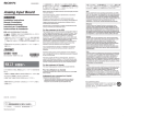
3-203-674-01(1) i.LINK/DV Input/ Output Board JP 設置説明書 3ページ Installation Instructions Manuel d’installation Installationsanleitung Page 11 FR Page 19 DE Seite 27 Istruzioni per l’installazione GB Pagina 35 IT お買い上げいただきありがとうございます。 電気製品は、安全のための注意事項を守らないと、 火災や人身事故になることがあります。 • ご使用にあたっては、デジタルビデオカセットレコーダー本体 に付属の取扱説明書の「安全のために」と「 警告」 、「 注意」 をよくお読みください。お読みになったあとは、いつでも見ら れるところに必ず保管してください。 • 本基板の取り付けは、必ずお買い上げ店またはソニーのサービ ス窓口にご依頼ください。 DSBK-190 1999 by Sony Corporation 日本語 目次 お客様へ ................................................................................. 3 概要 ........................................................................................ 4 DSBK-190 の構成品 ...................................................................... 5 取り付け ................................................................................. 6 お客様へ 6 ページ以降の設置説明 「取り付け」の項)は、特約店およびソニーの ( サービス窓口用の設置説明書です。 お客様がこの設置説明書に記載された作業を行うと、火災や、感電やけ がなどの人身事故につながることがあります。 お客様自身では絶対に取り付け作業をしないでください。 本基板の取り付けは、必ずお買い上げ店またはソニーのサービス窓口に ご依頼ください。 3 JP 日 本 語 取り付け 概要 i.LINK/DVインプット/アウトプットボードDSBK-190は、ソニーデジタルビ デオカセットレコーダー DSR-2000 用のオプション基板です。本基板を DSR-2000に取り付けることにより、2 台の DSR-2000をi.LINK/DV 1) ケー ブルで接続してカット編集システムを構成することができます。また、ソ ニーのコンシューマー用DVカメラと接続して、記録や編集ができるように なります。 DSR-2000に本基板を取り付けた後の接続や操作については、DSR-2000 の取扱説明書をご覧ください。 ....................................................................................................................................................................... 1) 4 は i.LINK のマークです。i.LINKとは IEEE1394-1995 仕様およびその拡 張仕様技術を意味し、ソニーの商標です。 DSBK-190の構成品 DSBK-190は、下図の品目で構成されています。 IF-763基板 外菊ワッシャー ネジ (M3×6、銀色 ) コネクターパネル ハーネス 6ピン ⇔ 4ピンケーブル (1m) 6ピン ⇔ 6ピンケーブル (3.5m) 5 取り付け 取り付け DSBK-190をDSR-2000に取り付ける手順は、以下の通りです。 1 DSR-2000 の天板を外す。 ネジ3本をゆるめて、天板ストッパーおよびブランクパネルから引き出 すようにして外す。 ネジ ブランクパネル ネジ ネジ 天板ストッパー 2 基板押さえを外す。 ネジ1本をゆるめて、基板押さえを持ち上げ、基板押さえガイドがら引 き出すようにして外す。 基板押さえ 基板押さえガイド ネジ 6 3 ブランクパネルを外す。 ご注意 ブランクパネルとネジをなくさないように保管してください。 ネジ ブランクパネル 4 ハーネスを、 コネクターパネル取り付け用開口部を通してコネクターパ ネルに接続した後、コネクターパネルをDSR-2000にネジ止めする。 ハーネス コネクターパネル 付属ネジ(銀色)とワッシャー (続く) 7 取り付け 5 ハーネスをIF-763基板上のケーブルホルダーを通してCN401コネク ターに接続する。 ケーブルホルダー CN-401コネクター IF-763基板 6 IF-763 基板を基板スロット(外側から4 番目)に差し込む。 差し込んだ基板下部の3個のコネクターとDSR-2000本体底部の3個 のコネクターを合わせて、 コネクターが接続されるまで基板をしっかり 押し下げる。 IF-763基板 8 7 ハーネスを、基板スロットの脇のケーブルホルダーに留める。 ケーブルホルダー (続く) 9 取り付け 8 手順 2 で外した基板押さえを元どおりに取りつける。 基板押さえを基板押さえガイドに合わせて押しこんでから、ネジ穴を 合わせてネジを締める。 このとき、基板押さえ下面の6対のツメが、6個の基板スロットに装着 されている基板をそれぞれはさむ位置になっていることを確認する。 基板押さえガイド ネジ 基板押さえのツメ 9 10 DSR-2000 の天板を取り付ける。 English For the customers in the USA This equipment has been tested and found to comply with the limits for a Class A digital device, pursuant to Part 15 of the FCC Rules. These limits are designed to provide reasonable protection against harmful interference when the equipment is operated in a commercial environment. This equipment generates, uses, and can radiate radio frequency energy and, if not installed and used in accordance with the instruction manual, may cause harmful interference to radio communications. Operation of this equipment in a residential area is likely to cause harmful interference in which case the user will be required to correct the interference at his own expense. You are cautioned that any changes or modifications not expressly approved in this manual could void your authority to operate this equipment. GB This device complies with Part 15 of the FCC Rules. Operation is subject to the following two conditions: (1) This device may not cause harmful interference, and (2) this device must accept any interference received, including interference that may cause undesired operation. For the customers in Canada This Class A digital apparatus complies with Canadian ICES003. For the customers in Europe This product with the CE marking complies with the EMC Directive (89/336/EEC) issued by the Commission of the European Community. Compliance with this directive implies conformity to the following European standards: • EN55103-1: Electromagnetic Interference (Emission) • EN55103-2: Electromagnetic Susceptibility (Immunity) This product is intended for use in the following Electromagnetic Environment(s): E1 (residential), E2 (commercial and light industrial), E3 (urban outdoors) and E4 (controlled EMC environment, ex. TV studio). 11 English The shielded interface cable recommended in this manual must be used with this equipment in order to comply with the limits for a digital device pursuant to Subpart B of Part 15 of FCC Rules. Table of Contens Table of Contents Overview ......................................................................... 12 Components of the DSBK-190 ..................................... 13 Installation ...................................................................... 14 Overview The DSBK-190 i.LINK/DV Input/Output Board is an optional board for the DSR-2000/2000P Sony Digital Videocassette Recorder. Installing this board in a DSR-2000/2000P allows two DSR-2000/2000P units to be connected with an i.LINK/ DV 1) cable to form a cut editing system. The board also allows the connection of a Sony consumer DV camera for direct recording and editing. Refer to the DSR-2000/2000P Operating Instructions for information on connecting and operating the DSR-2000/2000P with the DSBK-190 installed. .......................................................................................................................... 1) 12 is a trademark of Sony Corporation, and indicates technology complying with the IEEE1394-1995 specification and extensions thereof. Components of the DSBK-190 The DSBK-190 consists of the following items. IF-763 board Screw (M3 × 6, silver-colored) Washer Connector panel Harness 6-pin/4-pin cable (1 m (3 feet)) 6-pin cable (3.5 m (11 feet)) 13 Installation Caution If this option is installed incorrectly, personal injury or damage to peripheral items may occur due to fire, shock, or other accidental circumstances. To avoid such risks, installation should be performed by qualified service personnel. To install the DSBK-190 in the DSR-2000/2000P, proceed as follows. 1 Remove the top cover of the DSR-2000/2000P. Loosen the three screws, and slide the top cover away from the top retainer and blank panel. Screw Blank panel Screw Screw Top retainer 2 Remove the board retainer. Loosen the screw, then raise the board retainer and pull it out from the board retainer guide. Board retainer Board retainer guide Screw 14 3 Remove the blank panel. Screw Blank panel Notes Keep the blank panel and screw in a safe place for future use. 4 Pass the harness through the opening in which the connector panel fits and connect it to the connector panel; then fasten the connector panel to the DSR-2000/2000P with the screw. Harness Connector panel Supplied screw (silver-colored) and washer (Continued) 15 Installation 5 Pass the harness through the cable holder on the IF-763 board, and connect to connector CN401. Cable holder Connector CN401 IF-763 board 6 Insert the IF-763 board in the board slot (fourth from the outside). Align the three connectors on the bottom of the board with the three connectors inside the unit, and push the board firmly into place. IF-763 board 16 7 Fix the harness in the cable holder by the board slot. Cable holder (Continued) 17 Installation 8 Replace the board retainer which you removed in step 2, in its original position. Push the board retainer into the board retainer guide, and fasten the screw in the screw hole. Check that the six claws on the underside of the board retainer engage with the boards in the slots to hold them in position. Board retainer guide Screw Board retainer claw 9 18 Replace the DSR-2000/2000P top cover. Français Pour les utilisateurs au Canada Cet appareil numérique de la classe A est conforme à la norme NMB-003 du Canada. Pour les clients européens Ce produit portant la marque CE est conforme à la Directive sur la compatibilité électromagnétique (EMC) (89/336/CEE) émise par la Commission de la Communauté européenne. La conformité à cette directive implique la conformité aux normes européennes suivantes: • EN55103-1: Interférences électromagnétiques (émission) • EN55103-2: Sensibilité électromagnétique (immunité) Ce produit est prévu pour être utilisé dans les environnements électromagnétiques suivants: E1 (résidentiel), E2 (commercial et industrie légère), E3 (urbain extérieur) et E4 (environnement EMC contrôlé ex. studio de télévision). FR Français Sommaire Aperçu ............................................................................ 20 Composants de la DSBK-190 ....................................... 21 Installation ...................................................................... 22 19 Aperçu La carte d’entrée/sortie i.LINK/DV DSBK-190 est une carte optionnelle destinée au magnétoscope enregistreur numérique Sony DSR-2000/2000P. Son installation dans le DSR-2000/ 2000P permet le raccordement de deux DSR-2000/2000P avec un câble i.LINK/DV 1) pour former un système de montage de coupures. Cette carte permet aussi la connexion d’une caméra DV grand public Sony pour l’enregistrement et le montage directs. Voir le mode d’emploi du DSR-2000/2000P pour les informations sur le raccordement et le fonctionnement du DSR2000/2000P avec la carte DSBK-190 installée. .......................................................................................................................... 1) 20 est une marque de fabrique de Sony Corporation, et indique que ce produit est conforme aux spécifications IEEE1394-1995 et à leurs amendements. Composants de la DSBK-190 La carte DSBK-190 comprend les éléments suivants. Carte IF-763 Vis (M3 x 6, couleur argent) Rondelle Plaque à connecteur Faisceau Câble 6 broches/4 broches (1 m (3 pieds)) Câble 6 broches (3,5 m (11 pieds)) 21 Installation Attention L’installation incorrecte de cette option pourra engendrer un feu, une décharge électrique ou d’autres circonstances accidentelles, qui pourraient donner lieu à des blessures ou à des dommages pour les éléments périphériques. Pour éviter de tels risques, faites faire l’installation par un personnel de service qualifié. Procédez comme suit pour installer la carte DSBK-190 dans le DSR-2000/2000P. 1 Retirez le cache supérieur du DSR-2000/2000P. Desserrez les trois vis et faites glisser le cache supérieur pour le dégager de la retenue supérieure et de la plaque de suppression. Vis Plaque de suppression Vis Retenue supérieure 22 Vis 2 Retirez la retenue de la carte. Desserrez la vis, puis soulevez la retenue de la carte pour la retirer du guide de retenue de carte. Retenue de la carte Guide de retenue de carte Vis 3 Retirez la plaque de suppression. Vis Plaque de suppression Remarque Rangez la plaque de suppression et la vis à un endroit sûr pour pouvoir les réutiliser ultérieurement. (à suivre) 23 Installation 4 Passez le faisceau dans l’ouverture dans laquelle s’ajuste la plaque à connecteur et raccordez-le à la plaque; puis fixez la plaque au DSR-2000/2000P avec la vis. Faisceau Plaque à connecteur Vis fournie (couleur argent) et rondelle 5 Passez le faisceau dans le support de câble de la carte IF763, et raccordez-le au connecteur CN401. Support de câble Connecteur CN401 Carte IF-763 24 6 Insérez la carte IF-763 dans le logement pour carte (le quatrième à partir de l’extérieur). Alignez les trois connecteurs à la base de la carte sur les trois connecteurs dans l’appareil, et poussez la carte fermement en place. Carte IF-763 7 Fixez le faisceau dans le support de câble au logement de carte. Support de câble (à suivre) 25 Installation 8 Remettez en place la retenue de carte retirée à l’étape 2. Poussez la retenue de carte dans le guide de retenue de carte et serrer la vis dans le trou à vis. Vérifiez que les six ergots sur le dessous de la retenue de carte sont engagés dans les cartes dans les fentes pour les maintenir en place. Guide de retenue de carte Vis Ergot de retenue de carte 9 26 Remettez en place le cache supérieur du DSR-2000. Deutsch Für Kunden in Europa Dieses Produkt besitzt die CE-Kennzeichnung und erfüllt die EMV-Direktive (89/336/EEC) der EG-Kommission. Die Erfüllung dieser Direktive bedeutet Konformität für die folgenden Europäischen Normen: • EN55103-1: Elektromagnetische Interferenz (Emission) • EN55103-2: Elektromagnetische Empfindlichkeit (Immunität) Dieses Produkt ist für den Einsatz unter folgenden elektromagnetischen Bedingungen ausgelegt: E1 (Wohnbereich), E2 (kommerzieller und in beschränktem Maße industrieller Bereich), E3 (Stadtbereich im Freien) und E4 (kontrollierter EMV-Bereich, z.B. Fernsehstudio). Inhaltsverzeichnis 27 DE Deutsch Kurzbeschreibung ......................................................... 28 Die Komponenten der DSBK-190 ................................ 29 Installation ...................................................................... 30 Kurzbeschreibung Die DSBK-190 i.LINK/DV Input/Output Board ist eine optionale Leiterplatte für den digitalen Videorecorder DSR2000P von Sony. Bei Installation dieser Leiterplatte läßt sich der Videorecorder mit einem zweiten DSR-2000P über ein i.LINK/DV1)-Kabel zu einem einfachen Schnittsystem zusammenschließen. Darüber hinaus ist in einem solchen Fall auch der Anschluß einer DV-Kamera von Sony für eine direkte Aufnahme und Schnittbetrieb möglich. Einzelheiten zu den Anschlüssen und der Bedienung des DSR2000P bei installlierter DSBK-190 entnehmen Sie bitte der Bedienungsanleitung des DSR-2000P. .......................................................................................................................... 1) 28 ist ein Warenzeichen der Sony Corporation und gibt an, daß dieses Produkt den Spezifikationen von IEEE1394-1995 und deren Revisionen entspricht. Die Komponenten der DSBK-190 Die DSBK-190 besteht aus den folgenden Komponenten. Leiterplatte IF-763 Unterlegscheibe Schraube (M3x6, silberfarben) Anschlußfeld Kabelbaum 6pol/4pol Kabel (1 m) 6pol Kabel (3,5 m) 29 Installation Vorsicht Bei unsachgemäßer Installation besteht die Gefahr von Verletzungen sowie Schäden an Peripherieausrüstungen aufgrund von Brand, elektrischem Schlag und sonstigen Problemen. Überlassen Sie Installationsarbeiten ausschließlich qualifiziertem Fachpersonal. Zum Einbau der DSBK-190 in den DSR-2000P verfahren Sie wie folgt. 1 Entfernen Sie die Abdeckung des DSR-2000P. Lösen Sie die drei Schrauben und schieben Sie die Abdeckung von der oberen Halterung und der Blindplatte weg. Schraube Blindplatte Schraube Schraube Obere Halterung 30 2 Entfernen Sie die Leiterplattenhalterung. Lockern Sie die Schraube, heben Sie die Halterung und ziehen Sie sie aus der Führung heraus. Leiterplattenhalterung Führung Schraube 3 Entfernen Sie die Blindplatte Schraube Blindplatte Hinweis Bewahren Sie die Blindplatte und die Schraube für spätere Verwendung auf. (bitte wenden) 31 Installation 4 Führen Sie den Kabelbaum, durch die Öffnung für das Anschlußfeld, und schließen Sie sie an das Anschlußfeld an. Sichern Sie dann das Anschlußfeld mit der Schraube am DSR-2000P. Kabelbaum Anschlußfeld Mitgelieferte Schraube (silberfarben) und Unterlegscheibe 5 Führen Sie den Kabelbaum durch den Kabelhalter auf der Leiterplatte IF-763, und schließen Sie ihn an den Steckverbinder CN401 an. Kabelhalter Steckverbinder CN401 Leiterplatte IF-763 32 6 Schieben Sie die Leiterplatte IF-763 in den vierten Schlitz von außen ein. Richten Sie die drei Steckverbinder der Leiterplatte mit den drei Steckverbindern im Innern des Geräts aus, und drücken Sie die Leiterplatte fest ein. Leiterplatte IF-763 7 Sichern Sie den Kabelbaum im Kabelhalter neben dem Leiterplattenschlitz. Kabelhalter (bitte wenden) 33 Installation 8 Bringen Sie die in Schritt 2 entfernte Leiterplattenhalterung wieder an. Drücken Sie die Leiterplattenhalterung in die Führung, und ziehen Sie die Schraube fest. Vergewissern Sie sich davon, daß die sechs Greiferpaare an der Unterseite der Leiterplattenhalterung korrekt in die Leiterplatten eingreifen, um diese in Stellung zu sichern. Leiterplattenhalterung Schraube Greiferpaar der Leiterplattenhalterung 9 34 Bringen Sie die Abdeckung des DSR-2000P wieder an. Italiano Per i clienti in Europa Questo prodotto recante il marchio CE è conforme alla direttiva sulla compatibilità elettromagnetica (EMC) (89/336/CEE) emessa dalla Commissione della Comunità Europea. La conformità a questa direttiva implica la conformità alle seguenti normative europee: • EN55103-1: Interferenza elettromagnetica (Emissione) • EN55103-2: Sensibilità ai disturbi elettromagnetici (Immunità) Questo prodotto è destinato all’uso nei seguenti ambienti elettromagnetici: E1 (residenziali), E2 (commerciali e industriali leggeri), E3 (esterni urbani) e E4 (ambienti EMC controllati, ad esempio studi televisivi). Indice 35 IT Italiano Descrizione .................................................................... 36 Componenti della DSBK-190 ....................................... 37 Installazione ................................................................... 38 Descrizione La scheda di ingresso/uscita i.LINK/DV DSBK-190 è una scheda opzionale per il videoregistratore digitale Sony DSR2000P. L’installazione di questa scheda in un DSR-2000P permette di collegare due DSR-2000P tramite cavo i.LINK/ DV1) per formare un sistema di montaggio di sequenze. La scheda permette inoltre il collegamento di una videocamera DV Sony per consumatori per la registrazione e il montaggio diretti. Fare riferimento alle Istruzioni per l’uso del DSR-2000P per informazioni su come collegare e usare il DSR-2000P con la DSBK-190 installata. .......................................................................................................................... 1) 36 è un marchio di Sony Corporation e indica tecnologia conforme alle specifiche IEEE1394-1995 e relative estensioni. Componenti della DSBK-190 La DSBK-190 consiste dei seguenti elementi. Scheda IF-763 Vite (M3x6, color argento) Rondella Pannello connettori Cablaggio Cavo a 6 piedini/4 piedini (1 m) Cavo a 6 piedini (3,5 m) 37 Installazione Cautela Se questa opzione non viene installata correttamente, si possono verificare lesioni alle persone o danni a unità periferiche dovuti a incendi, scosse elettriche e altri incidenti. Per evitare tali rischi, l’installazione dovrebbe essere eseguita da personale tecnico qualificato. Per installare la DSBK-190 nel DSR-2000P, procedere come segue. 1 Rimuovere il coperchio superiore del DSR-2000P. Allentare le tre viti e far scorrere il coperchio superiore via dal fermo superiore e dal pannello cieco. Vite Pannello cieco Vite Fermo superiore 38 Vite 2 Rimuovere il fermaschede. Allentare la vite, sollevare il fermaschede e tirarlo fuori dalla guida. Fermaschede Guida del fermaschede Vite 3 Rimuovere il pannello cieco. Vite Pannello cieco Nota Conservare il pannello cieco e le viti in un luogo sicuro per usi futuri. (continua) 39 Installazione 4 Far passare il cablaggio attraverso l’apertura in cui entra il pannello connettori e collegarlo al pannello connettori; quindi fissare il pannello connettori al DSR-2000P con la vite. Cablaggio Pannello connettori Vite (color argento) e rondella in dotazione 5 Far passare il cablaggio attraverso il fermacavo della scheda IF-763 e collegarlo al connettore CN401. Fermacavo Connettore CN401 Scheda IF-763 40 6 Inserire la scheda IF-763 nel vano scheda (quarto dall’esterno). Allineare i tre connettori sul fondo della scheda con i tre connettori all’interno dell’apparecchio e spingere saldamente la scheda in posizione. Scheda IF-763 7 Fissare il cablaggio nel fermacavo a fianco del vano scheda. Fermacavo (continua) 41 Installazione 8 Rimettere il fermaschede rimosso al punto 2 nella sua posizione originale. Premere il fermaschede nella guida del fermaschede e fissare la vite nel foro vite. Controllare che le sei linguette sul lato inferiore del fermaschede si aggancino alle schede nei vani per trattenerle in posizione. Guida del fermaschede Vite Linguetta del fermaschede 9 42 Rimettere il coperchio superiore del DSR-2000P. お問い合わせは 「ソニー業務用製品ご相談窓口のご案内」にある窓口へ ソニー株式会社 〒141-0001 東京都品川区北品川6-7-35 ソニーマーケティング株式会社 情報システム営業本部 〒108-0074 東京都港区高輪4-10-18 Printed in Japan