1
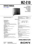
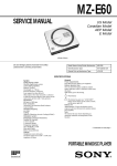
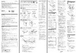
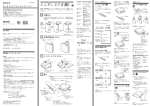
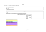
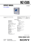
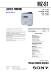
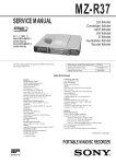
MZ-E300
SERVICE MANUAL
US Model
Canadian Model
AEP Model
E Model
Chinese Model
Ver 1.2 2001.12
US and foreign patents licensed from Dolby
Laboratories Licensing Corporation
Model Name Using Similar Mechanism
NEW
MD Mechanism Type
MT-MZE300-176
Optical Pick-up Mechanism Type
LCX-4E
SPECIFICATIONS
System
Audio playing system
MiniDisc digital audio system
Laser diode properties
Material: GaAlAs
Wavelength: λ = 790 nm
Emission duration: continuous
Laser output: less than 44.6 µW*
* This output is the value measured at a distance of 200 mm from
the objective lens surface on the optical pick-up block with 7 mm
aperture.
Revolutions
Approx. 700 rpm to 1,500 rpm
Error correction
ACIRC (Advanced Cross Interleave Reed Solomon Code)
Sampling frequency
44.1 kHz
Coding
ATRAC (Adaptive TRansform Acoustic Coding)
Modulation system
EFM (Eight to Fourteen Modulation)
Number of channels
2 stereo channels
1 monaural channel
Frequency response
20 to 20,000 Hz ± 3 dB
Wow and Flutter
Below measurable limits
Power requirements
One LR6 (size AA) battery (not supplied)
Battery operation time
Battery life
Battery
LR6 (SG) Sony Alkaline dry battery 2)
(EIAJ1))
Playback
Approx. 33 hours
1)
Measured in accordance with the EIAJ (Electronic Industries
Association of Japan) standard (using a Sony MDW-series Mini-disc).
2)
When using a Sony LR6 (SG) “STAMINA” alkaline dry battery
(produced in Japan).
Note
The effective battery life may be shorter than that indicated above,
depending on operating conditions, the surrounding temperature, and
the battery type.
Dimensions
Approx. 83.0 x 26.7 x 76.5 mm (w/h/d) (3 3/8 x 1 1/16 x 3 1/8 in.)
(not including projecting parts and controls)
Mass
Approx. 83.0 g (3.0 oz) (the player only)
Supplied accessories
Headphones/earphones (1)
Design and specifications are subject to change without notice.
PORTABLE MINIDISC PLAYER
9-873-064-13
Sony Corporation
2001L0200-1
© 2001.12
Personal Audio Company
Published by Sony Engineering Corporation
MZ-E300
SECTION 1
SERVICING NOTE
TABLE OF CONTENTS
Specifications ........................................................................... 1
1. SERVICING NOTE ...................................................... 2
When repairing this device with the power on, if you remove the
main board, this device stops working.
In this case, you work without the device stopping by fastening
the hook of the Open/Close detection switch (S808).
2. GENERAL
Preparing a Power Source .................................................. 3
To Connect the Headphones/Earphones ............................ 3
Playing an MD ................................................................... 3
3. DISASSEMBLY
3-1. “Lid ASSY, Upper”, Holder ASSY ............................
3-2. Mechanism Deck ........................................................
3-3. Main Board .................................................................
3-4. Optical Pick-up ASSY ................................................
4
4
5
5
Open/Close detection switch (S808)
4. TEST MODE .................................................................. 6
Note on IC replacement
5. DIAGRAMS
5-1. Explanation of IC Terminals .....................................
5-2. Block Diagram ..........................................................
5-3. Printed Wiring Boards – Main Section (1/2) – .........
5-4. Printed Wiring Boards – Main Section (2/2) – .........
5-5. Schematic Diagram – Main Section (1/3) – .............
5-6. Schematic Diagram – Main Section (2/3) – .............
5-7. Schematic Diagram – Main Section (3/3) – .............
13
18
19
20
21
22
23
6. EXPLODED VIEWS
6-1. Main Section ............................................................. 29
6-2. Mechanism Deck Section ......................................... 30
7. ELECTRICAL PARTS LIST ................................... 31
CAUTION
Use of controls or adjustments or performance of procedures
other than those specified herein may result in hazardous
radiation exposure.
Flexible Circuit Board Repairing
• Keep the temperature of the soldering iron around 270°C during
repairing.
• Do not touch the soldering iron on the same conductor of the
circuit board (within 3 times).
• Be careful not to apply force on the conductor when soldering or
unsoldering.
Notes on chip component replacement
• Never reuse a disconnected chip component.
• Notice that the minus side of a tantalum capacitor may be damaged by heat.
SAFETY-RELATED COMPONENT WARNING!!
COMPONENTS IDENTIFIED BY MARK 0 OR DOTTED LINE
WITH MARK 0 ON THE SCHEMATIC DIAGRAMS AND IN THE
PARTS LIST ARE CRITICAL TO SAFE OPERATION.
REPLACE THESE COMPONENTS WITH SONY PARTS WHOSE
PART NUMBERS APPEAR AS SHOWN IN THIS MANUAL OR IN
SUPPLEMENTS PUBLISHED BY SONY.
ATTENTION AU COMPOSANT AYANT RAPPORT
À LA SÉCURITÉ!
LES COMPOSANTS IDENTIFIÉS PAR UNE MARQUE 0 SUR LES
DIAGRAMMES SCHÉMATIQUES ET LA LISTE DES PIÈCES
SONT CRITIQUES POUR LA SÉCURITÉ DE FONCTIONNEMENT.
NE REMPLACER CES COMPOSANTS QUE PAR DES PIÈCES
SONY DONT LES NUMÉROS SONT DONNÉS DANS CE MANUEL
OU DANS LES SUPPLÉMENTS PUBLIÉS PAR SONY.
2
If using flux on replacing IC801 etc., clean it with alcohol or
equivalent, and after that, check carefully there are no dust or
rags in between pins.
Especially, be sure to check between pins 4 and 5.
SECTION 2
GENERAL
MZ-E300
This section is extracted from
instruction manual.
3
MZ-E300
SECTION 3
DISASSEMBLY
• The equipment can be removed using the following procedure.
Set
“Lid ASSY, Upper”,
Holder ASSY
Main board
Mechanism deck
Optical pick-up ASSY
Note : Follow the disassembly procedure in the numerical order given.
3-1. “LID ASSY, UPPER”, HOLDER ASSY
Note : Holder ASSY installation
1. Attach the holes on Holder ASSY to the projections on right and left sides.
2. Attach Spring (POP/L) as shown in the figure.
3 Lid ASSY , Upper
1 Screws (1.4),MI
2 Move it away
from projection
Holder ASSY
Reinforcement
4 Move it away
from projection
Spring (POP/L)
5 Holder ASSY
4 Move it away
from projection
Case ASSY
3-2. MECHANISM DECK
1 Screw (MD), step
Mechanism deck
2
5 Motor flexible board
6 OP flexible board
7 Screws, tapping (1.7)
4
8
Reinforcement
3 Claw
Case ASSY
4
MZ-E300
3-3. MAIN BOARD
Note : On installation of main board, adjust the position of
both switch (S809) and knob (HOLD).
1 Screws, tapping (1.7)
Main board
3
Knob (HOLD)
2 Claw
3-4. OPTICAL PICK-UP ASSY
Optical pick-up ASSY
(LCX-4E)
1 Washer
2 Gear (SA)
5
3 Screw (MI 1.4)
4 Spring, thrust detent
5
MZ-E300
SECTION 4
TEST MODE
4-1. GENERAL
Lead wires: 4 leads
• When entered in the TEST MODE, this set provides the Overall
Adjustment mode which allows CD and MO discs to be automatically adjusted. In the Overall Adjustment mode, performs
adjustments in sequence automatically, and displays the faulty
location if any fault is found. In the Manual mode, selected adjustments can be performed automatically.
• Operations in the Overall Adjustment mode can be performed
either via the main unit, or the keys of a remote control unit.
Note that this device does not include a remote control unit.
Therefore, since no connection terminals for a remote control
are provided either, a connection device must be used in order
to allow a suitable remote control unit to be connected.
4-2. SETTING THE TEST MODE
BP801
(TEST) C806
TP809
C8
R830
C810
MAIN BOARD (SIDE A)
15
R803
FB801
Connection
Following parts are required
Remote commander: RM-MZ2N (1-418-493-71)
After RM-MZE1 applicable to 2.4V
(Not applicable to remote commanders
before RM-MZE1).
Jack: 7 poles jack for phones/remote commander (1-793-288-61)
4-2-1. How to set the TEST MODE
To set the TEST MODE, three methods are available.
1 Solder bridge and short BP801 (TEST) on the main board.
Then turn on the power.
TP808 R907
20
21
C80
X801
TP816
C805 R82
R_VDD
R_DATA
R_KEY
R_GND
JACK: 1-793-288-61
4 3 2 1
MAIN BOARD
(SIDE A)
1
2
TP804
3
BP801
OPEN : Normal mode
SHORT : Test mode
2 Using a pair of tweezers or similar tool short-circuit TP804 and
TP805 on the main board and turn on the power.
4
TP803 TP802 TP801
TP805 TP806 TP951
MAIN BOARD
(SIDE A)
TP804 TP805
TP804
TP803 TP802 TP801
TP805 TP806 TP951
3 In the normal mode, operate the keys on the set and those on the
remote control as specified below:
Turn on HOLD switch on the set. Holding down x (STOP)
key on the set, press the keys on the remote control in the
following sequence:
>N t >N t . t . t >N
t . t >N t . t X t X
6
MZ-E300
Ver 1.2 2001.12
4-2-2. Operations when the TEST MODE is set
When the TEST MODE is entered, the system switches to the display check mode within the TEST MODE. From this mode, the
other Test modes can be accessed.
When the TEST MODE is set, the LCD repeats a cycle of the following displays:
Main unit LCD
4-3. TEST MODE STRUCTURE
* Manual mode operation can only be performed via the remote
control unit.
Use the connection tool to connect the remote control unit. The
display of the main unit shows “Adj”.
Test Mode
(Display Check Mode)
F 1SHUFF
AVLS BASS
+ key
u
888:88
Manual Mode
(Remote control only)
x
All on
key
+ key
Servo Mode
Audio Mode
All off
Power Mode
130
key
Microprocessor
version
display
OP Alignment Mode
Press and hold
down x key
Display segment check mode
(Main unit only)
Remote control LCD
Release
888
F 1SHUFF PGM u
SOUND 1 2 BASS 1 2
.
or
x
key
key
Overall Adjustment Mode
All on
x
key
4-4. MANUAL MODE
All off
4-4-1. Outline of the function
008 V1.300
Microprocessor
version
display
The remote control display varies with the type of
remote control unit used.
(Example shown: RM-MC10L)
• The current display is retained as long as either the PLAY
MODE/DISPLAY key on the main unit or the PLAY MODE
key on the remote control unit is pressed and held.
4-2-3. How to release the TEST MODE
When method 1 was used:
Turn off the power and open the solder bridge on BP801 on the
main board.
Note: The solder should be removed clean. The remaining solder
may make a short with the chassis and other part.
When method 2 or 3 was used:
Turn off the power.
Note: If electrical adjustment (see page 8) has not been finished
completely, always start in the test mode. (The set cannot
start in normal mode)
The Manual mode is designed to perform adjustments and
operational checks on the set’s operation according to each
individual function.
Usually, no adjustments are made in this mode.
However, the Manual mode is used to clear the memory before
performing automatic adjustments in the Overall Adjustment mode.
* Manual mode operation can only be performed via the remote
control unit.
Use the connection tool to connect the remote control unit. The
display of the main unit shows “Adj”.
4-4-2. How to set the Manual mode
1. Set the TEST MODE and press + key to set the Manual mode.
Remote control LCD display
000 AAAS CC
2. When the test mode display shows “100”, “200”, “300”, “500”,
“600”, “700”, “800”, or “900”, the optical pickup can be moved
inside and outside of the SLED perimeter by continuously pressing the ( > N or . keys on the main unit.
7
MZ-E300
3. Each test item is assigned with a three-digit item number. The
100th place is a major item, 10th place is a middle item, and unit
place is a minor item.
Change Major
Item
> N key
x
x
4-5-1. Outline of the function
+ key : 100th place of mode number
increase
key : 100th place of mode number
decrease
This mode is designed to adjust the servo system automatically by
going through all the adjustment items.
Usually, this mode is used to perform automatic adjustments when
servicing the set.
+ key : 10th place of mode number
increase
key : 10th place of mode number
decrease
4-6. NV RESET
key
Change Middle
Item
> N key
4-5. OVERALL ADJUSTMENT MODE
key
> N key : Unit place of mode number
Change Minor
Item
increase
. key : Unit place of mode number
Power: Connect the battery terminals to a stable DC 1.5V power
supply, or insert fresh batteries (size “AA”, IEC “LR6”).
Two different methods apply for NV reset, depending on whether
the main unit or a remote control unit is used.
NV reset via main unit
1. Enter test mode.
decrease
Change Adjustment
Value
+ key : Up
key : Down
2. Use the – key or the . key to set the device to Overall
Adjustment mode.
Write Adjustment
Value
ASS
X key : When adjusted value is changed :
Adjusted value is written.
When adjusted value is not changed :
That item is adjusted automatically.
4. During each test mode, the display is changed from one to
another each time DISPLAY key is pressed (Remote control
only).
3. Press the PLAY MODE/DISPLAY key. “CL” starts to flash.
AdJ cL
4. Press the PLAY MODE/DISPLAY key once more. “CL” stops
flashing and remains lit, thus concluding NV reset.
Address Value & Adjustment Value
AdJ cL
LCD display
011 XXXSXX
5. Press the x key to return to test mode.
Block Error Value & Adjustment Value
LCD display
011 XX BXX
ADIP Error Value & Adjustment Value
LCD display
011 XX AXX
Jitter Value & Adjustment Value
LCD display
* Functions are displayed,
but cannot be used via
this unit.
011 XXXJXX
NV reset via remote control
1. Set the TEST MODE.
2. Set the Manual mode and set the item No. 021, Reset NV.
LCD display
021 AAAS CC
3. Press X key on the remote control.
LCD display
Power Adjustment Value
021 AAAS CC
LCD display
731 XX VXX
4. Press X key on the remote control again.
After the voltage indicator appears,
press the DISPLAY key twice.
Memory Monitor Mode
LCD display
XXX: Each Value
XX: Adjustment Value
for Item number
Note: In the Power mode, the item title display is only displayed.
5. To terminate the Manual mode and return to the TEST MODE,
press x key.
8
Flash CC
021 AAAS CC
5. Press x key to terminate the Manual mode and return to the
TEST MODE.
MZ-E300
4-6-1. Electrical offset adjustment method
Note: Doing adjustment by the state that a disc does not enter.
1. Confirm the power voltage is 1.5V.
2. Set to the test mode.
3. Press the – key of main unit activates the overall adjustment
mode.
Main unit LCD display
4-7. OVERALL ADJUSTMENT MODE
4-7-1. Overall adjustment mode structure
TEST MODE
(Display Check Mode)
VOL – key or . key
ASS
Overall Adjustment
Title Display(ASSY**)
. key
4. Press the + key.
x
CD overall
Adjustment
> N key
Main unit LCD display
> N key
MO overall
Adjustment
5. Press the + key once more. Adjustment is complete when the
adjustment value appears in the “XX” position.
VOL + key
Electrical offset
Adjustment key
4-6-2. Display segment check mode
1. Enter test mode. Display continuously alternates between the
following three conditions: entire LCD is lit, entire LCD is extinguished, version info is shown, and so on.
PLAY MODE/DISPLAY key
035: XX
2. Press and hold the x key on the main unit to enter display
segment check mode.
* Should segments not be displayed correctly at this point, a shortcircuited COM terminal and/or SEG terminal on the microprocessor chip (IC801) are possible causes.
3. Display returns to condition “1” as soon as the x key is released.
key
x
x
NV reset
key
x
key
key
Perform overall adjustments according to the following procedures
(procedures may differ depending on the microprocessor chip
version used).
For Ver. 1.10, if it is no good in the overall adjustment, please
repeat the overall adjustment several times.
Microprocessor Version 1.10
1 Clear NV.
2 Electric offset adjustment.
3 Rewriting of RAM 633h
1. switch to manual mode No. 100.
2. Press the DISPLAY key on the remote control unit 6 times
consecutively to enter RAM mode.
3. Change the RAM address to 633h.
Use the following keys on the remote control unit to change
the digits of the RAM address:
“The DISPLAY key for the first digit (hundreds), the x key
for the second digit (tens) and the >B key or the .
key for the third digits (units).”
4. Use the + and – keys on the remote control unit to set the
adjustment value of No.633h to 03h and press once the pause
key on the remote control unit to write this value to NV.
“(If NV is cleared, the value is 00h.)
5. Press the DISPLAY key once more to change the display
to “address and adjustment value display”.
6. Switch to the overall adjustment.
4 CD overall adjustment * (Not to turn off the power between the
items 3 and 4 .)
9
MZ-E300
Ver 1.1 2001.03
5 Rewriting of the adjustment value.
1.After CD overall adjustment, switch to manual mode No. 321
in the condition the disc is in.
2.Press – key on the remote control unit to set 1 step down the
adjustment value of No. 321, and press the pause key on the
remote control unit to write this value to NV.
3.Press the >B key on the remote control unit to switch to
manual mode No. 323.
4.Press the pause key on the remote control unit to set to the
automatic adjustment.
During adjusting automatically, the adjustment value turns on
and off, so wait for the time the adjustment value is on.
5.Press the >B key on the remote control unit to switch to
manual mode No. 345.
6.Note down the current adjustment value of No. 345 (value X).
Use the + and – keys on the remote control unit to set the
adjustment value of No. 345 to the value (Y) determined by
the formula below, and press the pause key on the remote
control unit to write this value to NV.
Formula: X x 1.18 = Y
* Since X and Y are 2’sC, attention must be paid to codes.
And the maximum value of Y must be 7Fh. (Never set it to
the negative value.)
Example: Since X = 2Bh, Y = 2Bh x 1.18 = 33h
6 Change the disc to MO overall adjustment disc (GA1 disc).
Switch to manual mode No.114.
Press the pause key on the remotecontrol unit to set to the
automatic adjustment.
After adjustment, pull out the battery from the set to turn off
the power.
Then insert the battery again.
7 MO overall adjustment.
Microprocessor Version 1.20 and higher
5 Change the disc to MO overall adjustment disc (GA1 disc).
Switch to manual mode No.114.
Press the pause key on the remotecontrol unit to set to the
automatic adjustment.
After adjustment, pull out the battery from the set to turn off
the power.
Then insert the battery again.
6 MO overall adjustment.
4-7-2. Overall CD and MO adjustment method
1. Set the TEST MODE and press VOL – key or . key to set
the Overall Adjustment mode.
Main unit LCD display
ASS
2. Insert CD disc in the set, and press . key to set the Overall
CD Adjustment mode.
Automatic adjustments are made.
Main unit LCD display
XXX:
XXX: Item No. for which an adjustment is being executed.
YY: Adjustment Value
3. If NG in the overall CD adjustments, return to Reset NV and
perform from the electrical offset adjustment again.
The NG item and “ng” alternately flash on the main unit LCD
display.
1 Clear NV.
2 Electric offset adjustment.
XXX:
3 CD overall adjustment.
4 Rewriting of the adjustment value.
1.After CD overall adjustment, switch to manual mode No. 321
in the condition the disc is in.
2.Press – key on the remote control unit to set 1 step down the
adjustment value of No. 321, and press the pause key on the
remote control unit to write this value to NV.
3.Press the >B key on the remote control unit to switch to
manual mode No. 323.
4.Press the pause key on the remote control unit to set to the
automatic adjustment.
During adjusting automatically, the adjustment value turns on
and off, so wait for the time the adjustment value is on.
5.Press the >B key on the remote control unit to switch to
manual mode No. 345.
6.Note down the current adjustment value of No. 345 (value X).
Use the + and – keys on the remote control unit to set the
adjustment value of No. 345 to the value (Y) determined by
the formula below, and press the pause key on the remote
control unit to write this value to NV.
Formula: X x 1.18 = Y
* Since X and Y are 2’sC, attention must be paid to codes.
And the maximum value of Y must be 7Fh. (Never set it to
the negative value.)
Example: Since X = 2Bh, Y = 2Bh x 1.18 = 33h
n
XXX: NG item No.
YY: Adjustment Value
4. If OK through the overall CD adjustments, then perform overall
MO adjustments.
Main unit LCD display
End:cd
5. Insert MO disc in the set, and press > N key to set the
Overall MO Adjustment mode. Automatic adjustments are made.
Main unit LCD display
XXX:
XXX: Item No. for which an adjustment is being executed.
YY: Adjustment Value
10
MZ-E300
6. If NG in the overall MO adjustments, return to Reset NV and
perform the adjustment again.
The NG item and “ng” alternately flash on the main unit LCD
display.
XXX:
n
XXX: NG item No.
YY: Adjustment Value
7. If OK through the overall MO adjustments, press x key to
return to the TEST MODE and terminate the Overall Adjustment mode.
Main unit LCD display
11
MZ-E300
4-7-3. Overall CD and MO adjustment items
1. Overall offset adjustment
Item No.
Description
Item No.
Description
100h
GRV setting servo off
030h
GRV setting servo off
112h
ALFA offset adjustment
035h
Laser ON/OFF Electric offset differential
measurement
113h
IJ offset adjustment
114h
FE offset adjustment
118h
AW_DW_OFFSET
200h
LPIT setting servo off
2. CD overall adjustment
Item No.
300h
Description
HPIT setting servo off
312h
ALFA offset adjustment
313h
IJ offset adjustment
314h
FE offset adjustment
571h
CLV start
561h
Move to inside of SLED perimeter
562h
Move to outside of SLED perimeter
320h
Focus on
323h
TE offset adjustment
321h
TE gain adjustment
328h
TWPP gain adjustment
829h
TWPP gain [LPIT] adjustment value write
323h
TE offset adjustment
324h
OFTRK adjustment
330h
Tracking ON
336h
ABCD gain adjustment
337h
KF gain adjustment
338h
RF gain adjustment
344h
FOCUS gain adjustment
345h
Tracking gain adjustment
521h
Twin axis sensitivity compensation (inside perimeter)
571h
CLV START
561h
Move to inside of SLED perimeter
220h
Focus on
223h
TE offset adjustment
221h
TE gain adjustment
223h
TE offset adjustment
226h
Tracking Drive Voltage = “00h” setting
230h
Tracking ON
236h
ABCD gain adjustment
237h
KF gain adjustment
238h
RF gain adjustment
244h
Focus gain adjustment
245h
Tracking gain adjustment
110h
GRV setting servo off (CLV remains as is)
562h
Move to outside of SLED perimeter
120h
Focus on
122h
TE offset adjustment (TON)
121h
TE gain adjustment
122h
TE offset adjustment (TON)
123h
TE offset adjustment (TEIN)
124h
TE offset adjustment (TWPP)
125h
OFTRK adjustment
130h
Tracking ON
522h
Twin axis sensitivity compensation (outside
perimeter)
341h
Field of vision oscillation check
144h
Focus gain adjustment
HPIT setting servo OFF
145h
Tracking gain adjustment
139h
bpf f0 adjustment
131h
TE offset adjustment (TWPP/RF)
132h
TE offset adjustment (TWPP/DSP)
136h
ABCD gain adjustment
137h
KF gain adjustment
134h
TWPP gain adjustment
131h
TE offset adjustment (TWPP/RF)
132h
TE offset adjustment (TWPP/DSP)
138h
RF gain adjustment
141h
Field of vision oscillation check
100h
GRV setting servo OFF
300h
12
3. MO overall adjustment
MZ-E300
SECTION 5
DIAGRAMS
5-1. EXPLANATION OF IC TERMINALS
• IC601 LC89642-8B-E
(DIGITAL SIGNAL PROCESSOR, DIGITAL SERVO SIGNAL PROCESSOR, ATRAC ENCODER/DECODER,
8MBIT D-RAM, D/A CONVERTER)
Pin No.
Pin name
I/O
Description
1
FR
I
Connected to Bias resistor for VTEC oscillating frequency
2
ISET
I
Connected to Bias resistor for VTEC current charge pump
3
VCVDD
—
Power supply for VTEC
4
PDD
O
VTEC current charge pump output
5
TEST3
I
Input for test
6
TEST2
I
Input for test
7
SLCO
O
Slice level output for HF signal
8
SLCIST
I
Connected to Bias resistor for the slice level adjusting amplifier
9
EFMIN
I
HF signal input
10
RESETB
I
System reset
11
TEST1
I
Input for test
12
HFL
I
Track detection signal input
13
VDD2
—
Power supply
14
VSS
—
Ground
15
VDD1
—
Internal power supply
16
AVSS1
—
Ground for digital servo
17
PEAK
I
PEAK signal input
18
BOTTOM
I
BOTTOM signal input
19
ABCD
I
Main beam quantity signal input
20
TE
I
Tracking error signal input
21
FE
I
Focus error signal input
22
VC
I
Center potential input
23
AVDD1
—
Power supply for digital servo
24
MAD9
O*
Address output to DRAM (NC)
25
DSW1
O*
Disc mode select output
26
MAD8
O*
Address output to DRAM (NC)
27
DSW0
O*
Disc mode select output
28
MAD7
O*
Address output to DRAM (NC)
29
SGC
O*
AGC control signal output
30
MAD6
O*
Address output to DRAM (NC)
31
AOFFSET
O*
ABCD offset control signal output
32
MAD5
O*
Address output to DRAM (NC)
33
FOFFSET
O*
Focus offset control signal output
34
TOFFSET
O*
Tracking offset control signal output
35
MAD4
O*
Address output to DRAM (NC)
36
TBAL
O*
Tracking balance control signal output
37
LDREF
O*
Laser control signal output
38
FBAL
O*
Focus balance control signal output
39
VDD1
—
Internal power supply
40
VSS
—
Ground
41
VDD2
—
Power supply
42
MAD3
O*
Address output to DRAM (NC)
43
SPPWMF
O*
Spindle PWM output
44
SPPWMR
O*
Spindle PWM output
45
SLPWMF
O*
Sled PWM output
13
MZ-E300
Pin No.
Pin name
I/O
46
MAD2
O*
47
SLPWMR
O*
Sled PWM output
48
MAD1
O*
Address output to DRAM (NC)
49
FOPWMF
O*
Focus PWM output
50
MAD0
O*
Address output to DRAM (NC)
51
FOPWMR
O*
Focus PWM output
52
TRPWMF
O*
Tracking PWM output
53
TRPWMR
O*
Tracking PWM output
54
MAD10
O*
Address output to DRAM (NC)
55
AVDD
—
Power supply for 1bit DAC
56
OUTL
O
1bit DAC L channel output
57
OUTR
O
1bit DAC R channel output
58
AVSS
—
Ground for 1bit DAC
59
VDD2
—
60
XIN
I
16.9344MHz oscillation input
61
XOUT
O
16.9344MHz oscillation output
62
VSS
—
Ground
63
VDD1
—
Internal power supply
64
F16M
O*
16.9344MHz output
65
ENH
O*
De-emphasis instruction output
66
LRCO
O*
LR clock output
67
DDATA
O*
Audio expansion data output
68
BCO
O*
Bit clock output
69
DDOUT
O*
Digital audio output
70
SMON3
O*
Monitor signal output
71
SMON2
O*
Monitor signal output
72
SMON1
O*
Monitor signal output
73
SMON0
O*
Monitor signal output
74
FSEQ
O*
Frame sync. detection signal output
75
VP
O*
CLV servo lock decision output
76
MRASBT
O*
Output for test
77
MRASB
O*
RAS signal output to DRAM (NC)
78
FOK
O*
Focus OK signal output
79
NWEB
O*
WE signal output to DRAM (NC)
80
DEFECT
O*
Defect signal output
81
MD1
I/O
Data input/output to/from DRAM
82
FG
I
Speed pulse input
83
CL
I
Data transferring clock input for CPU interface
84
CE
I
Chip enable signal input for CPU interface
85
MDO
I/O
86
DI
I
87
VDD1
—
power supply
88
DO
O
Data output for CPU interface
89
VDD2
—
Power supply
90
VSS
—
Ground
91
MD3
I/O
Data input/output to/from DRAM
92
WRQB
O
Interruption output for CPU interface
93
INTB
O
Interruption output for CPU interface
94
ADIPWO
I
Wobbly signal input
14
Description
Address output to DRAM (NC)
Power supply
Data input/output to/from DRAM
Data input for CPU interface
MZ-E300
Pin No.
Pin name
I/O
Description
95
MD2
I/O
Data input/output to/from DRAM
96
SHOCK
O*
SHOCK/RFNG output
97
MCASB
O*
CAS signal output to DRAM (NC)
98
PCK
O
VTEC system clock signal output
99
MOEB
O*
OE signal output to DRAM (NC)
100
VCVSS
—
Ground for VTEC
* : I/O on the test mode.
15
MZ-E300
• IC801 RU6615MF-0003 (SYSTEM CONTROL)
Pin No.
Pin name
I/O
Description
1
UNREG_MON
I
2
RF_VCMON
I
Reference voltage (1.2V) for adjusting power supply voltage input (A/D input)
3
RMC_KEY
I
Remote commander with phones key input (A/D input)
4
SET_KEY
I
5
OPEN_CLS_SW
I
Upper panel open/close detection switch (S808) input L: Close, H: Open
6
RF_SMON
I
S-MON level input from SN761057DBT (IC501) (A/D input)
7
DSP_SMON3_LP
—
8
VL_MON
I
9
XRESET
I
10
AVDD
—
Power supply (2.48V) (For A/D conversion)
11
AVSS
—
Ground (For A/D conversion)
UNREG voltage monitor input (A/D input)
Key on the set itself input (A/D input) S801-807 (STOP, FF/PB, REW/PB, VOL+, VOL-,
PLAY MODE, DBB/AVLS key input
Not used (Fixed to L)
VL voltage monitor input from XPC18A32FCR2 (IC901) (A/D input)
System reset signal input from XPC18A32FCR2 (IC901) (A/D input) L: Reset L is in
while 500-600 msec after power turns on, and then turns to H.
12, 13
TYPE0, 1
I
Initial setting for the model decision input (Bit 0, 1) Fixed to L.
14
XADJUST
I
Test mode setting input L: Test mode (Fixed to H normally)
15
HOLD_SW
I
HOLD switch (S809) input L: Off, H: On
16
XOUT
O
Main system clock (16.9344MHz) output
16
17
XIN
I
Main system clock (16.9344MHz) input
18
HP_MUTE
O
Muting on/off control signal output to phones amplifier (IC301) H: Muting on
19
HP_STBY
O
Standby on/off control signal output to phones amplifier (IC301) L: Standby, H: Amp. on
20
XCLK
O
Clock (16.9344MHz) output to LC89642-8B-E (IC601)
21
VDD
—
Power supply (+2.1V) (Digital system)
22
VSS
—
Ground (Digital system)
23
DSP_WRQB
I
SUBQ/ADIP read out request input from LC89642-8B-E (IC601) L: Request
24
DSP_INTB
I
SPP, servo status read out request input from LC89642-8B-E (IC601) L: Request
25
DSP_SMON3
I
Monitor signal 3 input from LC89642-8B-E (IC601)
26
DSP_CE
O
Chip enable output to LC89642-8B-E (IC601) H: Enable
27
PWR_FFCLR
O
Latch clear signal for start up signal to XPC18A32FCR2 (IC901) output H: Clear
28
PWR_SLEEP
O
System sleep control signal to XPC18A32FCR2 (IC901) output H: Sleep on
29
PWR_VLON
O
VL voltage control signal to XPC18A32FCR2 (IC901) output H: VL out on
30
PWR_CLKSEL
O
31
SBUS_CLK
O
32
SBUS_DATA
I/O
33
PD_S1
O
PD-IC mode select signal output L: PIT, H: GRV
34
SLD_1_MON
I
Sled servo timing signal input from SC111257FCR2 (IC551)
35
SLD_2_MON
I
Sled servo timing signal input from SC111257FCR2 (IC551)
36
CLV_VCON
O
Spindle servo drive voltage control signal output to SC111257FCR2 (IC551)
37
SLD_VCON
O
Sled servo external voltage control signal output to SC111257FCR2 (IC551)
38
VC_VCON
O
PWM signal for VC voltage control signal to XPC18A32FCR2 (IC901) output
39
CLV_U_MON
I
Spindle servo (U) timing signal input from SC111257FCR2 (IC551)
40
VDD
—
Power supply (+2.1V) (Digital system)
41
VPP
—
Test (Fixed to L)
External sync. 2 division circuit control signal to XPC18A32FCR2 (IC901) output L: 2
division, H: No division
SSB serial clock signal output to SN761057DBT (IC501)
SSB serial data signal input/output to SN761057DBT (IC501)
42
CLV_V_MON
I
Spindle servo (V) timing signal input from SC111257FCR2 (IC551)
43
CLV_W_MON
I
Spindle servo (W) timing signal input from SC111257FCR2 (IC551)
44
CLV_U_CON
O
Spindle servo (U) drive signal output to SC111257FCR2 (IC551)
45
CLV_V_CON
O
Spindle servo (V) drive signal output to SC111257FCR2 (IC551)
MZ-E300
Pin No.
Pin name
I/O
Description
46
CLV_W_CON
O
47
SLED_1R_CON
O
Sled motor control signal output to SC111257FCR2 (IC551)
48
SLED_1F_CON
O
Sled motor control signal output to SC111257FCR2 (IC551)
49
SLED_2R_CON
O
Sled motor control signal output to SC111257FCR2 (IC551)
50
SLED_2F_CON
O
Sled motor control signal output to SC111257FCR2 (IC551)
Spindle servo (W) drive signal output to SC111257FCR2 (IC551)
51
BEEP
O
Beep sound drive signal output to phones amplifier (IC301)
52
NV_XCS
O
Chip select signal output to EEPROM (IC802)
53
RMC_DTCK
I/O
54
SIO2_CLK
O
TSB serial communication data input/output to/from remote commander with phones
Serial clock signal output to LC89642-8B-E (IC601) and EEPROM (IC802)
55
SIO3_DI
I
Read data input from LC89642-8B-E (IC601) and EEPROM (IC802)
56
SIO3_DO
O
Write data output to LC89642-8B-E (IC601) and EEPROM (IC802)
57
DSP_VP
I
CLV servo lock decision signal input from LC89642-8B-E (IC601)
58
VL_VCON
O
PWM signal for VL voltage control signal to XPC18A32FCR2 (IC901) output
59
PWR_CLK
O
External sync. clock (176.4kHz) signal to XPC18A32FCR2 (IC901) output
60
SEG0
O
LCD segment output
61
VSS
—
Ground (Digital system)
62-72
SEG1-11
O
LCD segment output
73-76
COM0-3
O
LCD common output
77-79
VL1, 2, LVDD
I
LCD drive level power supply input
80
VSS
—
Ground (Digital system)
17
17
MZ-E300
5-2. BLOCK DIAGRAMS
MAIN BOARD
Iy
6
VREF
DIGITAL SIGNAL PROCESSOR,
DIGITAL SERVO SIGNAL PROCESSOR,
ATRAC ENCODER/DECODER,
8M BIT D-RAM, D/A CONVERTER
HEADPHONE AMP
IC601
IC301
4 VREF
RCH
Iy
8
9
10
11
12
14
5
6
9
Ix
10
Jx
14
Jy
15
A
16
B
17
C
7
8 D
Jy
Jx Jy Jx
A
Ix Iy Ix
B
Iy
Ix
Jx
Jy
A
B
C
D
A-C
13
D-C
7
C
18
D
MON
18
PD-I
RF OUT
RF AMP,
FOCUS
ERROR,
TRACKING
ERROR
PEAK
PEAK
/BOTM
BOTM
ABCD
33
9 EFMIN
29
28
17 PEAK
18 BOTTOM
41
19 ABCD
42
21 FE
1
ADIP IN 44
20 TE
FE
TE
TPP/WPP
PD-NI
37 LDREF
19
VC 31
VIF
PD
2 RFVC MON
OFTRK 26
22 DVDD
5
12
LD
LASER
AUTO POWER
CONTROL
Q501
20
S-MONITOR
PD-O
S MON
10 RESET B
S1
AVCC
43
2 VOUT VIN 3
2
DO 88
20
23
24
25
26
57
XIN 60
92
93
70
84
75
WRQB
INTB
SMON3
CE
VP
38
41
40
FOCUS
COIL
3
DSP WRQB
DSP INTB
DSP SMON3
DSP CE
DSP VP
34 SLD1MON
37
39
4
PRE
DRIVER
24
25
HI-BRIDGE
CONTROL
EEPROM
BEEP 51
HP STB 19
MUTE 18
NV XCS 52
S102 CLK 54
S102 DO 56
S102 DI 55
SEG0 60
LIQUID
CRYSTAL
DISPLAY
SEG11 72
COM0 73
HOLD SW 15
SET KEY 4
OFF
ON
OPEN CLS SW 5
X801
16.9344MHz
BIAS
FCS+
S809
HOLD
S807
DIGITAL
MEGABASS/
AVLS
S806
S805
PLAY MODE VOLUME
/DISPLAY
–
FCS-
IC901
44 VD
PRE
DRIVER
HI-BRIDGE
CONTROL
19
18
5 XWK4
2 XWK1
RMC KEY 3
UNREG MON 1
5
7
SLED2+ 6
SLED2- 8
28
29
31
1
PRE
DRIVER
PRE
DRIVER
HI-BRIDGE
CONTROL
HI-BRIDGE
CONTROL
54
51
47 SLED 1R CON
48 SLED 1F CON
37 SLD VCON
16
17
20
26
27
50 SLED 2F CON
49 SLED 2R CON
XCS NV
SI0
39 CLV U MON
SCK0
1
52
56
42 CLV V MON
S00
55
43 CLV W MON
2
3
4
5
6
46 CLV W CON
45 CLV V CON
44 CLV U CON
36 CLV VCON
UNREG
PWR CLK
PWR VLON
PWR SLEEP
PWR FFCLR
XRST
AVDD
VL MON
59
29
28
27
9
10
8
7
4
6
3
VRMC
XWK3
VSTB
XWK2
26 INM1
27 RF1
23 RF2
VC VCOM 38
VL VCOM 58
VL
S804
VOLUME
-+
S803
.
53
22
56
1
55
54
46
36
34
INM2
CLK
VLON
SLEEP
FFCLR
XRST
VC
VC
45 VC2
VCO 35
VIF 42
VC
VIF
AVDD
VA 41
VG 19
VG
D903
LG 18
UNREG
VL 9
VL 11
D902
L2 16
L2 12
VB 50
L1 32
L1 28
CLVU
CLVV
CLVW
48
2
45
46
49
44
3
4
PRE
DRIVER
3 PHASE
CONTROL
52 CLK SEL VC OUT 33
PWR CLKSEL 30
S801
x
VL
VLO 10
D901
M901
(SPINDLE)
S802
>N
POWER SUPPLY
16 XOUT
DVDD
14
15
12
SLED1-
IC803
IC802
17 XIN
CN551
SLED1+
3 STATE BUFFER
S808
(OPEN/CLOSE)
35
36
11
10
7
REFERENCE
VOLTAGE
SWITCHING
Q301
VREF IN 13
35 SLD2MON
8
MINIDISC
MECHANISM BLOCK
M902
(SLED)
BEEP
COM3 76
42
1
XCLK
32 S BUS DATA
31 S BUS CLK
6 RF SMON
IC551
TRK-
24
23
4
IC801
49 FOPWMF
51 FOPWMR
33
32
BEEP OUT B
15
18 STB
17 MUTE
3
13
41
59
89
33 PD S1
TRK+
BEEP OUT A
VC
VA
VCVDD
VDD2
VDD2
VDD2
VDD2
1 +B
20 VCC
SYSTEM CONTROL
52 TRPWMF
53 TRPWMR
MINIDISC
OPTICAL PICK-UP BLOCK
(LCX-4E)
TRACKING
COIL
VIF
IC602
FOCUS/TRACKING COIL DRIVE,
SPINDLES/SLED MOTOR DRIVE
2
UNREG
REGULATOR
19
S1
J301
i
RCH
VD
VDD1 15
VDD1 63
VDD1 87
22 VC
20
11
S0
4
OUT B
IN B
Q801
AVCC
AVCC
S0
21
OUT R 57
1
13
LD-K
LCH
DI 86
XRST
25
SBUS
23
SCK
24
SERIAL
I/F
LD-A
12 HFL
2
RCH
AVDD 55
94 ADIPWO
ADIP 21
APC
22
OUT L 56
1 XCS
2 SK
3 DI
4 DO
Jx
F
IC501
CN501
Ix
a bc d
RF AMP,FOCUS/TRACKING ERROR AMP
DRY BATTERY
SIZE "AA"
(IEC DESIGNATION LR6)
1PC, 1.5V
BP801
(TEST)
XADJUST 14
UNREG
• Signal path.
F : Analog
J : Digital
18
18
MZ-E300
5-3. PRINTED WIRING BOARDS – MAIN SECTION (1/2) –
Refer to page 24 for Notes.
3
2
1
z
4
5
6
8
7
9
DRY BATTERY SIZE "AA"
(IEC DESIGNATION LR6) 1PC, 1.5V
A
z
MAIN BOARD (SIDE B)
Ref. No.
C608 C607
C951
D
5
4
15
TP516
20
20
TP817
R605
90
80
C302
76
10
IC601
15
TP612
TP611
TP610
60
55
25
26
30
35
45
TP806
51
50
C513
C515
C516
TP531
C606
D101
TP302
TP103
C609
TP521
R517
R804
R808 R807
R806
TP811
TP575TP574
TP522
1
1
75
42
40
IC801
35
10
15
20
C552
30
29
14
TP816
C801
X801
20
21
C803
C805 R821
61
TP203
60
55
TP812
50
15
R803
TP808 R907
IC551
L552
L554
C554
5
BP801
(TEST) C806
TP809
65
5
FB801
1
R830
C555
45 43
C551
50
L551
L553
C553
56 55
70
10
R802
TP551
F
80
TP810 TP814
C810
E
TP807
M901
SPINDLE MOTOR
45
25
30
35
41
40
C813
R822
Q801
BCE
1-679-460-
25 28
19
19
D351
20
C510
C-9
C-9
A-2
IC501
IC551
IC601
IC801
C-6
F-3
C-8
D-8
Q801
F-9
S808
(OPEN/CLOSE)
TAP502
40
Location
D101
D351
D903
C303
65
R805
2
C301
TP618
75
70
25
23
22
R301
R609
TP610
TP504 C519
30
TP519
3
C517
IC501
15
95
C601
35
1-679-187-11
OPTICAL PICK-UP
BLOCK
LCX-4E
5
R607
100
C811
40
10
10
C618
1
C804
8
7
6
M
TP507 5
5
R608
C511
MOTOR FLEXIBLE BOARD
M902
SLED MOTOR
C615
C505
44
TP506
1
C614
TP530
1
CN501
TP901
TP616
C620 C619
85 TP617
TP618
TP529
C611
C602
TP920
TP576
C503
TP572 TP573
TP905
R501
TP907
C501
C502
1
C508
8
TP571 TP577
TP917
C
TP570
C504
TP904
R506
CN551
TP909
TP910
C613
TP911
TP908
R611
TAP501
C509
TP527
C851
TP903
C305
C306
C616
TP912
B
TP954
R615
R951
R810
TP924
R820
R809
C906
R614
R910
C910
R905
TP953
D903
C907
Semiconductor
Location
11
(11)
MZ-E300
5-4. PRINTED WIRING BOARDS – MAIN SECTION (2/2) –
Refer to page 24 for Notes.
3
2
1
z
4
5
6
8
7
z
A
MAIN BOARD (SIDE A)
TP803 TP802
7
19
R949
C617
C908
45
R946
R948
S802
>N
R811
C351
L904
1
56
R906
C915
C913
C903
1
5
10
16
5
C807
Q501
L502
S809
HOLD.
OFFtON
S801
x
S807
DIGITAL
MEGABASS
S806
PLAY
MODE
R816
AVLS(2SEC)
DISPLAY(2SEC)
RB551
RB553
C558 C557
C527
E B
C
C530
R521
8
RB552
C556
4
R815
C524
R519
IC802
C529
R516
1
LCD801
LIQUID CRYSTAL
DISPLAY
S805
VOL–
S803
.
C808
R827
S804
VOL+
R814
CN805
R812
J301
i
D201
E
5
50
42
C917
R947
R936
R813
R303
C621
C301
D
IC901
R901
C304
C
B E
10
35
C911
IC602
C919
C605
C604
R602
C
3
C603
C953
15
14
40
41
R912
C101
R302
C610
C622
2
C920
R903 C902
R603
D901
C202
L902
20
29
30
C909
C901
C905
R909
C204
R202
R201
R101
R102
C104
C102
L903
R203
1
C921
28 25
24
C201
B
L901
TP805 TP806 TP951
D902
1
C103 R104
C952
C904
18
R103
R106
C203
IC301
TP801
TP804
R204
6
13
L905
R206
12
C559
C802
1
R824
R826
IC803
4
C561
3
F
5
1-679-460-
20
20
11
(11)
Semiconductor
Location
Ref. No.
Location
D201
D901
D902
E-1
B-7
B-8
IC301
IC602
IC802
IC803
IC901
B-2
C-2
E-2
F-2
B-7
Q301
Q501
D-1
E-5
MZ-E300
5-5. SCHEMATIC DIAGRAM – MAIN SECTION (1/3) –
z
Refer to page 24 for Notes.
z
Refer to page 26 – 28 for IC Block Diagrams.
IC B/D
21
21
z
Refer to page 25 for Waveforms.
MZ-E300
5-6. SCHEMATIC DIAGRAM – MAIN SECTION (2/3) –
z
Refer to page 24 for Notes.
z
Refer to page 26 – 28 for IC Block Diagrams.
z
Refer to page 25 for Waveforms.
IC B/D
IC B/D
22
22
MZ-E300
5-7. SCHEMATIC DIAGRAM – MAIN SECTION (3/3) –
z
Refer to page 24 for Notes.
z
Refer to page 26 – 28 for IC Block Diagrams.
z
Refer to page 25 for Waveforms.
IC B/D
23
23
MZ-E300
Note on Printed Wiring Boards: MAIN SECTION
• X : parts extracted from the component side.
•
: Pattern from the side which enables seeing.
(The other layers' patterns are not indicated.)
Caution:
Pattern face side:
Parts on the pattern face side seen from the
(Side B)
pattern face are indicated.
Parts face side:
Parts on the parts face side seen from the
(Side A)
parts face are indicated.
Note on Schematic Diagram: MAIN SECTION
• All capacitors are in µF unless otherwise noted. pF: µµF
50 WV or less are not indicated except for electrolytics
and tantalums.
• All resistors are in Ω and 1/4 W or less unless otherwise
specified.
f
: internal component.
•
Note: The components identified by mark 0 or dotted
line with mark 0 are critical for safety.
Replace only with part number specified.
•
: B+ Line.
• Power voltage is dc 1.5V and fed with regulated dc power
supply from battery terminal.
• Voltages and waveforms are dc with respect to ground
under no-signal conditions.
no mark : PLAY
• Voltages are taken with a VOM (Input impedance 10 MΩ).
Voltage variations may be noted due to normal production tolerances.
• Waveforms are taken with a oscilloscope.
Voltage variations may be noted due to normal production tolerances.
• Circled numbers refer to waveforms.
• Signal path.
F : Analog
J : Digital
24
24
MZ-E300
• Waveforms
1 IC501 1 (TE), IC601 w; (TE)
(PLAY Mode)
200 mV/DIV, 1 µs/DIV
9 IC551 ta, ts, td, tf (COM, CPWI,
CPVI, CPUI)
400 mV/DIV, 5 µs/DIV
5 IC601 y; (XIN)
400 mV/DIV, 20 ns/DIV
1.1 Vp-p
Approx.
396 mVp-p
1.1 Vp-p
16.34MHZ
11.5 µs
2 IC501 8, 9, 0, qa (IY, IX, JX,JY)
(PLAY Mode)
200 mV/DIV, 500 ns/DIV
0 IC801 qh (XOUT)
1 V/DIV, 20 ns/DIV
6 IC551 5 (PWM), IC801 eh
(CLV V CON) (PLAY Mode)
1 V/DIV, 2 µs/DIV
2.2 Vp-p
Approx.
540 mVp-p
3 Vp-p
16.934MHz
5.3 µs
3 IC501 ed (RF), IC601 9 (EFMIN)
(PLAY Mode)
400 mV/DIV, 1 µs/DIV
qa IC901 th (CLK)
1 V/DIV, 2 µs/DIV
7 IC551 2, 3, 4
IC801 rf, rg, rh (CLV U CON,
CLV V CON, CLV W CON)
(PLAY Mode)
1 V/DIV, 5 ms/DIV
2.2 Vp-p
Approx.
1.1 Vp-p
2.8 Vp-p
5.76 µs
11.1 ms
4 IC501 rs (FE), IC601 wa (FE)
(PLAY Mode)
200 mV/DIV, 1 µs/DIV
8 IC551 1, tg, th (CPUO, CPWO, CPVO)
IC801 el, rs, rd (CLV U MON, CLV V MON,
CLV W MON)
1 V/DIV, 5 ms/DIV
Approx.
416 mVp-p
2.8 Vp-p
11.8 ms
25
MZ-E300
• IC BLOCK DIAGRAMS
GND
VREF IN
18
17
16
15
14
13
PW
SW
MT
SW
BST
SW
BEEP
STB
MUTE
BEEP IN
BST SW
IC301 TA2131FL-EL
12 VREF
V REF
11 LPF1
TC MT 19
VCC 20
ADD
INR 21
10 BST NF1
BST1
INL 22
9 LPF2
PW
A
BEEP
23
OUTB
PW
B
BST2
8 BST NF2
7 BST OUT
BEEP
24
OUTA
2
3
4
5
6
+B
OUTL
PWR
GND
OUTR
DET
AGC IN
BST
AGC
1
IC501 SN761057DBT
44 ADIP-IN
43 S-MON
A+B+C+D
I+J
NPP
TON
CSL
Aw+Dw
TON Peak
TON Botm
ADIP
TE
TE 1
REXT 2
Wpp-LPF 3
VREF 4
C 5
D 6
TE
TWpp
PK/BTM
Aw
CSLO
VREF075
A-C
D-C
Malfa
Mij
AwBPF
Dw
DwBPF
S-MONITOR
TEMP
D-C 7
Tpp/Wpp
RF
Iy 8
Ix 9
FE
Jx 10
Jy 11
ABCD
A 12
A-C 13
PEAK/BOTM
B 14
TON-C 15
CIG 16
CDN 17
PD-NI 18
PD-I 19
PD-O 20
ADFG 21
DVDD 22
26
42
41
40
39
38
FE
37
36
35
34
PS
33
32
31
30
29
28
RF
CCSL2
VC
VREF075
ABCD
AVCC
OFC-1
OFC-2
LP
EQ
AGND
PEAK
BOTM
27 DGND
T-ON
26 OFTRK
SERIAL
I/F
25 XRST
24 SCK
23 SBUS
APC
ADIP
MZ-E300
36
35
34
33
FO4
VM3
37
PGND4
CPB0
38
VM34
CPAO
39
RO4
CPBIM
40
FO3
CPBIP
41
RO3
CPAIM
42
PGND3
CPAIP
IC551 SC111257FCR2
32
31
30
29
28 VM4
VC VG
VC VG
VC VG
PRE DRIVER
PGNDW 43
PRE DRIVER
VC
WO 44
H-BRIDGE
CONTROL
PRE DRIVER
VMVW 45
VO 46
PGNDUV 47
VC
27 R14
26 F14
H-BRIDGE
CONTROL
25 R13
UO 48
24 F13
VMU 49
VG
23 VG
GND2 50
VC
22 VC
CPW1 51
21 GND1
CPV1 52
20 PWM24
19 F11
CPU1 53
18 R11
VC
COM 54
VC
H-BRIDGE
CONTROL
H-BRIDGE
CONTROL
VC VG
CPWO 55
VC
3 PHASE
CONTROL
VC VG
PRE DRIVER
PRE DRIVER
BIAS
1
2
3
4
5
6
7
8
9
10
11
12
13
14
W1
V1
U1
PWM
OE
VM1
RO1
PGND1
FO1
VM12
RO2
PGND2
FO2
15 VM2
CPUO
CPVO 56
17 F12
16 R12
27
MZ-E300
VAFB
VDFB
VIFFB
GND
VC
VCO
VC
VCOUT
L1
NC
PGND1
PGND1
42 41
40
39
38
37
36
35
34
33
32
31
30
29
VIF
VA
IC901 XPC18A32FCR2
NC 43
VG
SERIAL PASS
REGULATOR VA
VD 44
STEP-UP
PRE DRIVEER
POWER
SWITCH 1
28 L1
VG
VG
STEP-UP
PRE DRIVEER
27 RF1
SERIAL PASS
REGULATOR VD
VC2 45
SERIAL PASS
REGULATOR VIF
26 INM1
XRST (INT)
XRST 46
25 DTC1
VC
VC
VC
24 DTC2
PWM
CRST 47
VC
RSTREF 48
23 RF2
VC
BANDGAP
REFERENCE
VREF 49
22 INM2
VG
VC
VB 50
21 PWM1
VG
GND 51
VC
20 PWM2
VSTB VC
VB
VB VC VG
VG
19 VG
CLKSEL 52
VAIFON 53
VB
FFCLR 54
START-UP
CONTROL
STEP-UP
DC/DC
CONVERTOR
18 LG
SLEEP 55
17 PGND2
CLK 56
VSTB
VG
STEP-UP
PRE DRIVEER
PWER
SWITCH 2
16 L2
VC VB
28
1
2
3
4
5
6
7
8
9
10
11
12
13
14
VLON
XWK1
XWK2
XWK3
XWK4
VSTV
VRMC
GND
VL
VLO
VL
L2
PGND2
PGND2
15 NC
MZ-E300
SECTION 6
EXPLODED VIEWS
NOTE :
• -XX, -X mean standardized parts, so they
may have some difference from the original
one.
• Color indication of Appearance Parts
Example :
KNOB, BALANCE (WHITE) ••• (RED)
↑
↑
Parts color Cabinet's color
• Items marked “ * ”are not stocked since they
are seldom required for routine service. Some
delay should be anticipated when ordering
these items.
• The mechanical parts with no reference
number in the exploded views are not
supplied.
• Hardware (# mark) list and accessories and
packing materials are given in the last of this
parts list.
The components identified by mark 0
or dotted line with mark 0 are critical
for safety.
Replace only with part number specified.
Les composants identifiés par une
marque 0 sont critiques pour la sécurité.
Ne les remplacer que par une pièce
portant le numéro spécifié.
6-1. MAIN SECTION
6
7
8
11
10
18
8
5
9
12
not
supplied
LCD801
13
15
16
8
17
1
3
2
14
4
Ref. No.
1
1
2
2
3
4
4
5
6
6
Part No.
Description
Remark
X-3380-002-1 CASE ASSY (S)...(SILVER)
(CND,AEP,FR,EE,E,CH)
X-3380-005-1 CASE ASSY (L)...(BLUE)
4-225-572-03 KNOB (HOLD)...(SILVER)
(CND,AEP,FR,EE,E,CH)
4-225-572-11 KNOB (HOLD)...(BLUE)
3-226-517-01 WINDOW (LCD)
3-226-512-01 LID, BATTERY CASE...(SILVER)
(CND,AEP,FR,EE,E,CH)
3-226-512-11 LID, BATTERY CASE...(BLUE)
X-3379-511-1 HOLDER ASSY
X-3380-003-1 LID ASSY (S), UPPER...(SILVER)
(CND,AEP,FR,EE,E,CH)
X-3380-006-1 LID ASSY (L), UPPER...(BLUE)
Ref. No.
Part No.
Description
7
8
9
10
* 11
4-218-233-25
3-375-114-41
3-226-522-01
4-223-906-01
A-3323-668-A
SCREW (1.4), MI
SCREW, TAPPING (1.7)
SPRING (POP/L)
SCREW (MD), STEP
MAIN BOARD, COMPLETE
12
* 13
14
15
16
1-694-743-11
3-226-523-01
X-3380-004-1
3-226-518-01
3-226-520-01
CONDUCTIVE BOARD, CONNECTION
HOLDER, LCD
PLATE ASSY, FULCRUM
BUTTON (CONTROL)
SPRING, TERMINAL COIL
Remark
17
3-226-519-01 TERMINAL (PLUS), BATTERY
18
3-229-530-01 SHEET, SHIELD
LCD801 1-804-162-11 DISPLAY PANEL, LIQUID CRYSTAL
29
MZ-E300
6-2. MECHANISM DECK SECTION
(MT-MZE300-176)
65
55
54
53
56
57
M902
M901
61
59
58
60
62
64
63
51
52
The components identified by
mark 0 or dotted line with mark
0 are critical for safety.
Replace only with part number
specified.
Ref. No.
Part No.
Description
51
52
53
54
55
1-679-187-11
3-222-392-01
3-223-833-01
3-224-779-01
4-222-216-01
MOTOR FLEXIBLE BOARD
SCREW (M1.4), TAPPING
CHASSIS
SPRING, THRUST DETENT
GEAR (SA)
56
57
58
59
3-338-645-51
4-218-233-13
4-218-233-01
4-222-208-01
WASHER
SCREW (1.7), MI
SCREW (1.4), MI
GEAR (SB)
30
Remark
Les composants identifiés par une
marque 0 sont critiques pour
la sécurité.
Ne les remplacer que par une pièce
portant le numéro spécifié.
Ref. No.
Part No.
Description
60
61
0 62
63
64
4-222-204-01
4-222-203-01
X-3379-869-1
3-222-391-01
3-225-278-11
BEARING (N)
SCREW, LEAD
OPTICAL PICK-UP ASSY (LCX-4E)
SPRING (M), RACK
SCREW, TAPPING
65
M901
M902
Remark
X-3379-529-1 BASE ASSY, MOTOR
8-835-706-01 MOTOR, DC SSM18A (SPINDLE)
1-763-399-11 MOTOR, DC (SLED)
(INCLUDING PULLEY GEAR)
MZ-E300
SECTION 7
ELECTRICAL PARTS LIST
MAIN
NOTE :
• Due to standardization, replacements in the
parts list may be different from the parts
specified in the diagrams or the components
used on the set.
• -XX, -X mean standardized parts, so they
may have some difference from the original
one.
• RESISTORS
All resistors are in ohms
METAL : Metal-film resistor
METAL OXIDE :Metal oxide-film resistor
F : nonflammable
• Items marked “ * ”are not stocked since
they are seldom required for routine service.
Some delay should be anticipated when
ordering these items.
Ref. No.
Part No.
*
A-3323-668-A MAIN BOARD, COMPLETE
*********************
Description
Remark
1-694-743-11 CONDUCTIVE BOARD, CONNECTION
3-226-523-01 HOLDER, LCD
3-229-530-01 SHEET, SHIELD
*
The components identified by mark 0
or dotted line with mark 0 are critical
for safety.
Replace only with part number specified.
• SEMICONDUCTORS
In each case, u : µ , for example :
uA.... : µ A.... , uPA.... : µ PA....
uPB.... : µ PB.... , uPC.... : µ PC....
uPD.... : µ PD....
• CAPACITORS
uF : µ F
• COILS
uH : µ H
• Abbreviation
CND : Canadian
FR : French
EE : East European
CH : Chinese
< CAPACITOR >
C101
C102
C103
C104
C201
1-109-982-11
1-119-944-22
1-115-467-11
1-162-962-11
1-109-982-11
CERAMIC CHIP
ELECT
CERAMIC CHIP
CERAMIC CHIP
CERAMIC CHIP
1uF
470uF
0.22uF
470PF
1uF
10%
20%
10%
10%
10%
10V
4V
10V
50V
10V
C202
C203
C204
C301
C302
1-119-944-22
1-115-467-11
1-162-962-11
1-135-259-11
1-164-156-11
ELECT
CERAMIC CHIP
CERAMIC CHIP
TANTAL. CHIP
CERAMIC CHIP
470uF
0.22uF
470PF
10uF
0.1uF
20%
10%
10%
20%
4V
10V
50V
6.3V
25V
C303
C304
C305
C306
C351
1-109-982-11
1-135-210-11
1-125-838-11
1-104-847-11
1-164-156-11
CERAMIC CHIP
TANTALUM CHIP
CERAMIC CHIP
TANTAL. CHIP
CERAMIC CHIP
1uF
4.7uF
2.2uF
22uF
0.1uF
10%
20%
10%
20%
10V
10V
6.3V
4V
25V
C501
C502
C503
C504
C505
1-162-964-11
1-164-677-11
1-162-967-11
1-162-967-11
1-162-970-11
CERAMIC CHIP
CERAMIC CHIP
CERAMIC CHIP
CERAMIC CHIP
CERAMIC CHIP
0.001uF
0.033uF
0.0033uF
0.0033uF
0.01uF
10%
10%
10%
10%
10%
50V
16V
50V
50V
25V
C508
C509
C510
C511
C513
1-162-965-11
1-162-967-11
1-162-915-11
1-162-919-11
1-162-915-11
CERAMIC CHIP
CERAMIC CHIP
CERAMIC CHIP
CERAMIC CHIP
CERAMIC CHIP
0.0015uF
0.0033uF
10PF
22PF
10PF
10%
10%
0.5PF
5%
0.5PF
50V
50V
50V
50V
50V
C515
C516
C517
C519
C524
1-164-156-11
1-107-826-11
1-162-970-11
1-162-968-11
1-117-920-11
CERAMIC CHIP
CERAMIC CHIP
CERAMIC CHIP
CERAMIC CHIP
TANTAL. CHIP
0.1uF
0.1uF
0.01uF
0.0047uF
10uF
10%
10%
10%
20%
25V
16V
25V
50V
6.3V
C527
C529
C530
C551
C552
1-165-176-11
1-117-920-11
1-162-966-11
1-104-912-11
1-104-912-11
CERAMIC CHIP
TANTAL. CHIP
CERAMIC CHIP
TANTAL. CHIP
TANTAL. CHIP
0.047uF
10uF
0.0022uF
3.3uF
3.3uF
10%
20%
10%
20%
20%
16V
6.3V
50V
6.3V
6.3V
Ref. No.
Les composants identifiés par une
marque 0 sont critiques pour la sécurité.
Ne les remplacer que par une pièce
portant le numéro spécifié.
When indicating parts by reference number, please include the board.
Part No.
Description
C553
C554
C555
C556
C557
1-135-211-11
1-135-211-11
1-107-826-11
1-107-826-11
1-110-563-11
TANTAL. CHIP
TANTAL. CHIP
CERAMIC CHIP
CERAMIC CHIP
CERAMIC CHIP
6.8uF
6.8uF
0.1uF
0.1uF
0.068uF
20%
20%
10%
10%
10%
Remark
6.3V
6.3V
16V
16V
16V
C558
C559
C561
C601
C602
1-110-563-11
1-110-563-11
1-164-156-11
1-164-156-11
1-107-826-11
CERAMIC CHIP
CERAMIC CHIP
CERAMIC CHIP
CERAMIC CHIP
CERAMIC CHIP
0.068uF
0.068uF
0.1uF
0.1uF
0.1uF
10%
10%
10%
16V
16V
25V
25V
16V
C603
C604
C605
C606
C607
1-164-156-11
1-164-156-11
1-164-156-11
1-164-156-11
1-135-259-11
CERAMIC CHIP
CERAMIC CHIP
CERAMIC CHIP
CERAMIC CHIP
TANTAL. CHIP
0.1uF
0.1uF
0.1uF
0.1uF
10uF
20%
25V
25V
25V
25V
6.3V
C608
C609
C610
C611
C613
1-135-259-11
1-164-156-11
1-164-156-11
1-164-227-11
1-107-826-11
TANTAL. CHIP
CERAMIC CHIP
CERAMIC CHIP
CERAMIC CHIP
CERAMIC CHIP
10uF
0.1uF
0.1uF
0.022uF
0.1uF
10%
10%
6.3V
25V
25V
25V
16V
C614
C615
C616
C617
C618
1-107-826-11
1-107-826-11
1-164-156-11
1-164-156-11
1-162-969-11
CERAMIC CHIP
CERAMIC CHIP
CERAMIC CHIP
CERAMIC CHIP
CERAMIC CHIP
0.1uF
10%
0.1uF
10%
0.1uF
0.1uF
0.0068uF 10%
16V
16V
25V
25V
25V
C619
C620
C621
C622
C801
1-164-156-11
1-164-156-11
1-131-862-91
1-131-862-91
1-164-156-11
CERAMIC CHIP
CERAMIC CHIP
TANTAL. CHIP
TANTAL. CHIP
CERAMIC CHIP
0.1uF
0.1uF
47uF
47uF
0.1uF
25V
25V
4V
4V
25V
C802
C803
C804
C805
C806
1-164-156-11
1-164-156-11
1-164-156-11
1-165-176-11
1-165-176-11
CERAMIC CHIP
CERAMIC CHIP
CERAMIC CHIP
CERAMIC CHIP
CERAMIC CHIP
0.1uF
0.1uF
0.1uF
0.047uF
0.047uF
C807
C808
C810
C811
C813
1-162-962-11
1-164-156-11
1-162-964-11
1-162-970-11
1-164-156-11
CERAMIC CHIP
CERAMIC CHIP
CERAMIC CHIP
CERAMIC CHIP
CERAMIC CHIP
470PF
0.1uF
0.001uF
0.01uF
0.1uF
C851
C901
C902
1-164-156-11 CERAMIC CHIP
1-104-752-11 TANTAL. CHIP
1-119-749-11 TANTAL. CHIP
0.1uF
33uF
33uF
20%
20%
20%
10%
10%
10%
10%
10%
20%
20%
25V
25V
25V
16V
16V
50V
25V
50V
25V
25V
25V
6.3V
4V
31
MZ-E300
Ver 1.2 2001.12
MAIN
Ref. No.
Part No.
Description
Remark
C903
C904
1-104-752-11 TANTAL. CHIP
1-119-749-11 TANTAL. CHIP
33uF
33uF
20%
20%
6.3V
4V
C905
C906
C907
C908
C909
1-107-826-11
1-162-970-11
1-109-982-11
1-107-826-11
1-109-982-11
CERAMIC CHIP
CERAMIC CHIP
CERAMIC CHIP
CERAMIC CHIP
CERAMIC CHIP
0.1uF
0.01uF
1uF
0.1uF
1uF
10%
10%
10%
10%
10%
16V
25V
10V
16V
10V
C910
C911
C913
C915
C917
1-162-964-11
1-107-811-11
1-107-826-11
1-107-826-11
1-107-826-11
CERAMIC CHIP
TANTAL. CHIP
CERAMIC CHIP
CERAMIC CHIP
CERAMIC CHIP
0.001uF
47uF
0.1uF
0.1uF
0.1uF
10%
20%
10%
10%
10%
50V
4V
16V
16V
16V
C919
C920
C921
C951
C952
1-135-259-11
1-135-259-11
1-107-826-11
1-164-156-11
1-113-690-11
TANTAL. CHIP
TANTAL. CHIP
CERAMIC CHIP
CERAMIC CHIP
ELECT CHIP
10uF
10uF
0.1uF
0.1uF
220uF
20%
20%
10%
6.3V
6.3V
16V
25V
4V
C953
1-164-156-11 CERAMIC CHIP
0.1uF
Ref. No.
L903
L904
L905
Part No.
Description
Remark
1-414-398-11 INDUCTOR
10uH
1-414-398-11 INDUCTOR
10uH
1-412-032-11 INDUCTOR CHIP 100uH
< LIQUID CRYSTAL DISPLAY >
LCD801 1-804-162-11 DISPLAY PANEL, LIQUID CRYSTAL
< TRANSISTOR >
Q301
Q501
Q801
8-729-037-52 TRANSISTOR
8-729-922-10 TRANSISTOR
8-729-037-52 TRANSISTOR
2SD2216J-QR(TX).SO
2SA1577-QR
2SD2216J-QR(TX).SO
< RESISTOR >
20%
< CONNECTOR >
* CN501
* CN551
1-778-168-11 CONNECTOR, FFC/FPC (ZIF) 20P
1-815-284-21 CONNECTOR, FPC (ZIF) 8P
< DIODE >
D101
D201
D351
D901
D902
8-719-056-72
8-719-056-72
8-719-017-58
8-719-081-33
8-719-081-33
DIODE
DIODE
DIODE
DIODE
DIODE
UDZ-TE-17-2.4B
UDZ-TE-17-2.4B
MA8068
MA2YD1500LS0
MA2YD1500LS0
D903
8-719-049-09 DIODE 1SS367-T3SONY
< FERRITE BEAD >
FB801
1-414-226-21 FERRITE
0uH
< IC >
IC301
IC501
IC551
IC601
IC602
8-759-598-15
8-759-689-67
8-759-698-62
8-759-697-82
8-759-834-07
IC
IC
IC
IC
IC
TA2131FL(EL)
SN761057DBT
SC111257FCR2
LC89642-8B-E
XC62FP2302MR
IC801
IC802
IC803
IC901
6-700-663-01
8-759-468-72
8-759-592-49
8-759-698-61
IC
IC
IC
IC
RU6615MF-0005
AK6420AM-E2
TC7SZ125FU(TE85R)
XPC18A32FCR2
< JACK >
J301
1-216-839-11
1-216-843-11
1-216-829-11
1-216-797-11
1-216-831-11
METAL CHIP
METAL CHIP
METAL CHIP
METAL CHIP
METAL CHIP
33K
68K
4.7K
10
6.8K
5%
5%
5%
5%
5%
1/16W
1/16W
1/16W
1/16W
1/16W
R201
R202
R203
R204
R206
1-216-839-11
1-216-843-11
1-216-829-11
1-216-797-11
1-216-831-11
METAL CHIP
METAL CHIP
METAL CHIP
METAL CHIP
METAL CHIP
33K
68K
4.7K
10
6.8K
5%
5%
5%
5%
5%
1/16W
1/16W
1/16W
1/16W
1/16W
R301
R302
R303
R501
R506
1-216-803-11
1-216-831-11
1-216-849-11
1-216-839-11
1-216-864-91
METAL CHIP
METAL CHIP
METAL CHIP
METAL CHIP
SHORT
33
6.8K
220K
33K
0
5%
5%
5%
5%
1/16W
1/16W
1/16W
1/16W
R516
R517
R519
R521
R602
1-218-855-11
1-218-855-11
1-216-845-11
1-218-446-11
1-216-801-11
METAL CHIP
METAL CHIP
METAL CHIP
METAL CHIP
METAL CHIP
2.2K
2.2K
100K
1
22
0.5%
0.5%
5%
5%
5%
1/16W
1/16W
1/16W
1/16W
1/16W
R603
R605
R607
R608
R609
1-216-797-11
1-216-833-11
1-216-831-11
1-216-831-11
1-216-839-11
METAL CHIP
METAL CHIP
METAL CHIP
METAL CHIP
METAL CHIP
10
10K
6.8K
6.8K
33K
5%
5%
5%
5%
5%
1/16W
1/16W
1/16W
1/16W
1/16W
R611
R614
R615
R802
R803
1-216-821-11
1-216-797-11
1-216-797-11
1-216-841-11
1-216-833-11
METAL CHIP
METAL CHIP
METAL CHIP
METAL CHIP
METAL CHIP
1K
10
10
47K
10K
5%
5%
5%
5%
5%
1/16W
1/16W
1/16W
1/16W
1/16W
R804
R805
R806
R807
R808
1-218-895-11
1-218-895-11
1-216-845-11
1-216-845-11
1-216-845-11
METAL CHIP
METAL CHIP
METAL CHIP
METAL CHIP
METAL CHIP
100K
100K
100K
100K
100K
0.5%
0.5%
5%
5%
5%
1/16W
1/16W
1/16W
1/16W
1/16W
R809
R810
R811
R812
R813
1-216-809-11
1-216-809-11
1-216-825-11
1-216-829-11
1-216-831-11
METAL CHIP
METAL CHIP
METAL CHIP
METAL CHIP
METAL CHIP
100
100
2.2K
4.7K
6.8K
5%
5%
5%
5%
5%
1/16W
1/16W
1/16W
1/16W
1/16W
R814
R815
R816
R820
R821
1-216-835-11
1-216-839-11
1-216-847-11
1-216-857-11
1-216-827-11
METAL CHIP
METAL CHIP
METAL CHIP
METAL CHIP
METAL CHIP
15K
33K
150K
1M
3.3K
5%
5%
5%
5%
5%
1/16W
1/16W
1/16W
1/16W
1/16W
25V
1-794-084-31 JACK
< COIL >
L502
L551
L552
L553
L554
1-469-570-21
1-410-389-31
1-410-389-31
1-414-400-41
1-414-400-41
L901
L902
1-419-258-21 INDUCTOR
1-419-646-21 INDUCTOR
32
R101
R102
R103
R104
R106
INDUCTOR
INDUCTOR CHIP
INDUCTOR CHIP
INDUCTOR
INDUCTOR
10uH
47uH
47uH
22uH
22uH
68uH
47uH
MZ-E300
MAIN
Ref. No.
Part No.
Description
R822
R824
R826
R827
R830
1-216-821-11
1-216-845-11
1-216-864-91
1-216-857-11
1-216-833-11
METAL CHIP
METAL CHIP
SHORT
METAL CHIP
METAL CHIP
1K
100K
0
1M
10K
5%
5%
Remark
1/16W
1/16W
5%
5%
1/16W
1/16W
R901
R903
R905
R906
R907
1-218-871-11
1-216-825-11
1-216-825-11
1-216-847-11
1-216-833-11
METAL CHIP
METAL CHIP
METAL CHIP
METAL CHIP
METAL CHIP
10K
2.2K
2.2K
150K
10K
0.5%
5%
5%
5%
5%
1/16W
1/16W
1/16W
1/16W
1/16W
R909
R910
R912
R936
R946
1-216-827-11
1-216-827-11
1-218-907-11
1-218-744-11
1-218-895-11
METAL CHIP
METAL CHIP
METAL CHIP
METAL CHIP
METAL CHIP
3.3K
3.3K
330K
150K
100K
5%
5%
0.5%
0.5%
0.5%
1/16W
1/16W
1/16W
1/16W
1/16W
R947
R948
R949
R951
1-218-911-11
1-218-907-11
1-218-911-11
1-216-864-91
METAL CHIP
METAL CHIP
METAL CHIP
SHORT
470K
330K
470K
0
0.5%
0.5%
0.5%
1/16W
1/16W
1/16W
< COMPOSITION CIRCUIT BLOCK >
RB551
RB552
RB553
1-233-959-21 RES, NETWORK (CHIP TYPE) 470
1-233-979-11 RES, NETWORK (CHIP TYPE) 1M
1-233-967-11 RES, NETWORK (CHIP TYPE) 10K
< SWITCH >
S801
S802
S803
S804
S805
1-786-033-21
1-786-033-21
1-786-033-21
1-786-033-21
1-786-033-21
S806
1-786-033-21 SWITCH, TACTILE
(PLAY MODE/DISPLAY(2SEC))
1-786-033-21 SWITCH, TACTILE
(DIGITAL MEGABASS/AVLS(2SEC))
1-786-061-21 SWITCH, PUSH (1 KEY) (OPEN/CLOSE)
1-762-078-11 SWITCH, SLIDE (HOLD .)
S807
S808
S809
SWITCH, TACTILE (x)
SWITCH, TACTILE (> N)
SWITCH, TACTILE (.)
SWITCH, TACTILE (VOL+)
SWITCH, TACTILE (VOL–)
Ref. No.
Part No.
Description
Remark
MISCELLANEOUS
***************
12
51
0 62
LCD801
M901
M902
1-694-743-11
1-679-187-11
X-3379-869-1
1-804-162-11
8-835-706-01
1-763-399-11
CONDUCTIVE BOARD, CONNECTION
MOTOR FLEXIBLE BOARD
OPTICAL PICK-UP ASSY (CLX-4E)
DISPLAY PANEL, LIQUID CRYSTAL
MOTOR, DC SSM18A (SPINDLE)
MOTOR, DC (SLED)
(INCLUDING PULLEY GEAR)
**************************************************************
ACCESSORIES & PACKING MATERIALS
********************************
3-021-018-11 LABEL, FRANCE (FR)
3-224-084-11 MANUAL, INSTRUCTION
(ENGLISH,FRENCH,SPANISH,PORTUGUESE)
(US,CND,AEP,FR,E)
3-224-084-21 MANUAL, INSTRUCTION
(GERMAN,ITALIAN,DUTCH,SWEDISH)
(AEP)
3-224-084-31 MANUAL, INSTRUCTION
(ENGLISH,RUSSIAN,HUNGARIAN,
CZECH,FINNISH)
(AEP,EE)
3-224-084-41 MANUAL, INSTRUCTION
(ENGLISH,SIMPLIFIED CHINESE,
POLISH,SLOVAK)
(EE,CH)
3-224-084-51 MANUAL, INSTRUCTION
(TRADITIONAL CHINESE,KOREAN) (E)
8-953-301-92 RECEIVER,EAR MDR-E805LP
(CND,AEP,FR,EE,E,CH)
8-953-775-95 HEAD SET MDR-026LP (US)
< VIBRATOR >
X801
1-781-575-21 VIBRATOR, CERAMIC (16.9344MHz)
**************************************************************
The components identified by
mark 0 or dotted line with mark
0 are critical for safety.
Replace only with part number
specified.
Les composants identifiés par une
marque 0 sont critiques pour
la sécurité.
Ne les remplacer que par une pièce
portant le numéro spécifié.
33
MZ-E300
REVISION HISTORY
Clicking the version allows you to jump to the revised page.
Also, clicking the version at the upper right on the revised page allows you to jump to the next revised
page.
Ver.
Date
Description of Revision
1.2
2001.12
Change of microprocessor (IC801 : Ver 1.3).
1.1
2001.03
Correction of Overall Adjustment Mode.
Correction of Electrical Parts List.
1.0
2001.02
New
(SPM-01052)