1
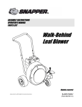
ASSEMBLY INSTRUCTIONS
OPERATOR’S MANUAL
PARTS LIST
European
Extreme Series
Walk-Behind
Leaf Blower
Series 2
Actual product may differ slightly from product pictured above
Models Covered:
ELBX10152BV
Manual No. 7043324 (I.R. - 02/28/05)
(Part # 7085927)
1
preliminaries
Congratulations!
You have just purchased one of the finest pieces of outdoor power equipment on the market today. If properly cared for,
your new blower will provide years of dependable service. Please read and follow this instruction manual carefully in order
to get the most out of your new equipment.
As you carefully unpack your unit, you will find the following items:
1 Blower Unit
1 Handle Assembly including:
1 – Upper Handle with foam grip
1 – Lower Handle
1 – Mid-Handle Support Panel
1 Front Caster Wheel Kit including:
1 – Front Caster Bracket
1 – Front Caster Wheel
1 – Axle Bolt with lock nut
1 Package of assembly hardware
1 Package containing operating manuals and warranty registration
Each product leaves our factory in excellent condition; occasionally, however, some damage may occur during shipment.
If any such damage is found upon initial inspection, immediately notify the transport carrier who delivered your machine,
as they are solely responsible for such damage, as well as any subsequent adjustments necessary.
Before assembly, please take a moment and record your model number and serial number below for future reference (both numbers are located on the silver tag attached to the machine):
Model number_______________________________
Serial number________________________________
Also be sure to promptly fill out and return the warranty registration enclosed in your manual packet.
Your new blower requires very little assembly. Simply follow the instructions contained within this manual to begin enjoying the benefits of your new unit.
CALIFORNIA PROPOSITION 65 WARNING
Gasoline and Diesel engine exhaust and some of its constituents are known to the State of California to cause cancer, birth defects and other reproductive harm.
As an owner of off-road gasoline or diesel engine equipment and/or as an employer, you also may have an obligation under the California Occupational
Safety and Health Act or under Proposition 65 to warn persons exposed to gas and diesel engine exhaust and/or other Proposition 65 chemicals in and
around your workplace. See California Health and Safety Code section 25249.5, Title 22 of the California Code of Regulations at Section 1200 er seq.,
and Title 8 of the California Code of Regulations Section 5194.
2
2
safety rules regarding outdoor power equipment
!
IMPORTANT! READ CAREFULLY THE FOLLOWING SAFETY RULES BEFORE
ASSEMBLING OR OPERATING UNIT.
• Never operate with guards not securely in place. Be sure
all safety features are attached, adjusted properly and functioning properly.
• Never operate with the discharge deflectors removed or
altered.
• Do not change the engine governor setting or over speed
the engine.
• Stop on level ground, shut off engine before leaving the
operator’s position for any reason.
• Stop equipment and inspect impeller blades after striking
objects or abnormal vibration occurs. Make necessary
repairs before resuming operations.
• Keep hands and feet away intake and discharge areas.
• Keep pets and bystanders away.
• Do not operate the unit while under the influence of alcohol or drugs.
• Use caution when crossing roads and sidewalks. Stop
engine if not blowing.
• Use care when loading or unloading the machine into a
trailer or truck.
• Use care when approaching blind corners, shrubs, trees or
other objects that may obscure vision.
TRAINING
• Read, understand, and follow all instructions in the manual and on the unit before starting. If the operator(s) or
mechanic(s) can not read English it is the owner’s responsibility to explain this material to them.
• Become familiar with the safe operation of the equipment,
operator controls, and safety signs.
• All operators and mechanics should be trained. The owner
is responsible for training the users.
• Only allow responsible adults, who are familiar with the
instructions, to operate the unit.
• Never let children or untrained people operate or service
the equipment. Local regulations may restrict the age of the
operator.
• The owner/user can prevent and is responsible for accidents or injuries occurring to themselves, other people or
property.
PREPARATION
• Evaluate the terrain to determine what accessories and
attachments are needed to properly and safely perform the
job. Use only accessories and attachments approved by the
manufacturer.
• Wear appropriate clothing including safety shoes, safety
glasses and ear protection. Long hair, loose clothing or jewelry may get tangled in moving parts.
• Inspect the area where the equipment is to be used and
remove all objects such as rocks, toys and wire, which can
be thrown by the machine.
• Use extra care when handling gasoline and other fuels.
They are flammable and vapors are explosive.
a) Use only an approved container.
b) Never remove fuel cap or add fuel with the engine running. Allow engine to cool before refueling. Do not smoke.
c) Never refuel or drain the machine indoors.
• Check that operator’s presence controls, safety switches
and shields are attached and functioning properly. Do not
operate unless they are functioning properly.
SLOPE OPERATION
Slopes are a major factor related to loss-of-control and tipover accidents, which can result in severe injury or death. All
slopes require extra caution. If you cannot back up the
slope, or if you feel uneasy on it, do not drive on it.
Do
• Blow across the face of slopes; never up and down.
• Remove obstacles such as rocks, tree limbs, etc.
• Watch for holes, ruts, or bumps. Uneven terrain could overturn the unit. Tall grass can hide obstacles.
• Keep all movement on the slopes slow and gradual. Do not
make sudden changes in speed or direction.
Do Not
• Do not start or stop on a slope. If tires lose traction, proceed slowly straight down the slope.
• Do not turn on slopes unless necessary, and then, turn
slowly and gradually downhill, if possible.
• Do not use near drop-offs, ditches, or embankments. The
operator could lose footing or balance or blower could suddenly turn over if a wheel is over the edge of a cliff or ditch,
or if an edge caves in.
• Do not operate on slopes with wet grass. Reduced footing
or traction could cause sliding.
• Do not use on excessively steep slopes.
OPERATION
• Never run an engine in an enclosed area.
• Operate only in the daylight or with good artificial light,
keeping away from holes and hidden hazards.
• Be sure of your footing while using pedestrian controlled
equipment, especially when backing up. Walk, don’t run.
• Do not operate in reverse unless absolutely necessary.
Always look down and behind before and while traveling in
reverse.
• Be aware of the blower discharge direction and do not
point it at anyone. Do not operate the blower without deflectors in place.
• Never leave a running unit unattended. Always stop engine
before leaving unit.
3
2
safety rules regarding outdoor power equipment (cont.)
• Shut off fuel while storing or transporting. Do not store fuel
near flames or drain indoors.
• Keep all hardware, especially impeller bolt, tight and keep
all parts in good working condition. Replace all worn or damaged decals.
• Never tamper with safety devices. Check their proper operation regularly.
• Clean leaves and debris from mufflers and engine to prevent fires. Clean up oil or fuel spillage.
• Stop and inspect the equipment if you strike an object.
Repair, if necessary, before restarting.
• Never make adjustments or repairs with the engine running unless specified otherwise.
• Park machine on level ground. Never allow untrained personnel to service machine.
• Carefully release pressure from components with stored
energy. (e.g. springs)
• Only replace impellers. Never straighten or weld them.
• Keep hands and feet away from moving parts.
• Frequently check components and replace with manufacturer’s recommended parts, when necessary.
• Use only factory authorized replacement parts when making repairs.
• Always comply with factory specifications on all settings
and adjustments.
• Only authorized service locations should be utilized for
major service and repair requirements.
• Never attempt to make major repairs on this unit unless
you have been properly trained. Improper service procedures can result in hazardous operation, equipment damage
and voiding of manufacturer’s warranty.
CHILDREN
Tragic accidents can occur if the operator is not alert to the
presence of children. Children are often attracted to the unit
and its activity. Never assume that children will remain
where you last saw them.
• Keep children out of the blowing area and under the watchful care of another responsible adult.
• Be alert and turn unit off if children enter the area.
• Before and during reverse operation, look behind and
down for small children.
• Never allow children to operate the unit.
• Use extra care when approaching blind corners, shrubs,
trees, or other objects that may obscure vision.
EMISSIONS
• Engine exhaust from this product contains chemicals
known, in certain quantities, to cause cancer, birth defects,
or other reproductive harm.
• Look for the relevant Emissions Durability Period and Air
Index information on the engine emissions label.
MAINTENANCE AND STORAGE
• Always observe safe refueling and fuel handling practices
when refueling the unit after transportation or storage.
• Always follow the engine manual instructions for storage
preparations before storing the unit for both short and long
term periods.
• Always follow the engine manual instructions for proper
start-up procedures when returning the unit to service.
• Never store the machine or fuel container inside where
there is an open flame, such as in a water heater. Allow unit
to cool before storing.
4
3
unit assembly
Note: Please refer to Parts List for correct part identification and placement.
FRONT WHEEL ASSEMBLY
•
•
Place Mounting Bracket against lower right corner of
Blower Housing, aligning holes in bracket with threaded
holes in housing. Secure with three 3/8-16 x 1 hex
bolts, split lock washers and flat washers. Tighten
securely.
Install Front Wheel between forks in bracket, slide
sleeve through bracket and wheel, and secure with 1/213 x 5” hex bolt and lock nut. Tighten snugly while
allowing for free rotation of wheel.
HANDLE ASSEMBLY
•
The upper handles are shipped in the folded storage
position. To unfold, loosen two handle knobs and rotate
up to the operating position. The upper handles are
secured with four knobs. Insert two 5/16-18 x 2 curved
head bolts through the handles directly below the two
shipping knobs. Place one internal tooth lock washer on
each of the bolts. Thread knobs onto curved head bolts.
Tighten all four knobs securely.
Assembly complete. Your unit is now ready to be started and checked for proper operation.
Some minor final adjustments may be required; see the Maintenance portion of this manual.
5
4
unit operation
STARTING THE ENGINE
IMPORTANT NOTE: The procedures outlined within this section are general guidelines, and are in no way meant to replace
or supercede engine manufacturer’s operating instructions. In order to obtain optimum performance from your engine, refer
to your engine manual.
!
WARNING! IMPELLER IS MOUNTED DIRECTLY TO ENGINE SHAFT – STARTING ENGINE WILL
RESULT IN IMMEDIATE HIGH-VELOCITY DISCHARGE. TO AVOID INJURY OR DAMAGE, BE
SURE DISCHARGE IS POINTED AWAY FROM PEOPLE, PETS AND PROPERTY WHEN STARTING.
BEFORE STARTING ENGINE:
•
Be sure that the unit is completely assembled, all fasteners are tightened securely, and all safety guards and components are in place.
• Be sure to check engine’s oil and fuel levels* and add as needed. (See engine manual for recommended oil and
gasoline specifications.) Never check the engine while it is running or while you are smoking. Check only when engine
is cold.
All machines are shipped without oil or fuel unless otherwise noted.
• Be sure that fuel valve is set to open position.
OPEN
CLOSED
TO START ENGINE:
•
Move choke control located on engine to the closed
“ON” position.
•
Move engine speed control, located on the handle, to
the fast “Rabbit” position.
CHOKED
ENGINE
SPEED
CONTROL
6
4
unit operation (cont.)
STARTING THE ENGINE (cont.)
•
•
Bracing unit with one hand on the upper handle and a
foot on the right rear tire, firmly grasp recoil handle and
pull briskly. You may have to pull several times before
engine starts. (If engine fails to start within a reasonable
amount of time, discontinue and check engine manual
for further instructions.) Note: Do not allow recoil rope
to snap back into recoil; damage to the rope or recoil
could result.
After engine starts, move engine speed control to
approximately half and return choke control to open
“OFF” position.
RECOIL HANDLE
PULL
BRISKLY
TO SHUT ENGINE DOWN:
•
•
•
Move engine speed control to slow “Turtle” position.
Allow engine to idle for 2-3 minutes before shutting down.
Move engine speed control to “STOP” position. Turn fuel valve to closed position.
IMPORTANT NOTE: If you experience problems with your engine that cannot be satisfactorily resolved by following the instructions contained within the engine manual, contact your local engine dealer, or call the toll-free service number listed in the repair section of the
engine manual. All engine service, warranty or otherwise, is required to be performed by a manufacturer-authorized service center. The
equipment manufacturer is neither authorized nor responsible for any type of warranty engine service, nor is it equipped to perform any
such service.
BLOWER OPERATION
!
DANGER! DO NOT PASS BY OR STAND ON THE AIR DISCHARGE SIDE OF ANY LEAF
BLOWER WITH THE ENGINE RUNNING. HIGH VELOCITY DISCHARGE CAN EASILY TURN
HARMLESS DEBRIS INTO FLYING PROJECTILES.
!
DANGER! NEVER INSERT ANY BODY PART OR FOREIGN OBJECT INTO ANY OPENING
WHILE UNIT IS RUNNING. SERIOUS INJURY OR DEATH CAN RESULT.
7
4
unit operation (cont.)
GENERAL RULES TO OBSERVE BEFORE
AND DURING OPERATION:
•
•
•
•
•
•
•
Inspect your unit before each and every use. Check for worn, bent or broken components, loose fasteners, low or flat
tires, etc., and repair or replace prior to operation. DO NOT OPERATE A MACHINE THAT IS WORN OR DAMAGED
– SERIOUS INJURY OR DEATH CAN RESULT.
Clear the entire work area of all debris that could cause damage to or become entangled in the unit. Rocks and large
branches can wedge themselves between the impeller and housing, causing equipment damage or personal injury. If
in doubt, remove it.
Do not start unit until you are ready to begin blowing, and promptly shut off unit as soon as operation is complete.
Keep hands, feet and clothing away from rotating parts. Never place your feet or hands in path of discharge.
Use proper discretion in selecting your debris removal pattern, especially on uneven terrain. Avoid steep hills, especially if surface is wet. Do not travel straight down slopes exceeding 14 degrees. If tires begin to slip when climbing a
slope, the grade is too steep for safe operation. Angle the unit to a less steep slope until tires stop slipping and traction is regained.
Be keenly aware of your surroundings while operating unit – children and pets can pop out of nowhere.
Learn to listen to your machine – being aware of what a well-running unit sounds like can alert you to a potential problem. A straining engine or clanging impeller means that trouble is almost sure to follow.
TO CHANGE AIR DISCHARGE DIRECTION:
•
•
To direct air discharge out from the front of the machine,
open the forward air deflector door, mounted on the
front of the discharge end of the blower, by pushing the
control lever to the front of the machine. This feature is
ideal for such things as blowing debris from a wall or
fence. Adjust engine speed to increase or decrease air
discharge rate.
To direct air discharge out from the side of the machine,
close the forward air deflector door by pulling the control
lever toward the back of the machine. Adjust the discharge deflector up or down to control angle of discharge. This feature is ideal for such things as blowing
debris into neat rows. Adjust engine speed to increase
or decrease air discharge rate. IMPORTANT: SHUT
UNIT DOWN BEFORE ADJUSTING SIDE DEFLECTOR.
FRONT
SIDE
ADJUST
HINTS FOR EFFECTIVE OPERATION:
•
•
For operator ease and maneuverability, push down on the upper handle while walking so that the machine balances
on the rear wheels.
When blowing dry debris, set blower discharge to lower rate; when blowing wet or frozen debris, increase discharge
rate.
8
5
!
maintenance
BEFORE MAKING ANY ADJUSTMENTS, STOP ENGINE AND DISCONNECT SPARK PLUG
WIRE TO PREVENT INADVERTENT STARTING OF UNIT.
GENERAL:
•
•
•
•
•
•
•
•
Follow implicitly the engine manufacturer’s recommendations for maintenance.
Always keep your machine clean – especially the engine. Check all adjustments periodically. Also, periodically check
that all fasteners are secure.
Never make any adjustments to the unit until the engine is off and the spark plug wire is disconnected.
If carburetor adjustment is necessary, stand to one side and keep feet and hands in the clear while making adjustments.
Keep engine free of accumulations of grass, leaves or excessive grease. An accumulation of these combustible materials may result in a fire.
Store gasoline in a safe and approved container in a cool, dry place.
Keep the unit and any fuel containers in locked storage to prevent children from playing and/or tampering with them.
Do not store gasoline powered equipment or fuel containers in a basement or any closed area where heating or heat
appliances or open pilot lights are present, unless the fuel is completely drained from the power equipment and the fuel
containers.
LUBRICATION:
•
The tires on your blower contain bearings that should be lubricated on a weekly basis using a high-performance, automotive quality grease to ensure long life and minimal wear.
9
5
!
maintenance (cont.)
BEFORE MAKING ANY ADJUSTMENTS, STOP ENGINE AND DISCONNECT SPARK PLUG
WIRE TO PREVENT INADVERTENT STARTING OF UNIT.
TROUBLESHOOTING:
•
•
•
UNIT WILL NOT START:
• Check fuel and oil levels.
• Check to make sure choke is set when engine is cold, off when hot.
• Check throttle for proper operation.
• Check intake baffle for jammed debris or accumulation of debris.
• If condition persists, contact dealer.
UNIT STALLS:
• Check fuel and oil levels.
• Check intake baffle for jammed debris or accumulation of debris.
• If condition persists, contact dealer.
EXCESSIVE NOISE OR VIBRATION:
• Check to make sure all fasteners are tightened securely.
• Remove intake baffle and visually inspect impeller for broken, bent, or cracked blades; also make sure impeller hub
is securely tightened onto engine shaft – bolt should be torqued to 15 ft/lbs. Pull recoil and check for bent engine
shaft. Contact dealer for repair or replacement if necessary. Do not attempt to repair a damaged impeller or
bent engine shaft. Serious injury or equipment damage may result.
!
•
BEFORE REMOVING INTAKE BAFFLE, OR ANY OTHER COMPONENT, STOP ENGINE AND DISCONNECT
SPARK PLUG WIRE TO PREVENT INADVERTENT STARTING OF UNIT.
UNIT DOES NOT TRAVEL STRAIGHT:
• Check camber on front wheel, adjust as needed. See Front Wheel Camber Adjustment.
• Make sure wheels are lubricated – see Lubrication.
10
5
maintenance (cont.)
ADJUSTMENTS:
!
•
BEFORE MAKING ANY ADJUSTMENTS, STOP ENGINE AND DISCONNECT SPARK PLUG
WIRE TO PREVENT INADVERTENT STARTING OF UNIT.
THROTTLE CABLE ADJUSTMENT: Correct cable
adjustment allows for full range of movement of throttle
body on engine in conjunction with throttle control on
handle. To adjust, loosen cable clip screw on engine,
then slide cable housing in or out in approximately 1/81/4” increments. Retighten screw, recheck, and readjust as needed.
LOOSEN SCREW
MOVE CABLE
•
FRONT WHEEL CAMBER ADJUSTMENT: Correct
camber adjustment will place the front axle at 0
degrees, or parallel with level ground, and the wheel at
90 degrees or perpendicular with level ground. Adjust
by loosening the three mounting bolts and placing a
square aside the wheel and adjusting until square sits
flat on ground and touches upper and lower points of
tire, then retightening bolts. An alternate method is to
place a level against the side of the caster bracket.
0O
90O
REPLACEMENT PARTS:
•
Replacement parts are available through your dealer.
11
6
illustrated parts list
12
6
illustrated parts list (cont.)
Item
Part No.
Qty
Description
1
2
3
-----4
5
6
7
8
9
10
11
11A
11B
12
-13
14
15
16
17
18
19
20
21
22
23
24
25
-26
27
28
29
30
31
32
33
34
35
36
37
38
39
40
41
42
7043267
75892
3039111
3071815
3071814
91581
7078095
7078096
91540
91601
7078069
90238
91527
12315
3071776
3021599
3021595
3021597
3020233
3079269
91523
7078106
91318
46465
7078149
7078150
91530
91584
3071782
3031103
22151
90372
3033001
3033107
91628
12763
7078139
91304
91320
90517
58167
91822
91894
33753
3032160
91315
1717312
33866
3023276
74422
91189
1
1
1
1
1
4
1
6
4
4
1
4
3
1
4
1
1
1
1
1
2
1
10
1
1
1
2
2
1
1
1
1
2
4
2
2
1
3
3
3
1
1
1
1
4
17
4
1
1
1
4
WELDMENT, Housing- Extreme Blower, LBX10152BV
DECAL - Danger-Flying Material - See DECAL IDENTIFICATION
ENGINE, B&S 10HP Intek OHV
SCREW, Clamp Casing, Briggs Intek Engine (Not Shown)
CLAMP, Casing, Briggs Intek Engine (Not Shown)
SCREW, 8-18 x 1-1/2” Self Thread (Not Shown)
GUARD, Wire Muffler, 10HP Intek Engine (Not Shown)
SCREW, Muffler Guard (Not Shown)
SCREW, 5/16-18 x 1-1/2 Hex Head Cap, GR5
NUT, 5/16-18 Hex Flange Lock, GR5
DECAL - Sound Rating - See DECAL IDENTIFICATION
SCREW, 5/16-24 x 1" Hex Head Cap
SCREW, 5/16-18 x 1-1/4", Hex Head Cap, GR5
KEY, 1/4" Square x 1-7/16"
KNOB, Fluted- Folding Handles
ASSEMBLY, 15" 9 Blade Impeller (Includes items 11A, 11B & 3 ea items 8 & 37)
IMPELLER, Cast, 15" O.D.
HUB, Taper-Lok, Type 1 - P1 x 1.125 (1.938 OAL)
WELDMENT, Intake Baffle- Extreme
DECAL - ‘Easy-Off Impeller’ - See DECAL IDENTIFICATION
SCREW, 5/16-18 x 5/8” Hex Washer Self-Tap
DEFLECTOR, Side Air
SCREW, 5/16-18 x 3/4" Hex Head Cap
GUIDE, Rope (1/4-20 thread)
ROD, Door Front/Side Discharge
DOOR, Forward Air Control
BOLT, 1/4-20 x 3/4” Carriage
NUT, 1/4-20 Hex Flange
SPRING, Extension- Side Air Discharge Door
KNOB, Ball Hand Lever- 3/8-16 Metal Insert
SLEEVE, Front Axle
NUT, 1/4-20 Hex Center Lock, GR5 or B
ASSY., Wheel & Tire 410/350-4
BALL BEARING, 5/8 x 1-3/8" (include with wheel assembly, item 25)
WASHER, .64 x .99 x .05 Flat
RING, External Retaining (TRU1500-62)
BRACKET, Front Wheel Mounting, Extreme/WJ
SCREW, 3/8-16 x 1” Hex Head Cap
WASHER, 3/8" Split Lock
WASHER, 3/8" Flat
ASSY., Tire & Wheel 9 x 350-4
BOLT, 1/2-13 x 5" Hex Head Cap
NUT, 1/2-13 Hex Center Lock, GR5
HANDLE, Lower Folding- Wide- Blower
MOUNT, Vibration
WASHER, 5/16" Split Lock
WASHER, 5/16" Curved
DASH PANEL, Blower- Wide
ASSY, Upper Handle & Grip- Wide (p/n 33696 + grip)
GRIP, 1.0 x 21-1/2" Foam
BOLT, 5/16-18 x 2", Curved Head Square Neck, GR2
13
6
illustrated parts list (cont.)
Item
Part No.
Qty
Description
43
44
45
46
47
48
49
50
51
52
53
54
54
55
---
90391
3071800
7078169
90505
90188
76978
91298
91601
75893
29776
7078087
27255
1722551
73462
22841
7011279
4
1
2
1
14
1
4
4
1
1
1
1
1
1
1
1
WASHER, 5/16" Internal Tooth Lock
THROTTLE CONTROL, Briggs
BEARING, 3/8” Clip
SCREW, 1/4-20 x 2" Hex Head Cap, GR5
WASHER, .34 x .69 x .08 Flat
NUT,1/4-20 Hex Nyloc
NUT, 5/16-18 Hex Nyloc
NUT, 5/16-18 Hex Flange Lock, GR5
DECAL - Personal Protection - See DECAL IDENTIFICATION
DECAL - Euro Certification - See DECAL IDENTIFICATION
DECAL - Extreme Logo - See DECAL IDENTIFICATION
DECAL - Snapper Logo - See DECAL IDENTIFICATION
DECAL - Simplicity Logo - See DECAL IDENTIFICATION
DECAL - Warning Combo - See DECAL IDENTIFICATION
DECAL - Cut Finger - See DECAL IDENTIFICATION
DECAL - Model Year 2005 - See DECAL IDENTIFICATION
14
7
decal identification
75893 - EAR/EYE/BREATHING PROTECTION
REQUIRED - LOCATED ON SIDE OF BLOWER
HOUSING
29776 - EUROPEAN CERTIFICATION LOCATED ON REAR OF BLOWER HOUSING
75892 - DANGER-FLYING MATERIAL LOCATED ON SIDE OF BLOWER HOUSING
22841 - WARNING-CUT FINGER - LOCATED
ABOVE BLOWER DISCHARGE
7011279 - MODEL YEAR 2005 - LOCATED
ON REAR OF BLOWER HOUSING
7078069 - NOISE RATING - LOCATED
ON REAR OF BLOWER HOUSING
15
7
decal identification (cont.)
73462 - WARNING COMBO - LOCATED
ON TOP OF BLOWER HOUSING
27255 - SNAPPER LOGO - LOCATED ON MIDHANDLE PANEL (ON APPLICABLE MODELS)
1722551 - SIMPLICITY LOGO - LOCATED ON
MID-HANDLE PANEL (ON APPLICABLE MODELS)
3079269 - ‘EASY-OFF IMPELLER’ LOCATED ON INTAKE BAFFLE
EUROPEAN PERFORMANCE:
Maximum level of vibration measured
at the operator’s hand 16 m/sec2
7078087 - EXTREME LOGO LOCATED ON INTAKE BAFFLE
16
notes
17
notes
18
notes
19
ASSEMBLY INSTRUCTIONS
OPERATOR’S MANUAL
PARTS LIST
European
Extreme Series
Walk-Behind
Leaf Blower
Series 2
McDonough, GA 30253 USA
Manual No. 7043324 (I.R. - 02/28/05)
20