1
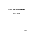
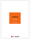
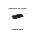
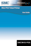
ABOUT THE EZ SWITCH 10/100 SAMPLE APPLICATIONS SMC-EZ108DT The EZ Switch 10/100 (SMC-EZ108DT) is an 8-port Fast Ethernet switch. Its 8 10BASE-T/100BASE-TX ports deliver dedicated 10/100 Mbps links to each attached LAN segmentall with conventional cabling and adapters. AutoNegotiation is used to select the optimal transmission speed and communication mode for each connection. With storeand-forward switching and flow control, maximum data integrity is always maintained, even under heavy loading. Easy installation and reliability make this plug-and-play switch an ideal choice for smooth Fast Ethernet integration. Features and Benefits ◆ Auto-Negotiation of half or full-duplex on all ports ◆ ANSI/IEEE 802.3u compliance ensures compatibility with standards-based hubs, switches and cards from any vendor ◆ Store-and-forward switching ensures error-free transmission ◆ Half- and full-duplex flow control prevents packets from being dropped under heavy loading ◆ Plug and play ◆ Built-in wiring crossovers on all ports allow connections to servers and workstations to be made with straight-through cabling ◆ At-a-glance LEDs for port and system status monitoring ◆ Desktop and rack mountable Front-Panel LEDs The front panel of the switch provides a link status LED for each RJ-45 port. In addition, the front panel also contains status LEDs for at-a-glance system monitoring. The following table details the functions of the various indicators: LEDs Some typical applications for the EZ Switch 10/100 are illustrated below: Rear Panel INSTALLING FDX Front-Panel Ports The front-panel ports are dual-speed RJ-45 ports with built-in wiring crossovers. PCs can be connected to these ports with straight-through cable. Each port supports Auto-Negotiation, so the optimum communication mode (half or full duplex) and data rate (10 Mbps or 100 Mbps) are selected automatically. Port 8 on the switch doubles as a crossover port and a straight-through daisy-chain port. The daisy-chain port makes it convenient to connect straight-through cable from the EZ Switch 10/100 to a crossover port on another device. THE SWITCH The EZ Switch 10/100 can be placed on a desktop or shelf, or installed in a standard 19-inch equipment rack. Equipment Checklist After unpacking the EZ Switch 10/100, check the contents of the box to be sure youve received the following components: EZ Switch 10/100 SMC-EZ108DT Appropriate AC power cable Four adhesive foot pads SMC Warranty Registration Card This User Guide Selecting a Site Be sure to follow the site selection guidelines below when choosing a location: u Po w e r Gre e n Lin k /Ac t Gre e n 100M Make sure twisted-pair cable is always routed away from power lines, fluorescent lighting fixtures and other sources of electrical interference such as radios, transmitters, etc. u Make sure that a properly grounded power outlet is within 8 feet (2.44 meters) of the switch and is powered from an independent circuit breaker. As with any equipment, using a filter or surge suppressor is recommended. The AC power receptacle is located on the rear panel of the switch. Port and Switch Status LEDs Co n d i ti o n St a t u s Sw itc h is re c e ivin g p o w e r. In d ic a te s th a t th e c o n n e c tio n b e tw e e n p o rt a n d a tta c h e d d e vic e is va lid . Fla s h in g Gre e n In d ic a te s th a t th e s w itc h is tra n s m ittin g o r re c e ivin g d a ta . Gre e n In d ic a te s th a t th e p o rt is o p e ra tin g a t 100 Mb p s . Gre e n In d ic a te s th a t th e p o rt is o p e ra tin g in fu ll-d u p le x m o d e . Fla s h in g Gre e n In d ic a te s a c o llis io n o c c u re d o n th e p o rt s e g m e n t w h e n o p e ra tin g in h a lfd u p le x m o d e . u u Select a suitable location for the switch: It should be accessible for installing, cabling and maintaining the switch. The temperature and humidity should be within the ranges listed in the specifications. The status LEDs should be clearly visible. There should be adequate space (approximately two inches) on all sides for proper air flow. Before rack mounting the switch, pay particular attention to the following factors: Temperature: Since the temperature within a rack assembly may be higher than the ambient room temperature, check that the rackenvironment temperature is within the specified operating temperature range. Mechanical Loading: Do not place any equipment on top of a rack-mounted switch. Circuit Overloading: Be sure that the supply circuit to the rack assembly is not overloaded. Grounding: Rack-mounted equipment should be properly grounded. Particular attention should be given to supply connections other than direct connections to the mains. Standalone LAN Instructions 1. Positioning the Switch: For desktop or shelf mounting, attach the four adhesive foot pads to the bottom of the switch. For rack-mounting, attach the mounting brackets to both sides of the switch with the screws provided, then install the switch in the rack. 2. Applying Power: Plug one end of the power cable into the power receptacle at the back of the switch, and the other end into an appropriate electrical outlet. Check the Power LED to be sure it is on. Note: It is not necessary to power off the switch before connecting or disconnecting any UTP cables, as these actions will not disrupt the operation of other devices attached to the switch. 3. Connecting PCs: Connect each PC to an RJ-45 port on the switch with a straight-through twisted-pair cable segment, maximum length 100 meters (328 feet). The EZ Switch 10/100 will support up to 8 PCs. However, if using port 8 be sure to use the fixed crossover port marked X on the switch. Note: If an attached device does not support AutoNegotiation, the data rate will be sensed automatically and the communication mode will default to half duplex. 4. Cascading Switches and Other Network Devices: If you need more ports, connect the daisy-chain port, marked = on port 8, to a crossover port on another device. Be sure to use straight-through twisted-pair cable, maximum length 100 meters (328 feet). Note that if you are using the daisy-chain port you cannot use the fixed crossover port, marked X on port 8. Note: Alternatively, you can cascade from any crossover port on the switch to a daisy-chain port on another device. You may also connect to crossover ports at both ends if you use a crossover cable. See the Cable Specifications and Connectivity Guidelines sections of this guide for further information. High-Speed Switch Links TROUBLESHOOTING 1. Symptom Power LED does not light after power on. Probable Causes Power outlet or power cord may be defective. Possible Solutions Check for loose connections. Check the power outlet by using it for another device. Replace the power cord. 2 . Symptom Link LED does not light after connection is made. Probable Causes Switch port, network card or cable may be defective. Possible Solutions Check that the switch and attached device are both powered on. Be sure the network cable is connected to both devices. Verify that Category 5 cable is used for 100 Mps connections and that the length of any cable does not exceed 100 meters (328 feet). Check the network card and cable connections for defects. Replace the defective card or cable if necessary. COPYRIGHT EZ SWITCH 10/100 SPECIFICATIONS SMC-EZ108DT User Guide Information furnished by SMC Networks, Inc. (SMC) is believed to be accurate and reliable. However, no responsibility is assumed by SMC for its use, nor for any infringements of patents or other rights of third parties which may result from its use. No license is granted by implication or otherwise under any patent or patent rights of SMC. SMC reserves the right to change specifications at any time without notice. Copyright © 2000 by SMC Networks, Inc. 6 Hughes, Irvine, California. All rights reserved. Printed in Taiwan TRADEMARKS SMC is a registered trademark; and EZ Switch is a trademark of SMC Networks, Inc. Other product and company names are trademarks or registered trademarks of their respective holders. LIMITED LIFETIME WARRANTY Complete warranty information for all SMC products is available on SMCs web site at http://www.smc.com. ◆ Full-duplex support on all ports ◆ Half- and full-duplex flow control ◆ Desktop and rack mountable ◆ Plug and play—no software, no switches, nothing to load ◆ Auto-Negotiation of speed and duplex mode 8-Port Fast Ethernet Switch EZ Switch 10/100 FOR LITERATURE OR ADVERTISING RESPONSE, CALL: U.S.A. and Canada: (800) SMC-4-YOU; Fax (949) 707-2460 Spain: 34-93-477-4920; Fax 34-93-477-3774 UK: 44 (0) 1189 748700; Fax 44 (0) 1189 748701 Southern Europe: 33 (1) 41.18.68.68; Fax 33 (1) 41.18.68.69 Central/Eastern Europe: 49 (0) 89 92861-200; Fax 49 (0) 89 92861-230 Nordic: 46 (8) 564 33145; Fax 46 (8) 87 62 62 Middle East: 971-48818410; Fax 971-48817993 South Africa: 27 (0) 11-3936491; Fax 27 (0) 11-3936491 PRC: 86-10-6235-4958; Fax 86-10-6235-4962 Taiwan: 886-2-2747-4780; Fax 886-2-2747-9220 Asia Pacific: (65) 238 6556; Fax (65) 238 6466 Korea: 82-2-553-0860; Fax 82-2-553-7202 Japan: 81-45-224-2332; Fax 81-45-224-2331 Australia: 61-2-9416-0437; Fax 61-2-9416-0474 India: 91-22-8204437; Fax 91-22-8204443 Publication Number: 150985-101 E082000-R03 LEDs Power - one Link/Act (activity) - one per port 100M (100 Mbps) - one per port FDX (full duplex) - one per port FCC Class B MAC Address Table 1K entries This equipment has been tested and found to comply with the limits for a Class B digital device, pursuant to Part 15 of the FCC Rules. These limits are designed to provide reasonable protection against harmful interference in a residential installation. This equipment generates, uses and can radiate radio frequency energy and, if not installed and used in accordance with instructions, may cause harmful interference to radio communications. However, there is no guarantee that the interference will not occur in a particular installation. If this equipment does cause harmful interference to radio or television reception, which can be determined by turning the equipment off and on, the user is encouraged to try to correct the interference by one or more of the following measures: European contact: SMC Networks Europe Edificio Conata II Calle Fructuós Gelabert 6-8, 2º, 4ª 08970 - Sant Joan Despí Barcelona, Spain This information technology product complies with ISO/IEC Guide 22 and EN45014. It conforms to the following specifications: EN55022(1988)/CISPR-22(1985) Class B EN50082-1: IEC 1000-4-2, 3, 4 This information technology product complies with the requirements of the Low Voltage Directive 73/23/EEC and the EMC Directive 89/ 336/EEC and carries the CE Mark accordingly. Industry Canada - Class B This digital apparatus does not exceed the Class B limits for radio noise emissions from digital apparatus as set out in the interferencecausing equipment standard entitled Digital Apparatus, ICES-003 of Industry Canada. Cet appareil numérique respecte les limites de bruits radioélectriques applicables aux appareils numériques de Classe B prescrites dans la norme sur le matérial brouilleur: Appareils Numériques, NMB-003 édictée par lIndustrie. VCCI Class B Australia AS/NZS 3548 (1995) - Class B Safety Compliance 6 Hughes, Irvine, CA 92618 Phone: (949) 707-2400 Network Interface RJ-45: 100 ohm, UTP cable 10BASE-T - EIA/TIA Categories 3, 4, or 5 100BASE-TX - EIA/TIA Category 5 Switching Method Store-and-forward EC Conformance Declaration - Class B INTERNET E-mail addresses: [email protected] [email protected] Driver updates: http://www.smc.com/support.html World Wide Web: http://www.smc.com/ FTP Site: ftp.smc.com Ports 8 RJ-45 ports Ports 1-7: Twisted-pair, fixed crossover Port 8: Twisted-pair, choice between fixed crossover or straight-through (daisy-chain port) COMPLIANCES Reorient the receiving antenna Increase the separation between the equipment and receiver Connect the equipment into an outlet on a circuit different from that to which the receiver is connected Consult the dealer or an experienced radio/TV technician for help FOR TECHNICAL SUPPORT, CALL: From U.S.A. and Canada (8:30 AM - 8:00 PM Pacific Time) (800) SMC-4-YOU; (949) 707-2400; (949) 707-2460 (Fax) From Europe (8:00 AM - 5:30 PM UK Greenwich Mean Time) 44 (0) 1189 748740; 44 (0) 1189 748741 (Fax) Model SMC-EZ108DT Australian Contact: SMC Australia Suite 18, 12 Tryon Road, Lindfield, NSW 2070 Phone: 61-2-9416-0437 Fax: 61-2-9416-0474 CSA/NRTL (C22.2.950, UL 1950) EN60950, (IEC 950) Memory Buffer 1 Mbyte per unit CABLE SPECIFICATIONS Cable Type and Connector 10BASE-T Cable Ty p e Le n gth Ca te g o ry 3, 4, 5 UTP 100 m ( 328 ft) Co n n e cto r RJ-45 100BASE-TX Cable Ty p e Ca te g o ry 5 UTP Le n gth 100 m ( 328 ft) Co n n e cto r RJ-45 RJ-45 Connector Pin Assignments Caution: DO-NOT plug a phone jack connector into any RJ-45 port. Use only twisted-pair cables with RJ-45 connectors that conform with FCC standards. An Ethernet or Fast Ethernet twisted-pair link segment requires two pairs of wires. Each wire pair is identified by two different colors. For example, one wire might be green and the other, green with a white stripe. Each wire pair must be attached to in a specific orientation. Note how numbered in the illustration below. connectors in the same orientation wires to the pins. the RJ-45 connector the pins are Be sure to hold the when attaching the Filtering/Forwarding/Learning Rates Full line rate Size 9.88 x 4.65 x 1.46 in (25.1 x 11.8 x 3.7 cm) Weight 1.76 lbs (0.8 kg) Temperature Operating: 32° to 122°F (0° to 50°C) Storage: -25° to 158°F (-13° to 70°C) Humidity, non-condensing 5% to 95% Power Requirements Universal AC input; 100 to 240 VAC, 50 to 60 Hz Power Consumption 10 Watts maximum Heat Dissipation 68 BTU/hr maximum RJ-45 Pin Assignments Straight-Through Cable En d 1 1 ( Tx +) 2 ( Tx -) 3 ( Rx +) 6 ( Rx -) En d 2 1 ( Tx +) 2 ( Tx -) 3 ( Rx +) 6 ( Rx -) RJ-45 Pin Assignments Crossover Cable En d 1 1 ( Tx +) 2 ( Tx -) 3 ( Rx +) 6 ( Rx -) En d 2 3 ( Rx +) 6 ( Rx -) 1 ( Tx +) 2 ( Tx -) Note: The + and - signs are used to represent the polarity of the wires that make up each wire pair. CONNECTIVITY GUIDELINES Crossover/Straight-Through Wiring Requirements If t h e por t on t h e EZ Sw it ch 1 0/1 00 is... A n d t h e por t on t h e ot h er dev ice is... Th en u se...cabl e C r ossover (x ) C r ossover C r ossover C r ossover (x ) St r ai gh t -t h r ou gh St r ai gh t -t h r ou gh Standards ANSI/IEEE 802.3 ANSI/IEEE 802.3u ANSI/IEEE 802.3x St r ai gh t -t h r ou gh (= ) C r ossover St r ai gh t -t h r ou gh St r ai gh t -t h r ou gh (= ) St r ai gh t -t h r ou gh C r ossover EMC/Safety Compliances CE Mark Emissions FCC Class B VCCI Class B EN55022 (CISPR 22) Class B C-Tick - AS/NZS 3548 (1995) Class B Immunity IEC 1000-4-2/3/4 Safety CSA/NRTL (C22.2.950, UL 1950) TÜV/GS (EN60950) Re p e a te r Ty p e Tw i s te d Pa i r a n d Nu m b e r 1 0 0 BASE-TX 1 Cla s s I 200 m ( 656 ft) 1 Cla s s II 200 m ( 656 ft) 2 Cla s s II 205 m ( 672. 4 ft) Maximum Current 0.2A @ 110 VAC 0.1A @ 240 VAC Limited Warranty Lifetime Maximum Fast Ethernet Network Diameter Tw i s te d Pa i r /Fi b e r 1 0 0 BASE-TX a n d FX 260. 8 m ( 855. 4 ft) 308. 8 m ( 1012. 6 ft) 216. 2 m ( 709. 1 ft) Note: Network diameter is defined as the wire distance between two end stations in the same collision domain.