1
Motion Alert
Model HA-318
1. INTRODUCTION
The Motion Alert is designed to monitor movement around your
house. The motion sensor can be placed either indoor or outdoor.
Once motion is detected, the receiver will beep & flash.
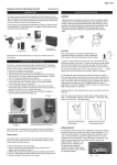
In this package, you should find an Indoor/Outdoor Motion Sensor, a
Houselink® Receiver, an adapter, ball-head joint, screws and a clip.
2. SET UP THE INDOOR/OUTDOOR MOTION SENSOR AND HOUSELINK® RECEIVER
1. CODE CONNECTORS
2. ZONE CONNECTORS
In order for the sensor to communicate with the receiver properly,
the sensor’s code must match with the receiver’s code. Code
connectors 1 to 6 can be found by opening the battery cover and
back cover of the receiver. User is required to set these code
connectors randomly and the code settings on both sensor and
receiver must be the same. Each position of the code connector
can be set to “+”, “-‘ or “0” positions. Refer to the diagram below
to set the code connectors properly.
Each receiver can work with up to 4 different sensors (to represent 4
different zones on the receiver). There are 2 connectors that determine
the zone number 1, 2, 3 and 4. These 2 connectors can be found by
opening the battery cover. Please follow table 1 to set the zone.
Note: A connector can be
removed with the clip,
as shown.
‘0’
Ball-head joint
Indoor/Outdoor
Motion Sensor
‘+’
Adapter
2 pcs 3 x 18 screws
(Included)
Clip
Clip
Houselink®
Receiver
Please follow the instructions below to setup your motion sensor
and the receiver.
Code Connectors on Motion Sensor
A
B
Zone 1
+
+
Zone 2
+
-
Zone 3
-
+
-
-
Zone 4
‘-’
Zone connectors
Table 1
Code Connectors on Receiver
Note: If you experience interference from a nearby system, which could accidentally trigger your
system, please change the code settings on the sensor and receiver. The code setting on the
sensor and receiver should still match after changing the code setting.
“+” in the table means the connector for that position should be placed on
the posts.
“-“ in the table means the connector for that position should be removed.
3. POWER UP THE INDOOR/OUTDOOR MOTION SENSOR AND RECEIVER
1. POWER UP
2. SENSOR SENSITIVITY
3. MOUNTING
After setting up all the connectors properly, both units are now ready to be powered up.
The sensitivity of the motion sensor is adjustable. Change the
setting by placing the connector on either the ”High” or “Low”
position. When the sensitivity is set to “Low”, more movement
is required to trigger the sensor. It is recommended to set the
sensitivity to “Low” and perform a “Walk Test” (Described in
Section 3 - “Walk Test”). If the walk test result is satisfied, the
sensitivity does not require to be adjusted further. If the walk
test result shows the sensitivity is too low, then you can change
the sensitivity setting to
“High”. Please perform the
walk test after changing the sensitivity setting.
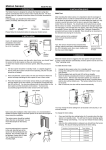
A ball-head joint is necessary to mount the sensor at a desire location.
A height of 5-6 ft is recommended, depending on your application. Once
a location is selected, mount the ball-head joint to this location by screws
provided, (see diagram 1). Once the ball-head joint is mounted to the
wall, slide the back of the sensor into the ball-head joint (see diagram 2).
The mounting angle can be adjusted. Please refer to Section 3 “Walk
Test” to determine the best mounting angle.
Insert a 9V alkaline battery (not included) to the motion sensor and its LED will be on for 2 seconds. The
receiver will beep and red LED flash. The sensor requires a warm up time of approx. 45 seconds before
it can function properly. After powering up the sensor, face it to the wall where no motion will be
detected. After 45 seconds, the sensor is ready. Wave your hand in front of the sensor, the receiver will
beep and red LED will flash for
approx. 15 seconds.
Plug in the adapter to the receiver,
the green LED will start flashing
indicating the receiver unit is
powered up but no sensor is
detected.
Plug in the adapter to the receiver
Insert 9V alkaline battery to the sensor
Sensitivity Connectors
on Motion Sensor
Diagram 1
Diagram 2
4. OPERATION
3. POWER UP THE INDOOR/OUTDOOR MOTION SENSOR AND RECEIVER (CONT)
4. WALK TEST
After mounting the sensor at the desired location, it is important to perform a
walk test in order to determine if the sensor is detecting the things you want
to detect.
When motion is detected in the monitored area, the sensor will
send a signal to the receiver. It will beep and the corresponding
zone red LED will flash for 15 seconds.
If the sensor is set to zone 1, zone 1 red LED on the receiver
will flash, and the receiver will emit a continuous “single beep”,
i.e. “beep” pause, “beep”, pause….. etc.
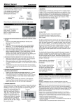
In order to control how far the sensor can “see”, this can be done by
adjusting the angle of the sensor. To reduce the detection range, simply
move the sensor downward. To increase the range, move the sensor up to
around 12 degrees. This will give the maximum range. However, this may
not be desired if the sensor is placed outdoors, since a false trigger may
occur if the sensor is set to detect motion in a distance.
If the sensor is set to zone 4, zone 4 red LED will flash, and the
receiver will emit a continuous “4 beeps”, i.e. “beep beep beep
beep” pause “beep beep beep beep” pause ……etc.
5. BUZZER VOLUME
You can select the buzzer volume by
switching the volume switch to “HI” or
“LO” position.
Perform walk test in the undesired area to ensure movement cannot be
detected.
8. OTHER HOUSEHOLD ALERT
®
TM
SENSORS
The Houselink receiver can work with up to 4 different sensors:
garage door monitor sensors, door / window sensors, water
sensors, indoor/outdoor motion sensors, etc. Please visit
www.skylinkhome.com or contact us at [email protected]
for more information of how to fully utilize your Motion Alert.
When a sensor is triggered for a long period of time, you may stop the
buzzer by pressing the mute button. When another signal comes again,
you can disable the buzzer for all currently activated sensors by pressing
the mute button. The receive will beep again if it receives another signal.
For instance, if you are working on your
lawn with the garage door open, you may
want to disable the buzzer for this garage
door only. Then you can press the “Mute”
button after it starts to sound. If any other
sensor is triggered, the receiver will sound
again.
By the number of beeps emitted by the receiver, user can
identify which zone is triggered.
You should walk in the area that you would like the sensor to monitor. The
receiver will beep if the sensor detects your movement. If the receiver does
not respond, adjust the mounting angle accordingly. Perform the walk test
again after 30 seconds. Repeat this procedure until your motion is detected.
There should be no movement in the detected area during the 30 seconds.
Tips: The sensor should not face towards direct sunlight, placing near heat or
cold producing devices (i.e. A/C or furnance vents, fans, ovens, heaters etc.)
that may cause false triggers.
6. MUTE
12º
The buzzer can be disabled by switching
to the “OFF” position.
7. LOSS OF SIGNAL INDICATION
When the battery level on the sensor drops to a certain level, or the
sensor is out of the operating range, the receiver will show a “loss of
signal” indication. The red LED representing that zone will flash rapidly,
i.e. if zone 1 sensor is lost, the zone 1 red LED will flash rapidly.
When the loss of signal indication occurs, move the receiver closer to the
corresponding sensor and trigger that sensor. If the red LED stops flashing rapidly, that means the receiver or sensor needs to be relocated. If the
“loss of signal” indication persists, replace the battery of that sensor.
9. FCC
This device complies with Part 15 of the FCC Rules. Operation is subject to the following two conditions: (1) This device
may not cause harmful interference, and (2) This device must accept any interference received, including interference that
may cause undesired operation.
WARNING:
Changes or modifications to this unit not expressly approved by the party responsible for compliance could void the user’s
authority to operate the equipment.
NOTE:
This equipment has been tested and found to comply with the limits for a Class B digital device, pursuant to Part 15 of the
FCC Rules. These limits are designed to provide reasonable protection against harmful interference in a residential
installation. This equipment generates, uses and can radiate radio frequency energy and, if not installed and used in
accordance with the instructions, may cause harmful interference to radio communications.
However, there is no guarantee that interference will not occur in a particular installation. If this equipment dose cause
harmful interference to radio or television reception, which can be determined by turning the equipment off and on, the user is
encouraged to try to correct the interference by one or more of the following measures:
- Reorient or relocate the receiving antenna.
- Increase the separation between the equipment and receiver.
- Connect the equipment into an outlet on a circuit different from that to which the receiver is connected.
- Consult the dealer or an experienced radio/TV technician for help.
10. WARRANTY
If, within one year from date of purchase, this product should become defective
(except battery), due to faulty workmanship or materials, it will be repaired or
replaced, without charge. Proof of purchase and a Return Authorization are required.
11. CUSTOMER SERVICE
If you would like to order Skylink’s products or have difficulty getting them to
work, please :
1. visit our FAQ website at www.skylinkhome.com, or
2. email us at [email protected] (reply within 24 hrs), or
3. call our toll free at 1-800-304-1187 from Monday to Friday, 9 am to 5 pm EST.
Fax +800 286-1320
CUSTOMER
SERVICE
Email:[email protected] (Reply within 24 hrs)
http://www.skylinkhome.com
P/N. 101A205-002 Rev.2
©2003 SKYLINK GROUP